
Related Manuals for SEW-Eurodrive ECDriveS Series


Summary of Contents for SEW-Eurodrive ECDriveS Series
- Page 1 *28507088_1118* Drive Technology \ Drive Automation \ System Integration \ Services Operating instructions ® ECDriveS ECC-DBC Binary Control, ECR Roller Drive , ECG Gearmotor Edition 11/2018 28507088/EN...
- Page 2 SEW-EURODRIVE—Driving the world...
-
Page 3: Table Of Contents
Table of contents Table of contents General information........................ 5 About this documentation .................... 5 Information on this documentation.................. 5 Structure of the safety notes ................... 5 1.3.1 Meaning of signal words ................ 5 1.3.2 Structure of section-related safety notes............ 5 1.3.3 Structure of embedded safety notes .............. 6 Rights to claim under limited warranty ................ 7 Other applicable documentation .................. 7 Product names and trademarks.................. 7... - Page 4 Table of contents 4.2.5 Wiring diagrams ................... 25 Startup ............................. 26 General information ...................... 26 Setting the DIP switches .................... 26 5.2.1 DIP switches 1 to 5: Roller speed .............. 27 5.2.2 DIP switches 7 to 10: Roller acceleration/deceleration ........ 28 Controlling the roller speed ................... 29 Operation..........................
-
Page 5: General Information
General information About this documentation General information About this documentation The current version of the documentation is the original. This documentation is an integral part of the product. The documentation is intended for all employees who perform work on the product. Make sure this documentation is accessible and legible. -
Page 6: Structure Of Embedded Safety Notes
General information Structure of the safety notes Meaning of the hazard symbols The hazard symbols in the safety notes have the following meaning: Hazard symbol Meaning General hazard Warning of dangerous electrical voltage Warning of hot surfaces Warning of automatic restart 1.3.3 Structure of embedded safety notes Embedded safety notes are directly integrated into the instructions just before the de-... -
Page 7: Rights To Claim Under Limited Warranty
General information Rights to claim under limited warranty Rights to claim under limited warranty Read the information in this documentation. This is essential for fault-free operation and fulfillment of any rights to claim under limited warranty. Read the documentation before you start working with the product. Other applicable documentation Observe the corresponding documentation for all further components. -
Page 8: Safety Notes
Safety notes Preliminary information Safety notes Preliminary information The following general safety notes serve the purpose of preventing injury to persons and damage to property. They primarily apply to the use of products described in this documentation. If you use additional components, also observe the relevant warning and safety notes. -
Page 9: Designated Use
Safety notes Designated use Specialist for elec- Any electrotechnical work may only be performed by electrically skilled persons with a trotechnical work suitable education. Electrically skilled persons in the context of this documentation are persons familiar with electrical installation, startup, troubleshooting, and maintenance of the product who possess the following qualifications: •... -
Page 10: Transport
Safety notes Transport Transport Inspect the shipment for damage as soon as you receive the delivery. Inform the ship- ping company immediately about any damage. If the product is damaged, it must not be assembled, installed or started up. Observe the following notes when transporting the device: •... -
Page 11: Startup/Operation
Safety notes Startup/operation Startup/operation Observe the safety notes in the chapters "Startup" (→ 2 26) and "Opera- tion" (→ 2 30) in the documentation. Ensure that all required covers are mounted properly before applying the supply voltage. Depending on the degree of protection, products may have live, uninsulated, and sometimes moving or rotating parts, as well as hot surfaces during operation. -
Page 12: Device Structure
Device structure Type code Device structure Type code 3.1.1 Type code ECR roller drive Example: ECR-A2M-50-450-045-Z-A-V1 ® Product family EC = ECDriveS device family Product type R = Roller • A = IP54 degree of protection (standard) Design • W = IP66 degree of protection (wet area application) •... -
Page 13: Type Code Ecg Gearmotor
Device structure Type code 3.1.2 Type code ECG gearmotor Example: ECG-A2M-67-A-K0 ® Product family EC = ECDriveS device family Product type G = Gearmotor Design A = IP54 degree of protection Voltage 2 = 24 V Motor options M8 plug connector Gear ratio i: •... -
Page 14: Overview Of The Roller Drives
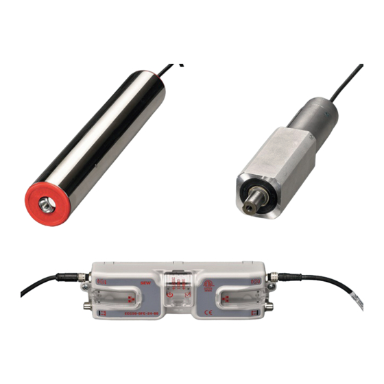
Device structure Overview of the roller drives Overview of the roller drives 3.2.1 ECR roller drive 19809722123 [1] Electrical connection [2] Axis journal [3] Motor roller Nameplate 19516478219 Type designation, e.g.: ECR-A2M-50-450-045-Z-B-V0 Voltage Serial number ® Operating instructions – ECDriveS... -
Page 15: Ecg Gearmotor
Device structure Overview of the roller drives 3.2.2 ECG gearmotor 19809719179 [1] Electrical connection [2] Gearmotor [3] Motor shaft Nameplate 19516434699 ® Operating instructions – ECDriveS... -
Page 16: Overview Of The Hardware Of The Ecc-Dbc Binary Control
Device structure Overview of the hardware of the ECC-DBC binary control Overview of the hardware of the ECC-DBC binary control ECC-DBC-24-00 24 V 25852264587 Removable feed-in terminal 24 V Removable I/O terminal strip LED “Overtemperature” Operation LED DIP switch LED "Start" LED "Hold"... -
Page 17: Installation
Installation Mechanical installation Installation Mechanical installation 4.1.1 Mounting the ECR roller drive CAUTION Improper fixation of the axis can destroy the motor roller. Possible damage to property. • Make sure not to damage the cable during assembly. • Ensure the correct torque for the screw connections. •... - Page 18 Installation Mechanical installation Continue with cable side: 19844223243 M12 flange nut Axis 5. Screw the flange nut [1] from outside onto the axis [2] on the cable side. 6. Grip axis [2] from inside with a suitable tool and tighten the flange nut [1] with a tightening torque of 50 Nm.
- Page 19 Installation Mechanical installation Continue with opposite side: 19520502923 Profile hole Spring axis 3. Press spring axis [2] inwards on the opposite side and insert the motor roller into the conveyor. 4. When the motor roller reaches its proper position on the profile hole [1], release spring axis [2].
-
Page 20: Mounting The Ecg Gearmotor
Installation Mechanical installation 4.1.2 Mounting the ECG gearmotor CAUTION Sharp edges due to open keyway. Cuts. • Insert the key into the keyway. • Pull a protective tubing over the shaft. 4 x M5 19516487947 Proceed as follows: 1. Place the gearmotor onto the carrier plate. 2. - Page 21 Installation Mechanical installation ECC-DBC-24-00 19852798219 Mounting holes Ø 6 mm 19852794507 [1] Frame of the conveyor belt [2] Binary control with metal plate as heat sink ® Operating instructions – ECDriveS...
-
Page 22: Electrical Installation
Installation Electrical installation Electrical installation 4.2.1 General information The motor roller’s input end of the shaft and/or the mounting bracket must be electri- cally connected with the grounded frame of the conveyor belt. WARNING Risk of crushing if the drive starts up unintentionally. Severe or fatal injuries. -
Page 23: Grounding Of Switched-Mode Power Supply
Installation Electrical installation 4.2.3 Grounding of switched-mode power supply According to the requirements for a SELV system, the mass connections of the output channels must be connected with the ground potential of the switched-mode power supply (SMPS). 25884830987 Switched-mode power supply If several switched-mode power supplies are connected in parallel, the mass connec- tions of at least one device must be grounded. - Page 24 Installation Electrical installation Removable I/O terminal strip [2] This is a removable 5-pin connector with screw terminals. Cable sizes are within the range of 0.4 mm and 1.5 mm (28 AWG and 16 AWG). 19853478795 Provides +24 V output voltage if error state is active +24 V input voltage activates speed control (see section Run A and Run B) +24 V input voltage activates speed control (see section Run A and Run B) At an input voltage of +24 V, the motor runs against the direction selected on...
-
Page 25: Wiring Diagrams
Installation Electrical installation 4.2.5 Wiring diagrams For the terminal assignment of the feed-in terminal and the I/O terminal strip, refer to chapter "Terminal designation" (→ 2 23). PNP module with RUN/REVERSE wiring ECC-DBC-24-00 DC 24 V 19886800779 As a requirement for the direction of rotation reversal using the "reverse" input, "RUN A"... -
Page 26: Startup
Startup General information Startup General information WARNING Risk of crushing if the drive starts up unintentionally. Severe or fatal injuries. • Before you start working on the unit, disconnect the motor and all connected op- tions from the power supply. •... -
Page 27: Dip Switches 1 To 5: Roller Speed
Startup Setting the DIP switches DIP switch Function Button position Selection acceleration/de- See section DIP switches 7 to 10: Roller celeration acceleration/deceleration 5.2.1 DIP switches 1 to 5: Roller speed Motor speed in min 1000 1200 1400 1600 1800 2000 2200 2400 2600 2800 3000... -
Page 28: Dip Switches 7 To 10: Roller Acceleration/Deceleration
Startup Setting the DIP switches 5.2.2 DIP switches 7 to 10: Roller acceleration/deceleration acceleration/deceleration time in s 0.05 x = ON - = OFF Notice: The specified time in seconds applies to the acceleration and to the decelera- tion. ® Operating instructions – ECDriveS... -
Page 29: Controlling The Roller Speed
Startup Controlling the roller speed Controlling the roller speed To calculate the roller speed based on the motor speed selected on DIP switch switches 1 to 5, the diameter of the respective roller as well as the gear unit reduction ratio of the motor roller must be known. -
Page 30: Operation
Operation Status and error statuses Operation Status and error statuses ECC-DBC-24-00 24 V 25852351627 LED "Stop" LED "Hold" LED "Start" Operation LED LED "Overtemperature" The following table lists all LEDs with their main functions. LED LED status Description 0.2 seconds of flashing at an Motor roller is not connected interval of 0.4 seconds Flashing at an interval of 1... -
Page 31: Inspection/Maintenance
Inspection/maintenance Storage Inspection/maintenance WARNING Risk of crushing if the drive starts up unintentionally. Severe or fatal injuries. • Before you start working on the unit, disconnect the motor and all connected op- tions from the power supply. • Secure the motor against unintended power-up. CAUTION The surfaces on the drive can be very hot during operation. -
Page 32: Technical Data
Technical data Technical data of the ECR roller drive Technical data Technical data of the ECR roller drive 8.1.1 Electrical data ECR-A2M-.. Voltage: DC 24 V Nominal mechanical output power at 25 °C: 40 W Nominal current: 2.5 A Maximum starting current: 7.2 A Ambient temperatures: -10 °C –... -
Page 33: Pulses Per Revolution
Technical data Technical data of the ECG gearmotor 8.2.2 Pulses per revolution Nominal gear ra- Real gear ratio Pulses per revolution Gear unit back- lash in degrees 67.22 2009 45.00 1350 32.94 27.00 18.33 15.00 10.98 9.00 1) Infinite gear unit ratio (67.22 = 67 2/9, 18.33 = 18 1/3) ®... -
Page 34: Technical Data Of The Ecc-Dbc Binary Control
Technical data Technical data of the ECC-DBC binary control Technical data of the ECC-DBC binary control Connection voltage DC 24 V +15%/-25% Voltage range on control DC 14 ‑ 30 V input Current consumption ≈ 30 mA without motor roller Integrated Max. peak current 16 A current limiting Max. - Page 40 SEW-EURODRIVE—Driving the world SEW-EURODRIVE GmbH & Co KG Ernst-Blickle-Str. 42 76646 BRUCHSAL GERMANY Tel. +49 7251 75-0 Fax +49 7251 75-1970 sew@sew-eurodrive.com www.sew-eurodrive.com...
Need help?
Do you have a question about the ECDriveS Series and is the answer not in the manual?
Questions and answers