
Related Manuals for Grundfos Multilift MSS


Summary of Contents for Grundfos Multilift MSS
- Page 1 GRUNDFOS INSTRUCTIONS Multilift MSS Installation and operating instructions Other languages http://net.grundfos.com/qr/i/98042530...
-
Page 2: Table Of Contents
Guidelines for installation of lifting station Recommended steps for mechanical installation of 2. Scope of delivery lifting station Grundfos Multilift MSS lifting stations are supplied complete with Installation of LC 220 controller collecting tank, pump, level sensor, non-return valve (depending Location on type) and LC 220 controller. -
Page 3: General Description
The lifting stations are capable of pumping liquids containing fibres, textiles, faeces, etc., below sewer level from minor buildings such as private dwellings, flats, holiday homes etc. Do not pump rainwater with the Multilift MSS lifting stations for these two reasons: •... -
Page 4: Lifting Station
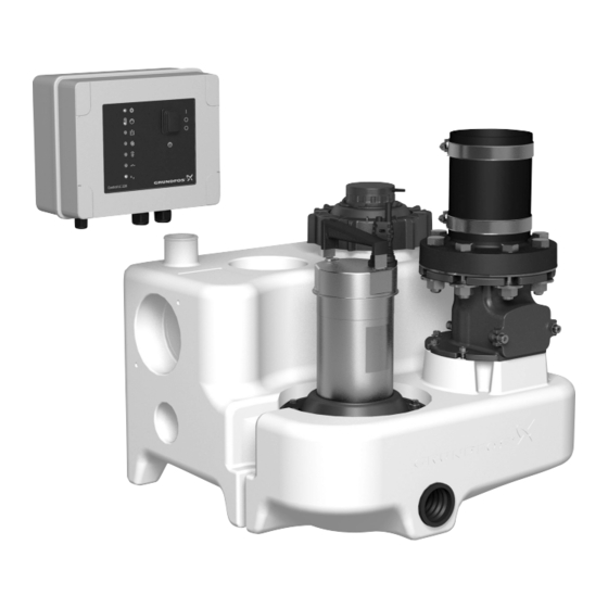
5.1 Lifting station 5.1.1 Collecting tank The gas-, odour- and pressure-tight collecting tank is made of The Grundfos Multilift MSS lifting stations are supplied complete wastewater resistant polyethylene (PE) and has all necessary with single- or three-phase submersible pumps connected to the ports for the connection of inlet pipes, outlet pipe, venting pipe LC 220 controller incorporating a level sensor. - Page 5 Nameplate, pump 5.1.4 Level sensor The nameplate is printed on the pump. The piezoresistive pressure sensor placed in the controller is connected via a hose to a pressure tube in the tank. The screw cap where the hose is connected includes a connection for a DN 100 tube.
-
Page 6: Lc 220 Controller
Furthermore, it has a level input which is activated directly via the for flood detection outside the Multilift MSS. Lifting stations are pressure tube inside the collecting tank. Finally, it has terminals... - Page 7 5.2.2 Control elements and indicator lights The table below gives a description of the function of the various control elements and indicator lights: Element Function Description The operating mode is selected by the ON-OFF-AUTO selector switch which has three different positions: POS I: Starts the pump manually.
- Page 8 5.2.3 Internal layout of LC 220 Figure shows the internal layout of LC 220. Note: Cable connection for pos. 10: Use a cable tie if leads protrude more than 20 mm from the cable sheath. HIGH 82 81 Fig. 9 Internal layout of LC 220 Pos.
-
Page 9: Installation Of Lifting Station
6. Installation of lifting station 6.1 General description Before installing the Multilift MSS lifting station, make sure that all local regulations covering venting, access to the stations, etc. are observed. 6.1.1 Installation sketch Fig. 10 Installation sketch Pos. Accessories Product number... -
Page 10: Guidelines For Installation Of Lifting Station
6.2 Guidelines for installation of lifting station 6.3 Recommended steps for mechanical installation of lifting station Guidelines for correct mechanical installation of lifting station according to EN 12056-4 1. Checking the scope of delivery. For scope of delivery, see section 2. -
Page 11: Installation Of Lc 220 Controller
5. Connecting the outlet pipe. 7. Installation of LC 220 controller Install an isolating valve between the non-return valve and the supplied flexible connection hose, DN 100 (internal diameter Warning 110 mm). A flexible connection can be ensured if a distance of Before making any connections in LC 220 or working approx. -
Page 12: Electrical Connection
7.3 Electrical connection • Switch 2 (automatic alarm reset): Warning Pos. Description The protective earth (PE) of the power outlet must be The fault indication will be reset after the fault has connected to the protective earth of the product. The disappeared, meaning the indicator lights will be turned plug must have the same PE connection system as to off and the alarm signals to external alarm devices... -
Page 13: Wiring Diagrams
3. Switch on the power supply. 4. Activate a sanitary appliance connected to the inflow of the Multilift MSS and monitor the increasing water level in the tank up to the start level. Check the starts and stops at least twice, and then change the ON-OFF-AUTO selector switch to automatic mode. -
Page 14: Maintenance And Service
• Cable entry tank. Reconnect the hose to the controller. Make sure that the cable entry is watertight and that the 7. Check the sensor by test running Multilift MSS. cables are not bent sharply and/or pinched. • Pump parts Check that the vent hole of the pump housing is clear by dismantling the pump from the support flange. -
Page 15: Fault Finding
The lifting station is undersized. Recalculate the inflow parameters and compare the result with the tank volume and pump performance. If you need a new product, contact the nearest Grundfos sales company. 3. The pump starts and a) The level sensor is blocked. -
Page 16: Technical Data
This product or parts of it must be disposed of in an environmentally sound way: 1. Use the public or private waste collection service. 2. If this is not possible, contact the nearest Grundfos company or service workshop. The crossed-out wheelie bin symbol on a product means that it must be disposed of separately from household waste. - Page 17 Appendix 1. Dimensional drawings 1.1 Multilift MSS, with non-return valve...
- Page 19 BOMBAS GRUNDFOS DO BRASIL Turkey Siu Wai Industrial Centre GRUNDFOS Pumper A/S Av. Humberto de Alencar Castelo Branco, GRUNDFOS POMPA San. ve Tic. Ltd. Sti. 29-33 Wing Hong Street & Strømsveien 344 Gebze Organize Sanayi Bölgesi CEP 09850 - 300...
- Page 20 98042530 1218 ECM: 1217058 www.grundfos.com...
Need help?
Do you have a question about the Multilift MSS and is the answer not in the manual?
Questions and answers