Table of Contents
Advertisement
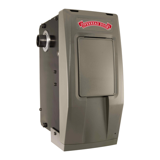
RESIDENTIAL WALL MOUNT OPENER
INSTALLATION, PROGRAMMING, OPERATION,
TROUBLESHOOTING & MAINTENANCE MANUAL
DO NOT use photocells from other manufacturers or openers with this opener.
INSTALLER: LEAVE THIS MANUAL WITH HOMEOWNER
HOMEOWNER: SAVE THIS MANUAL FOR FUTURE REFERENCE
To reduce the risk of injury to persons or damage to property, use this opener only
with a residential sectional door with front torsion springs.
Pour réduire le risque de blessures corporelles ou de dégâts matériels, utilisez cet ouvre-porte uniquement avec
une porte sectionnelle résidentielle munie de ressorts de torsion avant.
SERIAL NUMBER DECAL
© 2019 Overhead Door Corporation. Overhead Door, the Ribbon logo, Infinity, CodeDodger, OHD Anywhere, and Safe-T-Beam are registered trademarks of
Overhead Door Corporation. Overhead Door Corporation. All other trademarks are the property of their rightful owners. Consistent with our policy of continuing
product improvements, without notice or obligations. HomeLink is a registered trademark of Gentex Corporation. Car2U is a registered trademark of Lear
Corporation.
Bluetooth is a registered trademark of SIG.
INFINITY™ 2000
WARNING
!
AVERTISSEMENT
!
iDCM SERIAL NUMBER DECAL
40686503927, 07/2019
Advertisement
Table of Contents
Troubleshooting

Related Manuals for Overhead door INFINITY 2000


Summary of Contents for Overhead door INFINITY 2000
- Page 1 © 2019 Overhead Door Corporation. Overhead Door, the Ribbon logo, Infinity, CodeDodger, OHD Anywhere, and Safe-T-Beam are registered trademarks of Overhead Door Corporation. Overhead Door Corporation. All other trademarks are the property of their rightful owners. Consistent with our policy of continuing product improvements, without notice or obligations.
-
Page 2: Table Of Contents
INDEX SAVE THESE INSTRUCTIONS Section Information Page READ AND FOLLOW ALL INSTRUCTIONS Standard & Safety Features: .........................1 FCC Part 15.21 Statement: Safety & General Information: Changes or modifications not expressly Introduction ..................2 approved by the party responsible for Safety Notifications ................2 compliance could void the user’s authority to Important Installation Instructions ..........3 operate the equipment. -
Page 3: Standard & Safety Features
STANDARD AND SAFETY FEATURES Vehicle Compatible 1. Safe-T-Beam® (STB) Non-Contact Reversing System: • Places an infrared beam across the door opening. • Only affects the DOWN travel of the door. • Stops an open door from closing or reverses a door while in the down travel. • Reversing system can be overridden with constant pressure on the wired wall console only. -
Page 4: Safety & General Information: Introduction
SAFETY NOTIFICATIONS & INSTRUCTIONS OVERVIEW OF POTENTIAL HAZARDS READ THIS SAFETY INFORMATION Garage doors are large, heavy objects that move with the help of springs under high tension and electric motors. Since moving objects, springs under tension, and electric motors can cause injuries, your safety and the safety of others depend on you reading the information in this manual. If you have questions or do not understand the information presented, call your nearest trained door system technician or visit our website at www.overheaddoor.com CONVENTIONS USED IN THESE INSTRUCTIONS The following safety alert symbol and signal words are used throughout this manual to call attention to and identify different levels of hazards and special... -
Page 5: Important Installation Instructions
TO REDUCE THE RISK OF SEVERE INJURY OR DEATH READ AND FOLLOW ALL SAFETY, INSTALLATION AND OPERATION INSTRUCTIONS. If you have any questions or do not understand an instruction, call Overhead Door Corporation. • READ AND FOLLOW ALL SAFETY, INSTALLATION AND OPERATION INSTRUCTIONS. If you have any questions or do not understand an instruction, call Overhead Door Corporation. -
Page 6: Pre-Installation Considerations
PRE-INSTALLATION CONSIDERATIONS Compatibility Considerations: The Infinity 2000 Residential Wall Mount opener is intended for use on: • Standard lift up to 14 feet tall, using industry standard APCO 400.8 , 400.12 and 5250.18 drums or equivalent. • Hi-lift sectional doors up to 14 feet tall and 84 inches maximum of high lift using industry standard APCO 400.54 , 5250.54 and 500.84 drums or equivalent. -
Page 7: Pre-Installation Permanent Input Wiring
PRE-INSTALLATION CONSIDERATIONS (INPUT POWER WIRING OPTIONS) If a 115V power outlet is not available within 5 feet from bottom of the opener when mounted to door, as an option the Alternate Low Voltage Power Kit may be used (See section 9). This task should be performed prior to mounting opener. -
Page 8: Installing Cable Keepers
INSTALLING CABLE KEEPERS WARNING AVERTISSEMENT Faire fonctionner une porte avec des câbles de levage à Operating a door with frayed or broken counterbalance lift contrepoids effilochés ou cassés peut entraîner des blessures cables can result in severe or fatal injury. graves, voire mortelles. -
Page 9: Installing Opener
INSTALLING THE OPENER 1) CLOSE DOOR. 2) Remove bolt and lock washer (A) from powerhead chassis and loosely install mounting bracket from kit bag on desired side of powerhead. (Right Hand mount shown) NOTE: Bracket can be mounted to opener on either side depending on mounting requirements. 3) Slide coupler (1-1/4”... - Page 10 INSTALLING THE OPENER (CONT’) 5) Mount opener to door shaft. If the door shaft is NOT keyed, slide opener assembly onto door shaft and tighten setscrews finger tight. If the door shaft IS keyed, insert provided key into either keyway. Pull emergency release cable at the bottom of the opener to allow free rotation of the output shaft to “clock”...
- Page 11 INSTALLING THE OPENER (CONT’) 6) Mount opener to wall. Level and square opener. NOTE: Vertical lift openers will not be level. Mark mounting bracket hole position, pre-drill a 3/16” pilot hole and install lag screw and fully tighten. Add 1 full turn to hollow tube or 1/2 turn for solid shaft on each coupler set screw in 1/4 turn increments after contacting door and opener shaft surfaces.
-
Page 12: Installing Door Lock
INSTALLING THE DOOR LOCK Door lock prevents manual door operation and is important for garage security Door lock should be installed no more than 10 feet away on the opener side of the door if possible. 1. Mount door lock onto door track above a roller on the second or third door panel from the floor. If mounting position does not line up with pre-punched door lock bar cutouts as shown below: • Remove template from the back page of the owners manual. -
Page 13: Wire Door Lock
WIRE THE OPENER Wire Door Lock 1. Plug door lock harness into the LOCK plug on bottom of opener. Insert plug in correct direction (SEE INSET) 2. Run wire down the wall to the DOOR LOCK and secure with supplied wire staples. NOTE that DOOR LOCK wires are polarity sensitive. -
Page 14: Install And Wire Safe-T-Beam
WIRE THE OPENER (CONT’) Install and Wire Safe-T-Beams® (STB) 1. Position Safe-T-Beam (STB) Transmitter and Receiver on each side of garage door 5"- 6" above floor. Face ® the lenses towards each other. 2. Mark bracket mounting holes; drill 3/32" pilot holes and secure with 1/4" x 1-1/4" lag screws (provided) into wood. -
Page 15: Install Wireless Wall Console
FINISHING THE INSTALLATION Install Wireless Wall Console 1. Determine mounting location for wireless wall console. 2. Mount console no less than 5 feet above floor to prevent small children from activating opener. Open cover and remove 3. Pre-drill 3/32” holes for mounting screws, or 3/16” if using drywall anchors battery tab before programming (supplied) if needed. -
Page 16: Install And Wire Optional Wired Wall Console
FINISHING THE INSTALLATION Install and Wire Basic Wall Console (Hardwired) - Optional 1. Route supplied wire from powerhead to the desired location for the hardwired wall control. Secure wire with insulated staples. 2. On the powerhead: Remove 1/4" insulation from white and striped wire. Using a small flat head screwdriver, press in the orange tab and insert the white wire into BWC WHITE terminal and the striped wire into BWC BLACK terminal. -
Page 17: Apply Power To Opener
FINISHING THE INSTALLATION Apply power to opener CAUTION DO NOT run opener until travel limits have been set to avoid damage to unit. CAUTION NE PAS faire fonctionner l’ o uvre-porte au-delà des limites de parcours pour ne pas endommager l’unité. WARNING Opener is equipped with grounded electrical plug for your protection, and only fits grounded electrical outlets. -
Page 18: Programming Opener And Accessories: Introduction
OPENER PROGRAMMING & ACCESSORY INSTALLATIONS NOTE: Before programming the opener, check to make sure there are no objects in the garage door opening. DO NOT allow persons to enter the area of the door while programming and operating. The following steps list the order of programming the opener’s functional settings as well as installation of any accessories that were included with the opener or purchased separately. -
Page 19: Adjusting For Drum Selection
ADJUSTING FOR DRUM SELECTION WARNING AVERTISSEMENT Operator drum selection settings must be Les réglages de sélection du tambour par l’opérateur doivent être ajustés pour une utilisation sur des portes rés- adjusted for use on Standard or High Lift identielles à levage régulier ou élevé avec des diamètres de residential doors with drum diameters greater tambour supérieurs à... -
Page 20: Setting Down Limit
PROGRAMMING THE DOWN LIMIT WARNING AVERTISSEMENT • Make sure doorway is in full view and clear of obstacles and • S’assurer que le passage de la porte est visible et dégagé, à savoir people to avoid injury or property damage. sans obstacles ni personne afin d’éviter toute blessure potentielle • DO NOT operate this unit from the wall control before LIMITS are ou dommage matériel. -
Page 21: Setting Up Limit
PROGRAMMING THE UP LIMIT Programming UP Limit: HOLD 1-2. Enter Programming Mode UNTIL 1. Press and hold the UP arrow button on the opener for 2-5 seconds. Lights • The LONG LED will turn BLUE. Release button. ROUND • The LED will then flash BLUE. -
Page 22: Setting Force Control And Contact Reverse
PROGRAMMING FORCE PROFILE & CONTACT REVERSE IMPORTANT NOTICE THIS STEP MUST BE PERFORMED FOR PROPER Contact Reverse Test OPERATION! NOTE: The limit and Force settings MUST BE COMPLETED before • Operate opener 2 full cycles up and down to set performing the Contact Reverse Test. -
Page 23: Programming Additional Remote Controls
PROGRAMMING ADDITIONAL REMOTE CONTROLS 1. Activate Remote THE REMOTE CONTROLS INCLUDED WITH THIS OPENER HAVE BEEN PROGRAMMED AT THE FACTORY FOR YOUR CONVENIENCE. NOTE: The following instructions are for remote control transmitters purchased separately (In addition to those provided with this opener) but can also be used if remote(s) require re-programming. -
Page 24: Programming Accessories
PROGRAMMING ACCESSORIES (ABBREVIATED) QuickView Single Door setup. STEP 3) OPERATING THE KEYPAD WITH THE OPENER Please see complete instructions that accompany keypad Single Door Operation: 1. Ensure number pad back lighting is off. Activate keypad by opening battery 2. Enter PIN number. compartment and pull protective 3. -
Page 25: Programming Vehicle Controls
PROGRAMMING VEHICLE CONTROLS (ABBREVIATED) Programming HomeLink® System Step 1 Clear HomeLink Clear HomeLink by pressing and holding down the first and third buttons until the indicator on the HomeLink blinks slow and then fast for 22 seconds; then release both buttons. NOTE: Clearing the HomeLink will remove all previously programmed garage door openers. - Page 26 A. Press and hold buttons 1 & 3 for ONE SECOND and release all three LEDs will light solid red. B. Press and hold the button (2 or 3) to change it to a Genie® or Overhead Door® Opener, corresponding LED will flash.
-
Page 27: Programming Ohd Anywhere
PROGRAMMING OHD Anywhere® Perform these steps only after opener is fully installed, programmed and tested. IMPORTANT SAFETY INSTRUCTIONS CONSIGNES DE SéCURITé IMPORTANTES AVERTISSEMENT WARNING TO REDUCE THE RISK OF SEVERE INJURY OR DEATH, READ POUR RéDUIRE LE RISQUE DE BLESSURES GRAVES AND FOLLOW ALL INSTRUCTIONS. - Page 28 Set up opener(s) Add users Set rules and notifications. For help at any time contact The Overhead Door Corporation at 1-866-599-4995 or visit our website. www.overheaddoor.com Scan the OHD Anywhere® QR Code on the front of this manual or on the powerhead when prompted by the RESIDENTIAL WALL MOUNT OPENER INSTALLATION, PROGRAMMING, OPERATION &...
-
Page 29: Special Installation Information
SPECIAL INSTALLATION INFORMATION CHANGING FORCE SETTINGS WARNING AVERTISSEMENT Pour éviter les blessures ou des dommages TO AVOID INJURY OR DAMAGE • NE JAMAIS régler la force pour compenser des • NEVER adjust the force settings to adjust for damage, dommages, y compris une porte mal équilibrée, un rail including an unbalanced door, binding door track or de porte coinçant ou des ressorts cassés. -
Page 30: Clearing Remote/Accessory Memory
SPECIAL INSTALLATION INFORMATION CLEARING MEMORY OF REMOTE CONTROLS 1. Enter Programming Mode NOTE: Clearing memory of remotes from the powerhead will clear ALL programmed remotes, wireless keypads and vehicle transmitters. The opener will no longer recognize any signal from any remote device, including a missing remote device. This does not include the OHD Anywhere®... -
Page 31: Locating Safe-T-Beam® (Multiple Doors)
Installing Safe-T-Beams® on multiple garage doors (Preventing “cross-talk”) Multiple Garage Doors LOCATING SAFE-T-BEAM® for multiple doors • NEVER position Safe-T-Beam® modules where signals will Transmitter (RED LED) and Receiver (GREEN LED) cross. • Place the Transmitter (Red LED) Safe-T-Beams on adjacent doors facing in opposite directions. NOTE: Direct sunlight creates interference with Safe- T-Beam Receiver (Green LED). -
Page 32: Installing Battery Back Up
Installing the Battery Back-up (BBU) AC power must be present to set limits. DO NOT attempt to set limits or any other programming steps from battery power only. 1. Unplug power from opener. 2. Remove two screws securing bottom cover to opener head and remove cover. 3. -
Page 33: Adding And Programming Additional Accessories
Programming Additional Accessories The original wireless wall console and light kits are pre-programmed from the factory. However, if adding an additional WIRELESS WALL CONSOLE or LIGHT FIXTURE to this unit or either original require reprogramming for any reason, follow the instructions below. • WIRELESS WALL CONSOLE 1. -
Page 34: Maintenance
MAINTENANCE IMPORTANT SAFETY INSTRUCTIONS WARNING To reduce the risk of severe injury or death, read and follow all instructions. NEVER let children operate or play with the door controls. Keep remote away from children. ALWAYS keep the moving door in sight and away from people and objects until door is completely closed. NO ONE SHOULD CROSS THE PATH OF THE MOVING DOOR. -
Page 35: Regular Maintenance Schedule
Regular inspection/maintenance for the door and opener should be performed at regular intervals to ensure the system runs at peak safety, performance and efficiency. MAINTENANCE ITEM INTERVALS DETAILS See Page 20 to run system test. Contact Reverse Test Monthly Lubricate Door Hardware Monthly Lubricate Rollers &... -
Page 36: Troubleshooting & Led Signals
TROUBLESHOOTING Need help or have questions? Call Overhead Door Corporation at STOP 1-800-929-3667 or visit: www.overheaddoor.com Opener does NOT operate when wall control is pressed. • Replace Wireless Wall Console Batteries, see page 33. • If applicable, turn Sure-Lock™ OFF with Basic Wall Console, see page 14. - Page 37 TROUBLESHOOTING (CONT’) Door starts down, then STOPS before it is closed. OR Door will only open. • Check Safe-T- Beam® wire connection at powerhead and at STBs. See page 12/29, Safe-T-Beam® system check. • Check if limits are properly set, see pages 18-19. Adjust limits as needed. • Check CONTACT REVERSE, see page 20.
- Page 38 TROUBLESHOOTING (CONT’) POWERHEAD LEDS Powerhead LED Solution Possible Problem Round LED Long LED Normal operation. None required. Check power supply. No response from unit. Contact a trained door system professional. ON/RED/ ON/RED/ Limits NOT set properly. Re-program limits, see pages 18-19. STEADY STEADY Program error.
- Page 39 PARTS, SERVICE & ACCESSORIES Specify model number of opener when ordering parts DESCRIPTION PART NUMBER Hardware Bag 39946R.S Cable Keeper Kit 39794A.S Coupler 39830R.S Door Lock 40760R.S Door lock harness 40629A.S Wireless Wall Console 39774R.S Light Fixture 39945R.S Low Voltage Power Input Kit 40984R.S TorqueMaster®...
-
Page 40: Replacement Parts
REPLACEMENT PARTS Specify model number of opener when ordering parts ITEM DESCRIPTION Housing Cover Main Control Board Kit Integrated OHD Anywhere® Control Board Kit Transformer Kit Chain assembly, 16 Loop, 1/2” P Shaft Assembly Kit Motor Assembly Kit MLS (Travel Limit) Kit Release Assembly Kit Side Panel Assembly RH Side Panel Assembly LH... -
Page 42: Dasma Information
DASMA SAFETY GUIDELINES Look for this Safety Alert Symbol below. This symbol indicates a potential personal safety hazard that can result in injury or death. A GARAGE DOOR IS THE LARGEST MOVING OBJECT IN THE HOME. These doors are often operated by electric door openers. Proper installation, operation, maintenance, and testing of the garage door and automatic opener are necessary to provide safe, trouble-free operation. - Page 43 DASMA SAFETY GUIDELINES (CONT’) WHEN USING THE PUSH BUTTON OR The push button wall control should TRANSMITTER, KEEP THE DOOR IN SIGHT be out of reach of children. UNTIL IT COMPLETELY STOPS MOVING. (at least 5 feet from the floor) and Teach children never to play under or near an away from all moving parts.
- Page 44 OVERHEAD DOOR CORPORATION OPERATOR DIVISION 1 Door Drive, Mount Hope OH. 44666 1-800-929-3667 www.overheaddoor.com DOOR LOCK TEMPLATE 9/32 9/32...
Need help?
Do you have a question about the INFINITY 2000 and is the answer not in the manual?
Questions and answers
how do i change the door operation from manual to remote
To change the Overhead Door model 2000 operation from manual to remote:
1. Ensure the door is properly balanced and the springs are not broken. Do not operate manually or automatically if unbalanced or damaged. Contact a trained door technician if needed.
2. Program the remote to the opener:
- Press and hold the SET/PRGM button on the opener for 2–5 seconds until the round blue LED turns on, then release. The long purple LED will start flashing.
- Hold the remote two inches from the HomeLink button (if using HomeLink).
- Press and hold the remote button and the desired HomeLink button together until the HomeLink indicator blinks slow then fast.
- Release both buttons when blinking changes.
- The remote is now programmed to operate the opener.
This enables remote operation instead of manual.
This answer is automatically generated
how do i change thr door operation on the infinity 2000 from manual to remote