Table of Contents
Advertisement
Quick Links
Advertisement
Table of Contents

Related Manuals for Avlite AV-OL-KT-A1


Summary of Contents for Avlite AV-OL-KT-A1
- Page 1 AV-OL-KT-A1 Obstruction Lighting Kit FAA - A-1 INSTALLATION & SERVICE MANUAL V1.0...
- Page 2 Version No. Description Date Reviewed Approved Design AV-OL-KT-A1 Manual Launch September 2019 P. Naidu W. Evans M. Sugars...
-
Page 3: Table Of Contents
7.2.2 Additional Tools Required ......................20 7.2.3 Cabling Requirements....................... 20 7.2.4 Factory Settings ..........................20 7.2.5 Installation Recommendation ....................20 7.3 Testing Procedure ...........................37 Maintenance and Servicing ................. 38 Replacement Parts ....................38 10.0 Troubleshooting ..................... 39 Latest products and information available at www.avlite.com... -
Page 4: Introduction
Avlite Systems draws on more than 25 years of experience in the design and manufacture of navigation aids, and particular care has been taken to ensure your light gives years of trouble-free service. -
Page 5: Technology
LED Technology All Avlite lights use the latest advancements in LED (Light Emitting Diode) technology as a light source. The major advantage of LED’s over traditional light sources is well established in that they typically have an operational life in excess of 100,000 hours, resulting in substantial savings to maintenance and servicing costs. -
Page 6: Av-Ol-Kt-A1 Models
3.0 AV-OL-KT-A1 The AV-OL-KT-A1 Obstruction Lighting Kit integrates Avlite’s world class LED fixtures with an application specific control and monitoring system to provide a full turnkey solution for A1 defined structures ranging between 150 and 350 feet (45-106 meters). These include telecommunication towers and utility towers, wind turbines, cranes, buildings and other tall structures. - Page 7 ECR No. Note: Mounting hardware not included. Standard Model Model shown with optional 1 inch pipe thread adapter 20in 20in 508mm 508mm 18.5in [15.8in] [7.9in] 18.5in 470mm 400mm 200mm 470mm 10.3in 10.3in 261mm 261mm Latest products and information available at www.avlite.com...
- Page 8 1 x Top Level Junction Box Note: Mounting hardware not included. Model Zone Description Date:- Drawn:- Approved:- ECR No. [7.74in] [4.86in] 197mm 123mm Model Zone Description Date:- ECR No. General Tolerances Linear Angular Radii ±1.2 ±1.0° ±2.0 ±0.3 ±0.5° ±0.5 X.XX ±0.1 002210-001-000...
-
Page 9: Available Options
The system can also be configured to send out SMS text messages or e-mail alerts to designated operators should alarm conditions be triggered, such as low voltage or light failure. Please contact Avlite for operational information for the Monitoring & Control options. Visit https://www.star2m.com to find out more about Star2M •... -
Page 10: Av-Ol-Kt-A1 Data Sheet
L-864 Medium Intensity Obstruction Light, L-810(F) Low Intensity Obstruction Light (Qualified by Intertek) Intellectual Property Trademarks AVLITE is a registered trademark of Avlite Systems ® Warranty * 5 year warranty on light fixtures 3 year warranty on Control Unit Options Available •... -
Page 11: Safety Information
Do not stare at the LED or shine the LED into your eyes or those of another person. • Dispose of the product according to the local laws and regulations for your region, for example, at a recycling centre that accepts electronic devices. Latest products and information available at www.avlite.com... -
Page 12: Operation And Setup
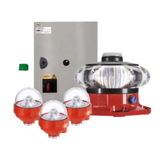
6.0 Operation and Setup Avlite’s A1 Obstruction Lighting Solution Kit consists of five components: A Control Unit which provides power, day & night control and (optional) remote monitoring, a single L-864 red Medium Intensity obstruction beacon, and three L-810(F) red obstruction lights. -
Page 13: L-864
Once the Flat Battery cut-off condition is in effect, the lantern will not turn back on until it sees day light and the battery voltage is above the “OK” threshold for at least one minute. Latest products and information available at www.avlite.com... - Page 14 YELLOW Status LED Lantern Status Lantern Condition Standby Lantern is in Standby Mode Quick Flashing Day To Night Transitioning Light is activating and will turn 0.15s on, 0.15s (Dusk Till Dawn Mode) on after detecting 30 seconds of continuous darkness 2 Quick Operational, Not Lantern is in Normal operating...
-
Page 15: L-810(F)
To return to the Auto mode, return the switch to the Auto position. Note: Time delays are to be expected when changing modes. Allow up to 1 minute to change between functions. Latest products and information available at www.avlite.com... -
Page 16: T2 Controller
6.1.4 Interface Wiring L-864 L-864 Top Junction Top Junction L-810(F) L-810(F) L-810(F) L-810(F) L-810(F) L-810(F) Middle Middle Junction Box Junction Box Power & Data cable: Power & Data cable: Power & Data cable: Power & Data cable: 5 x 18 AWG 5 x 18 AWG 5 x 18 AWG 5 x 18 AWG... -
Page 17: Interface Wiring
Installation & Service Manual 6.1.5 GPS Synchronisation Avlite has utilized the latest advancements in GPS technology to develop an internal synchronization system that is incorporated into the lights. Using overhead satellites, multiple obstruction lights set to the same flash pattern will flash in unison. No additional... -
Page 18: Unpacking, Installation, Wiring And Setup
7.0 Unpacking, Installation, Wiring and Setup 7.1 Unpacking Unpack all hardware and inspect for damage. If there is any damage, please contact your Avlite Office. Retain original packing material for possible future use in shipping. 7.2 Installation WARNING: Confirm that the power switch is toggled to the OFF position when power is connected. -
Page 19: Tools Required
Junction Boxes (2) (owner supplied or optional purchase) Light Mounting Brackets (4) (optional purchase) Cables (owner supplied or optional purchase) 7.2.2 Location Refer to FAA AC 150/5345-43 and FAA AC 70/7460-1L for site requirements for obstruction lights. Latest products and information available at www.avlite.com... -
Page 20: Additional Tools Required
7.2.3 Cabling Requirements The installation of the AV-OL-KT-A1 Obstruction Lighting Kit requires the following cables (if optional cable kit is not purchased): Reference Point Cable L-864 -Top Junction Box • Power Cable: 10 AWG 2 Conductor. • Data Cable: 18 AWG 4 Conductor. - Page 21 Mount the Control Unit (with the previously attached mounting hardware) to the tower or installation structure using the mounting tabs. Secure using the required mounting fixtures. Note: Mounting hardware is not included with the kit. Latest products and information available at www.avlite.com...
- Page 22 Mount External Photocell Insert the Photocell into the mount (Avlite supplied) by inserting the contact blades into the receptacle. Secure the Photocell assembly to the tower or installation structure using the required mounting fixtures. The following considerations should be taken into account when mounting the external Photocell: •...
- Page 23 -Common’ labelled terminal on terminal block 1 in the Control Unit • Connect the green Photocell signal conductor to the ‘PC Signal’ labelled terminal on terminal block 1 in the Control Unit Refer to section 7.2.3 Cabling Requirements for recommended cable sizes. Latest products and information available at www.avlite.com...
- Page 24 Mount the L-864 Medium Intensity Obstruction light directly to the top of the tower or installation structure either by securing it to the mounting plate or by attaching an optional Avlite Right Angle Pole Mounting Bracket (for medium intensity fixtures) to the tower and bolting the L-864 to the bracket.
- Page 25 • • • • Run two cables from the top junction box to the Control Unit, one for power and one for data. Refer to section 7.2.3 Cabling Requirements for recommended cable sizes. Latest products and information available at www.avlite.com...
- Page 26 Route top junction box to control unit cables Wiring instructions-Power Cable: • Connect the black positive conductor from the +48VDC terminal in the top-level junction box to circuit breaker 2 (label ‘L-864 +24VDC’) on terminal block 1 in the Control Unit. •...
- Page 27 AV-OL-KT-A1 - Obstruction Light Kit Installation & Service Manual Latest products and information available at www.avlite.com...
- Page 28 Route top junction box to control unit cables Wiring instructions-Data Cable: • Connect the white Alarm Common (COM) conductor from the top-level junction box to the ‘L-864 Alarm Common’ labelled terminal on terminal block 1 in the Control Unit • Connect the black alarm signal (NC) conductor from the top-level junction box to the ‘L-864 Alarm Signal’...
- Page 29 AV-OL-KT-A1 - Obstruction Light Kit Installation & Service Manual Latest products and information available at www.avlite.com...
- Page 30 Mount the L-810(F) lights (x3) Thread a ¾” pipe thread cord grip to the L-810(F) and attach the light to an owner supplied bracket or optional Avlite Right Angle Mounting Bracket (for low intensity fixtures) with a locking nut. ¾” Conduit Locknut and Nipple (Optional)
- Page 31 +VDC terminal for marker 1,2,3 or 4 (if installed) in the mid-level junction box • Connect the black negative conductor from the L-810(F) to the appropriately marked -VDC terminal for marker 1,2,3 or 4 (if installed) in the mid-level junction box Latest products and information available at www.avlite.com...
- Page 32 • Connect the orange Alarm COM conductor from the L-810(F) to the appropriately marked Alarm COM terminal for marker 1,2,3 or 4 (if installed) in the mid-level junction • Connect the Green NC conductor from the L-810(F) to the appropriately marked Alarm NC terminal for marker 1,2,3 or 4 (if installed) in the mid-level junction box...
- Page 33 Connect the White PC Input (IN1) conductor from the L-810(F) to the appropriately marked PC terminal for marker 1,2,3 or 4 (if installed) in the mid-level junction box Refer to section 7.2.3 Cabling Requirements for recommended cable sizes. Latest products and information available at www.avlite.com...
- Page 34 12. Route middle junction box to Control Unit cables Wiring instructions-Power and Data Cable: • Connect the red positive CTRL + 24VDC conductor from the middle junction box to circuit breaker 3 (i.e. Label L-810F + 24VDC) on terminal block 1 in the Control Unit •...
- Page 35 AV-OL-KT-A1 - Obstruction Light Kit Installation & Service Manual Refer to section 7.2.3 Cabling Requirements for recommended cable sizes. Latest products and information available at www.avlite.com...
- Page 36 13. Wiring the Control Unit: AC Installation: Connect the incoming power conductors to the appropriate terminals (i.e. AC Line 1, AC line 2 and AC Neutral) on the power switch on terminal block 1 in the Control Unit. The grounding conductor will be connected to the ‘Ground’ labelled terminal block (green/ yellow) adjacent to the power switch.
-
Page 37: Testing Procedure
Connect the negative conductor to the common terminal block adjacent to the circuit breaker on terminal block 1. 7.3 Testing Procedure Note: Avlite recommends that all testing be done during the day. Power the system on. Check that no circuit breakers have tripped. -
Page 38: Maintenance And Servicing
Ensure Photocell is free from debris (i.e. snow, leaves, etc.) for reliable and continuous operation. 9.0 Replacement Parts If replacement parts are required, please call a local Avlite distributor and reference the Product or Configuration Code called out in the “Product Configuration and Options” section of the corresponding product data sheet. -
Page 39: Troubleshooting
Measure voltage at junction mode) • Light failure box. If correct input power, • No power to the replace light. light • If no voltage to the junction box, check output power from Control Box. Latest products and information available at www.avlite.com... - Page 40 Problem Possible Cause Solution L-810(F) middle light • Wired • Check wiring to light in middle is not operational incorrectly or junction box (others turning red wire(s) lose • Measure voltage at junction at night or photocell • Light failure box.
- Page 41 AV-OL-KT-A1 - Obstruction Light Kit Installation & Service Manual Notes Latest products and information available at www.avlite.com...
- Page 43 AV-OL-KT-A1 - Obstruction Light Kit Installation & Service Manual Latest products and information available at www.avlite.com...
- Page 44 Avlite Solution Verticals available Airfield Heliport Obstruction We believe technology improves navigation avlite.com info@avlite.com Avlite Systems Avlite USA LLC Avlite Asia Pte Ltd Australia Singapore +61 (0)3 5977 6128 +1 (603) 737 1311 +65 6908 2917...
Need help?
Do you have a question about the AV-OL-KT-A1 and is the answer not in the manual?
Questions and answers