
Related Manuals for Sungrow SG CX-US Series


Summary of Contents for Sungrow SG CX-US Series
- Page 1 User Manual PV Grid-Connected Inverter SG36_60CX-US SG36_60CX- USPV Grid-Connected InverterUser ManualSG36_60CX-US-UEN-Ver17- 202411 SG36_60CX-US-UEN-Ver17-202411...
-
Page 3: All Rights Reserved
Software Licenses • It is prohibited to use data contained in firmware or software developed by SUNGROW, in part or in full, for commercial purposes by any means. • It is prohibited to perform reverse engineering, cracking, or any other operations that compromise the original program design of the software developed by SUNGROW. -
Page 4: About This Manual
About This Manual The manual mainly describes the product information, guidelines for installation, operation and maintenance. The manual cannot include complete information about the photovoltaic (PV) system. You can get additional information about other devices at www.sungrowpower.com or on the webpage of the respective component manufacturer. Validity This manual is valid for the following inverter types: •... - Page 5 Symbol Explanation Indicates a hazard with a high level of risk that, if not avoided, will result in death or serious injury. Indicates a hazard with a medium level of risk that, if not avoided, could result in death or serious injury. Indicates a hazard with a low level of risk that, if not avoided, could result in minor or moderate injury.
-
Page 7: Table Of Contents
Contents All Rights Reserved .....................I About This Manual......................II 1 Safety .........................1 1.1 PV Panels......................1 1.2 Utility Grid ......................1 1.3 Inverter ......................2 1.4 Skills of Qualified Personnel ................3 2 Product Introduction ..................4 2.1 Intended Usage....................4 2.2 Product Introduction..................5 2.2.1 Model Description .................5 2.2.2 Appearance ..................6 2.2.3 Dimensions ..................7 2.2.4 LED Indicator Panel ................7... - Page 8 4.4.1 Manual Transport ................22 4.4.2 Hoisting Transport................23 4.5 Dimensions of mounting-bracket..............24 4.6 PV Tracker-Mounted Installation ..............25 4.6.1 Preparation Before Mounting ...............25 4.6.2 Mounting Steps...................25 4.7 Wall-Mounted Installation ................27 4.7.1 Preparation Before Mounting ...............27 4.7.2 Mounting Steps...................28 5 Electrical Connection ..................31 5.1 Safety Instructions ..................31 5.2 Terminal Description ..................31 5.3 Electrical Connection Overview ..............32...
- Page 9 5.11 Module-Level Rapid Shutdown Device Connection (Optional) ......55 5.11.1 Module-Level Rapid Shutdown System Introduction......55 5.11.2 Module-Level Rapid Shutdown Device Connection ......56 6 Commissioning ....................57 6.1 Inspection before Commissioning ..............57 6.2 Commissioning Procedure ................57 6.3 Module-Level Rapid Shutdown Commissioning (Optional) .......57 7 System Decommissioning ................59 7.1 Disconnecting the Inverter................59...
-
Page 11: Safety
The safety instructions in this manual cannot cover all the precautions that should be followed. Perform operations considering actual onsite conditions. SUNGROW shall not be held liable for any damage caused by violation of the safety instructions in this manual. -
Page 12: Inverter
1 Safety User Manual Inverter Danger to life from electric shocks due to live voltage • Do not open the enclosure at any time. Unauthorized opening will void guarantee and warranty claims and in most cases terminate the operating license. Risk of inverter damage or personal injury •... -
Page 13: Skills Of Qualified Personnel
User Manual 1 Safety Warning Label Description Label Danger to life due to high voltages! Only qualified personnel can open and service the inverter. Disconnect the inverter from all the external power sources before service! There is a danger from a hot surface that may exceed 60°C. Check the user manual before service! Skills of Qualified Personnel All installations should be performed by qualified personnel. -
Page 14: Product Introduction
Product Introduction Intended Usage SG36CX-US, SG60CX-US, a transformerless three-phase PV grid-connected inverter, is an integral component in the PV power system. The inverter is designed to convert the DC power generated from the PV modules into grid- compatible AC power and provide it to local loads or export it into the utility grid. The intended usage of the inverter is illustrated in "figure 2-1 Inverter application in PV power system". -
Page 15: Product Introduction
User Manual 2 Product Introduction Description Item Note Lift the voltage of the power to the grid level. Transformer Utility grid TN-C, TN-S, TN-C-S, TT, IT. In an IT system, the inverter does not detect AC Side Ground Faults. Only DC Side Ground Fault protection is provided by the inverter. -
Page 16: Appearance
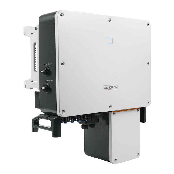
2 Product Introduction User Manual The device model can be found on the nameplate attached to the side of the inverter. For details, refer to "3.2 Identifying the Inverter". 2.2.2 Appearance *The image shown here is for reference only. The actual product you receive may differ. Description Name LED indicator... -
Page 17: Dimensions
User Manual 2 Product Introduction 2.2.3 Dimensions figure 2-2 Dimensions of the Inverter *The image shown here is for reference only. The actual product you receive may differ. Type Dimensions (W1*H1*D1) Dimensions (W2*H2*D2) Weight SG36- 702 * 595 * 310 mm (27.6'' * 231 * 295 * 234 mm (9.1'' 54kg(119.05lbs) CX-US... -
Page 18: Dc Switch
2 Product Introduction User Manual LED state Definition indicator A fault occurred and the device cannot connect to the grid. The Bluetooth communication is connected and there is data communication. Twinkling System fault occurs. Both the AC and DC sides are powered down. The inverter may carry voltage in case of fault. -
Page 19: Circuit Diagram
User Manual 2 Product Introduction Circuit Diagram The MPPT is utilized for DC input to ensure the maximum power from the PV array at different PV input conditions. The inversion circuit converts the DC power into AC power and feeds the AC power into the utility grid through the AC terminal. The protection circuit is equipped to ensure the safe operation of the device and personal safety. - Page 20 2 Product Introduction User Manual • Before enabling the PID recovery function, make sure the voltage polarity of the PV modules to ground meets requirement. If there are any questions, contact the PV module manufacturer or read its corresponding user manual. •...
-
Page 21: Unpacking And Storage
Check the delivery scope for completeness according to the packing list. Contact SUNGROW or the supplier in case there is any damage or incompleteness. Do not dispose of the original packing case. It is recommended to store the inverter in it. -
Page 22: Scope Of Delivery
3 Unpacking and Storage User Manual table 3-1 Description of Icons on the Nameplate Description Icon Do not dispose of the inverter together with household waste. Refer to the corresponding instructions. CSA (US & CA) mark of conformity. Scope of Delivery figure 3-2 Scope of Delivery a. -
Page 23: Inverter Storage
User Manual 3 Unpacking and Storage Inverter Storage Proper storage is required if the inverter is not installed immediately. • Store the inverter in the original packing case with the desiccant inside. • The storage temperature must be always between -40° C and +70° C, and the storage relative humidity must be always between 0 and 95 %, non-condensing. -
Page 24: Mechanical Mounting
Mechanical Mounting Safety During Mounting Ensure there is no electrical connection before installation. In order to avoid electric shock or other injury, be sure there is no electricity or conduit installations before drilling holes. Risk of injury due to improper handling •... -
Page 25: Installation Environment Requirements
User Manual 4 Mechanical Mounting 4.2.1 Installation Environment Requirements • The inverter produces noise during operation, thus it is not recommended to install it in places for residential purpose. If this cannot be avoided, it is recommended to install the inverter in a place over 25 meters away from the residential area, or take noise mitigation measures. -
Page 26: Carrier Requirements
• Please consult SUNGROW before installing inverters outdoors in areas prone to salt damage, which mainly are coastal areas within 500 meters of the coast. The sedimentation amount of salt spray is correlated to the characteristics of the seawater, sea winds, precipitation, air humidity, topography, and forest coverage in the adjacent sea areas, and there are substantial differences between different coastal areas. -
Page 27: Installation Angle Requirements
4 Mechanical Mounting 4.2.3 Installation Angle Requirements Inverter vertically or at a minimum back tilt of 10°. Forward installation or upside down installation is prohibited. Please consult SUNGROW before tilting backwards the inverter and install it in floating power plants. -
Page 28: Installation Clearance Requirements
The various waterproof terminals should be tightened in accordance with the torque requirements in this manual to ensure that they are tight and sealed. Contact SUNGORW if you have any question. About X-RACK ordering issues, please contact you local SUNGROW Sales or SUNGROW authorized distributors. 4.2.4 Installation Clearance Requirements •... - Page 29 User Manual 4 Mechanical Mounting * The distance can be shortened to 200mm according to onsite conditions. In case the distance is less than 450mm, remove the inverter from the mounting-bracket or wall before maintaining fans. The distance between the bottom of the inverter and the ground surface is determined according to the bending radius of the AC cable used and the installation environment.
- Page 30 4 Mechanical Mounting User Manual • In case of multiple inverters, reserve specific clearance between the inverters, as shown below. • In case of back-to-back installation, reserve specific clearance of at least 500m between the two inverters, as is shown below. •...
-
Page 31: Installation Tools
User Manual 4 Mechanical Mounting Installation Tools Installation tools include but are not limited to the following recommended ones. If necessary, use other auxiliary tools on site. table 4-1 Tool Specification Specification M2/M6 M4/M6/M8 Drill bit: φ12, φ14 Includes sleeve with opening size 16mm... -
Page 32: Moving The Inverter
4 Mechanical Mounting User Manual Specification Opening:13mm, 16mm Crimp range 4~6mm Range≥1100Vdc 15mm Moving the Inverter Move the inverter to the specified position before installation. The inverter can be moved manually or via a hoist. 4.4.1 Manual Transport Lift and move the inverter to the destination by using the side handles and bottom handles. Inappropriate moving operation may cause personal injury!... -
Page 33: Hoisting Transport
User Manual 4 Mechanical Mounting 4.4.2 Hoisting Transport Step 1 Release the sealing screws on the mounting ears and store them properly. Anchor two M12 thread lifting rings to the hangers of the inverter. Step 2 Lead the sling through the two lifting rings and fasten the tie-down strap. Step 3 Hoist the inverter, and stop to check for safety when the inverter is 100mm above the ground. -
Page 34: Dimensions Of Mounting-Bracket
4 Mechanical Mounting User Manual Step 4 Remove the lifting rings and reassemble the sealing screws removed in Step 1. Keep the inverter balanced throughout the hoisting process and avoid collisions with walls or other objects. Stop hoisting in the event of severe weather, such as heavy rain, thick fog, or strong wind. -
Page 35: Pv Tracker-Mounted Installation
User Manual 4 Mechanical Mounting PV Tracker-Mounted Installation 4.6.1 Preparation Before Mounting Tools Specification Item Phillips screwdriver/ electric M4, M6 screw driver Marker Level Drill bit: φ12 Hammer drill Including 16mm socket Socket wrench Opening: 16mm Wrench Spare parts Quantity Specification Item Source... - Page 36 4 Mechanical Mounting User Manual Step 2 Level the assembled mounting-bracket by using the level, and mark the positions for drilling holes on the PV bracket. Drill the holes by using a hammer drill. Step 3 Secure the mounting-bracket with bolts. table 4-2 Fastening sequence Components Description...
-
Page 37: Wall-Mounted Installation
User Manual 4 Mechanical Mounting Step 6 Hang the inverter to the mounting-bracket and ensure that the mounting ears perfectly engage with the mounting-bracket. Step 7 Secure the inverter with two M6×65 screws. - - End Wall-Mounted Installation 4.7.1 Preparation Before Mounting Tools Specification Item... -
Page 38: Mounting Steps
4 Mechanical Mounting User Manual Spare parts Quantity Specification Item Source Delivery scope M4×10 Grub screw Delivery scope M6×65 M10×95 Expansion bolts Self-prepared (Recommended) 4.7.2 Mounting Steps Step 1 Assemble the mounting-bracket by using the connecting bar. Step 2 Level the assembled mounting-bracket by using the level, and mark the positions for drilling holes on the installation site. - Page 39 User Manual 4 Mechanical Mounting Step 3 Insert the expansion bolts into the holes and secure them with a rubber hammer. Fasten the nut with a wrench to expand the bolt. Remove the nut, spring washer, and flat washer, and store them properly.
- Page 40 4 Mechanical Mounting User Manual Step 7 Hang the inverter to the mounting-bracket and ensure that the mounting ears perfectly engage with the mounting-bracket. Step 8 Secure the inverter with screws. - - End...
-
Page 41: Electrical Connection
Electrical Connection Safety Instructions Prior to any electrical connections, keep in mind that the inverter has dual power supplies. It is mandatory for the qualified personnel to wear personal protective equipments (PPE) during the electrical work. Danger to life due to high voltage inside the inverter! •... -
Page 42: Electrical Connection Overview
5 Electrical Connection User Manual figure 5-1 Wiring terminals * Figure shown here is for reference only. The actual product you receive may differ! Item Terminal Mark Note MC4 PV connector SG36CX-US: 8 pairs of terminals PV terminals + / - SG60CX-US: 12 pairs of terminals COM1 Communicati-... - Page 43 User Manual 5 Electrical Connection Designation Item PV string Inverter Grid Load Monitoring device table 5-1 Cable requirements Specification Cable Type Cable Diameter Cross-sectional area (mm) PV cable complying with DC cable 12~10AWG 1,500V standard Additional Outdoor single- The same as that of the PE Grounding core copper wire wire in the AC cable...
-
Page 44: Additional Grounding Connection
5 Electrical Connection User Manual Additional Grounding Connection Electric shock! • There are large currents during the inverter's operation. If the inverter is powered on and put into operation without being grounded, it may lead to electric shock hazards or failures of major protective functions such as surge protection. -
Page 45: Connection Procedure
User Manual 5 Electrical Connection 5.4.2 Connection Procedure Step 1 Prepare the cable and OT/DT terminal. 1:Heat shrink tubing 2:OT/DT terminal Step 2 Remove the screw on the grounding terminal and fasten the cable with a screwdriver. Step 3 Apply paint to the grounding terminal to ensure corrosion resistance. - - End The grounding screws have been anchored to the side of the inverter before delivery, and do not need to be prepared. -
Page 46: Ac Cable Connection
The apparent power of the inverter should never exceed the power of the transformer. The maximum AC current of all inverters connected in parallel must be taken into account. If more than 30 inverters are connected to the grid, contact SUNGROW. •... -
Page 47: Requirements For Ot/Dt Terminal
User Manual 5 Electrical Connection • The transformer is an important part of a grid-connected PV generation system. The faults tolerance capacity of the transformer should be taken into account at all times. The faults include: system short circuit, grounding fault, voltage drop, etc. •... -
Page 48: Connection Procedure
5 Electrical Connection User Manual 5.5.4 Connection Procedure Step 1 Disconnect the AC-side circuit breaker and prevent it from inadvertent reconnection by implementing a lok-out, tag-out(LOTO), in accordance with local regulations. Step 2 Use an torx wrench to remove the four screws on the AC junction box. Step 3 Use a Phillips screwdriver to remove the two screws on the transparent protective cover. - Page 49 User Manual 5 Electrical Connection Step 6 Make the cable and crimp OT terminal.
- Page 50 5 Electrical Connection User Manual Step 7 Secure the cable to corresponding terminals. Observe the terminal layout on the block. Do not connect the phase wires to "PE" terminal or PE wire to "N" terminal. Otherwise, unrecoverable damage to the inverter will occur.
-
Page 51: Dc Cable Connection
User Manual 5 Electrical Connection Step 8 Secure the transparent protective cover, and secure it with Phillips screwdriver. Step 9 Secure the cover of the AC junction box, and secure it with torx wrench. - - End DC Cable Connection Electric shock! The PV array will generate lethal high voltage once exposed to sunlight. -
Page 52: Pv Input Configuration
SG60CX-US 1000V 5.6.2 Connection Procedure SUNGROW provides corresponding plug connectors in the scope of delivery for quick connection of PV inputs. DC cables should be connected to the inverter via PV connectors which are included in the scope of delivery. - Page 53 Use MC4 DC terminals if the maximum input voltage is greater than 1,000V. To purchase the MC4 DC terminals, contact SUNGROW. • Select appropriate DC terminals as required above. Otherwise, SUNGROW shall be held no liability for the damage caused. Step 1 Strip the insulation from each DC cable by 7mm.
-
Page 54: Installing The Pv Connectors
5 Electrical Connection User Manual Step 4 Check for correct polarity. The inverter will not function properly if any PV polarity is reversed. - - End 5.6.3 Installing the PV Connectors Step 1 Rotate all the DC switches to "OFF" position. Skip performing step1 when the actual device is not equipped with DC switches. -
Page 55: Communication Junction Box
Arc or contactor over temperature may occur if the PV connectors are not firmly in place, and SUNGROW shall not be held liable for any damage caused. Step 4 Follow the foregoing steps to connect PV connectors of other PV strings. -
Page 56: Install The Junction Box
5 Electrical Connection User Manual 5.7.2 Install the Junction Box Step 1 Align the junction box with the corresponding port and push it into the port to reassemble junction box. - - End Communication Wiring Board The communication board of the inverter includes two layers. The upper layer communication board mainly includes RS485 communication interfaces while the lower layer communication board mainly includes DI/DO interface and DRM interface. -
Page 57: Rs485 Communication System
User Manual 5 Electrical Connection All three interfaces can be connected to a data acquisition device (Data Logger), to achieve data exchange with PC or other monitoring devices. The RS485-1 crimp and the RJ45 interface can be applied to applications where multiple inverters communicate in a daisy-chain form. - Page 58 5 Electrical Connection User Manual Multi-inverter communication system In case of multiple inverters, all the inverters can be connected via RS485 cables in the daisy chain manner. When more than 15 inverters are connected on the same daisy chain, the inverters on two ends of the chain should be equipped with terminal resistors of 120Ω...
-
Page 59: Connection Procedure(Crimp)
User Manual 5 Electrical Connection figure 5-4 Configuration of dip switch (N≥15) The length of the RS485 cable and twisted pair cable should be no longer than 1,200m. If multiple inverters are connected to the data logger, the number of permissible daisy chains and the number of devices allowed to be connected should meet the requirements (refer to the user manual for the data logger). - Page 60 5 Electrical Connection User Manual Step 3 Loosen the swivel nut of the junction box and select an appropriate seal according to cable outer diameter. Lead the cable through the swivel nut, seal, and junction box successively. Outer diameter D(mm) Seal 4.5~6 6~12...
-
Page 61: Connection Procedure (Rj45 Ethernet Port)
User Manual 5 Electrical Connection Step 8 Pull the cable gently to make sure it is secured, tighten the swivel nut clockwise. - - End 5.9.4 Connection Procedure (RJ45 Ethernet Port) Step 1 Remove the communication junction box, see "5.7.1 Remove the Junction Box". - Page 62 5 Electrical Connection User Manual Step 3 Strip the insulation layer of the Ethernet cable with a wire stripper, and insert the signal wires to the RJ45 connector. Crimp the RJ45 connector with a crimping tool. Step 4 Insert the RJ45 connector to the RJ45 jack. Step 5 If other wiring operations need to be performed on the communication board, finish the wiring operations before performing the following steps.
-
Page 63: Dry Contact Connection
User Manual 5 Electrical Connection 5.10 Dry Contact Connection Dry contact cables require a cross section of 18AWG~16AWG. The connection procedure of the dry contact is the same as that of the RS485 terminal block. 5.10.1 Dry Contact Function The configuration circuit board is provided with fault output dry contact and emergency shutdown dry contact, as shown in the Figure below. - Page 64 5 Electrical Connection User Manual figure 5-5 Normal open contact figure 5-6 Normal close contact Devices connected to the relay should comply with related requirements: AC-Side Requirements DC-Side Requirements Max. voltage: 250Vac Max. voltage: 30Vdc Max. current: 5A Max. current: 5A DI terminal (emergency shutdown dry contact): the dry contact can be configured to be an emergency shutdown contact.
-
Page 65: Wiring Procedure
PVRSS, which could send or cease sending ‘keep alive’ signals to RSDs or Smart PV Panels integrated with RSDs according to NEC 690.12 & CA22.2 NO. 330 regulations. When the SUNGROW inverter is connected to the AC grid, the PLC transmitter receives power via an integrated power supply. Then, •... -
Page 66: Module-Level Rapid Shutdown Device Connection
SUNGROW inverter directly to RSDs. SUNGROW PLC transmitter supports most of the popular RSDs or Smart PV panel brands and models. Confirm with SUNGROW to check the detailed list of RSD brands and models supported before beginning the PV system design. -
Page 67: Commissioning
Warning Label from the RSD or Smart PV panel package to: • A visible place on SUNGROW Inverter AC switch box / PV System Disconnect panel/ Service Entrance panel etc. when there is only one inverter in the PV system. - Page 68 6 Commissioning User Manual...
-
Page 69: System Decommissioning
System Decommissioning Disconnecting the Inverter For maintenance or other service work, the inverter must be switched off. Proceed as follows to disconnect the inverter from the AC and DC power sources. Lethal voltages or damage to the inverter will follow if otherwise. Step 1 Disconnect the external AC circuit breaker and secure it against reconnection. -
Page 70: Disposal Of The Inverter
7 System Decommissioning User Manual Step 1 Refer to "5 Electrical Connection"for the inverter disconnection of all cables in reverse steps. Step 2 Dismantle the inverter referring to "4 Mechanical Mounting"in reverse steps. Step 3 If necessary, remove the wall-mounting bracket from the wall. Step 4 If the inverter will be reinstalled in the future, please refer to "3.4 Inverter Storage"for a... -
Page 71: Troubleshooting And Maintenance
App or the LCD. 3. Check whether the cross-sectional area of the AC cable meets the requirement. 4. If the fault is not caused by the foregoing reasons and still exists, contact SUNGROW. Grid transient overvoltage, Generally, the inverter will be reconnected to the grid after the grid returns to normal. - Page 72 3. Check whether the AC cable is firmly in place. 4. If the fault is not caused by the foregoing reasons and still exists, contact SUNGROW. Generally, the inverter will be reconnected to the grid after the grid returns to normal. If the fault occurs repeatedly: 1.
- Page 73 Device anomaly reconnect the AC and DC switches 15 minutes later to restart the inverter. If the fault still exists, contact SUNGROW. 1. The fault can be caused by poor sunlight or damp environment, and the inverter will be reconnected to the grid after the environment is improved.
- Page 74 SUNGROW. Output overload, The configured module Wait for the inverter to return to normal. power is excessively large and out of the If the fault still exists, contact SUNGROW. normal operation range of the inverter.
- Page 75 Device anomaly reconnect the AC and DC switches 15 019-020 minutes later to restart the inverter. If the fault still exists, contact SUNGROW. Wait for the inverter to return to normal. Disconnect the AC and DC switches, and Device anomaly...
- Page 76 Device anomaly reconnect the AC and DC switches 15 minutes later to restart the inverter. If the fault still exists, contact SUNGROW. Wait for the inverter to return to normal. If the fault occurs repeatedly: 1. Check whether the ISO resistance...
- Page 77 Device anomaly reconnect the AC and DC switches 15 044-046 minutes later to restart the inverter. If the fault still exists, contact SUNGROW. PV input configuration Shutdown and disconnect the inverter. Reset abnormal, PV input the input mode of the PV array.
- Page 78 3. If the fault is not caused by the foregoing reasons and still exists, contact SUNGROW. Restart the inverter or clear the fault through Protection self-check the App. failure on grid side If the fault still exists, contact SUNGROW.
- Page 79 Device anomaly reconnect the AC and DC switches 15 116-117 minutes later to restart the inverter. If the fault still exists, contact SUNGROW. 1. Check if the xth PV string needs to be connected. If not, ignore the alarm; and If so, check the connection status and make sure it is connected reliably.
- Page 80 532-547 connection alarm 2. If the fault is not caused by the foregoing reasons and still exists, contact SUNGROW. *The code 532 to code 547 are corresponding to string 1 to string 16 respectively. 1. Check whether the corresponding module is sheltered.
-
Page 81: Maintenance
Restart the inverter only after removing the fault that impairs safety performance. As the inverter contains no component parts that can be maintained, never arbitrarily replace any internal components. For any maintenance requirement, please contact SUNGROW. Otherwise, SUNGROW shall not be held liable for any damage caused. -
Page 82: Routine Maintenance
8 Troubleshooting and Maintenance User Manual 8.2.1 Routine Maintenance Item Method Period Check the temperature and dust of the inverter. Clean the inverter Six months to a year (- enclosure if necessary. System clean depending on the dust Check if the air inlet and outlet are content in the air.) normal. - Page 83 User Manual 8 Troubleshooting and Maintenance Fans inside the inverter are used to cool the inverter during operation. If the fans do not operate normally, the inverter may not be cooled down and inverter efficiency may decrease. Therefore, it is necessary to clean dirty fans and replace the broken fans in a timeiy manner. The operation procedure is as follows: Step 1 Stop the inverter (see 8.1 Disconnecting the Inverter).
- Page 84 8 Troubleshooting and Maintenance User Manual - - End...
-
Page 85: Appendix
Appendix Technical Data Parameters SG36CX-US SG60CX-US Input (DC) Max. PV input voltage 1000V Min.PV input voltage/Startup input 200V / 250V voltage Nominal PV input voltage 710V MPP voltage range 200–1000V 550V–850V MPP voltage range for rated power No. of independent MPP inputs Max. - Page 86 9 Appendix User Manual Parameters SG36CX-US SG60CX-US DC reverse connection protection AC short-circuit protection Leakage current protection Grid monitoring DC switch AC switch PV string monitoring Arc fault circuit interrupter (AFCI) PID Recovery function DC Type II / AC Type II Overvoltage protection Rapid Shutdown General Data...
-
Page 87: Wring Distance Of Di Dry Contact
User Manual 9 Appendix Parameters SG36CX-US SG60CX-US UL1741, UL 1741 SA/SB, CA Rule 21, IEEE 1547, IEEE 1547.1, CSA C22.2, No.107.1-01, UL 1699B Compliance and FCC Part 15, UL1998, Rule 14, NEC 2023, Sunspec Rapid Shutdown LVRT, HVRT, active & reactive power control and Grid Support power ramp rate control * Night power consumption excludes the optional power from PID recovery. -
Page 88: Quality Assurance
300Ω; and when there are multiple inverters connected in the daisy chain, ensure that the impedance is less than 300Ω/number of inverter. Quality Assurance When product faults occur during the warranty period, SUNGROW will provide free service or replace the product with a new one. Evidence During the warranty period, the customer shall provide the product purchase invoice and date. -
Page 89: Contact Information
User Manual 9 Appendix Exclusion of Liability In the following circumstances, SUNGROW has the right to refuse to honor the quality guarantee: • The free warranty period for the whole machine/components has expired. • The device is damaged during transport.
Need help?
Do you have a question about the SG CX-US Series and is the answer not in the manual?
Questions and answers