
Related Manuals for REMKO RKV 13 T


Summary of Contents for REMKO RKV 13 T
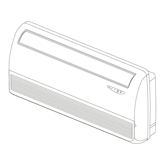
- Page 1 REMKO RKV 13 T / 24 T Wall/Ceiling Chests Operation Technology Spare Parts REMKO – powerful like a bear Edition GB – P05...
-
Page 3: Table Of Contents
Our guarantee becomes null and void if the unit is used, set up or maintained improperly, or if modifications are made to the supplied unit without our prior consent. Subject to alterations! Wall/Ceiling Chests REMKO RKV 13 T REMKO RKV 24 T Contents Contents Page... -
Page 4: Safety Hints
à Operate the units exclusively within the permissible The room air-conditioners in the REMKO RKV 13 T / operating ranges. 24 T series are split-design, direct-condensing units that Surrounding temperatures. -
Page 5: Operation
Operation 1 On / Off button Inserting the batteries into the remote control Press this button to put the unit into operation. The Prior to initial operation, the batteries supplied with the POWER display lights up. unit (2 type AAA batteries) must be inserted into the re- mote control. - Page 6 Button functionality The following commands can be performed using the remote control at a distance of no more than 7m. Point the remote control at the receiver on the right side of the wall-mounted unit. On / Off button Activate and deactivate the indoor unit with the ON / OFF button The following settings appear on display: COOL FAN AUTO = Fan speed...
- Page 7 Sleep button By pressing the SLEEP button, the room temperature increases by 1 °C one hour af- SLEEP ter the function has been activated. This function can be cancelled by pressing any button. The symbol disappears and the normal display appears. COOL / any button Functional process...
-
Page 8: Shutting Down The Unit
6. Closed the front of the unit. REMKO GmbH & Co. KG or your contract partner would be happy to provide you with the name of a service cen- tre in your area. -
Page 9: Troubleshooting
Should the unit still not work after performing these functional checks, please contact the closest dealer or REMKO GmbH & Co KG. directly. See also section “Customer Service and Guarantee“. -
Page 10: Technical Data
Technical Data Model RKV 13 T RKV 24 T Cooling capacity See corresponding outdoor part Refrigerant R 407C Operating range °C +15 °C to + 30 °C in 0.5 °C - steps Connection pressure line inch (mm) 3/8 (9.52) Connection intake line Inch (mm) 1/2 (12.7) -
Page 11: Assembly Instructions For Service Personnel
Assembly Instructions for Service Personnel Wall lead-throughs Important instructions prior to installation Wall lead-throughs are necessary to establish the con- à Ensure that the contents of the package are com- nection between the indoor unit and the outdoor part. plete and that the units have no visible damage re- Please observe the following: sulting from transport. -
Page 12: Installation
Installation Ceiling assembly When assembly the unit on the ceiling, the 4 integrated Assemble the indoor unit in such a way that con- ceiling mounts must be used. These are used to attach densation drainage is not blocked and air can al- the indoor unit by means of suitable dowels 8 mm ø;... -
Page 13: Impermeability Check
7. Before you flare the refrigerant lines, ensure that The connections that have been established are there is a swivel nut on the hose. Also make sure sprayed with a leak locator spray to test for imperme- that the flare has the correct shape. ability. -
Page 14: Condensation Connection
Electrical wiring diagram Indoor unit Outdoor unit Power supply External conductor A / R Neutral conductor White N / C 230 V~, 50 Hz, L1/N/PE Control conductor Orange 2 / Y To the compressor contactor Protective conductor Yellow-Green Connections to the outdoor units RKS and RKM The connection terminals of the outdoor units can have different labels depending on the type of unit: Indoor unit Description... -
Page 15: External Condensation Pump
External Condensation Pump Electrical connection of the condensation pump The electrical connections may only be made by author- The condensation pump which can be purchased as an ised service personnel in accordance with the relevant accessory (Ref. no. 1613167) transfers the condensa- regulations. -
Page 16: Prior To Initial Operation
Prior to Initial Operation The supplied ventilation hose must be used for the res- After the pressure has been tested, the vacuum pump ervoir to function properly. The end of the ventilation must be connected to the valve connections of the out- hose must at least be at the same height as the con- door part (see section “Impermeability Check”) by means densation tray to prevent water from overflowing. -
Page 17: Initial Operation
For the guarantee to be valid, the purchaser or his cus- due to the delayed start. tomer must completely fill out the "guarantee certificate" enclosed with all units and send it back to REMKO GmbH & Co. KG Test run procedure The units are repeatedly tested at the production site to ensure that they are working properly. -
Page 18: Certification Of Initial Operation
Certification for Initial operation Subsequent operation of a REMKO air-conditioning unit / system Unit data according to type plate Outdoor part Indoor unit 1 Indoor unit 2 Indoor unit 3 Unit type: Unit number: Setup location: Set up by: Name:... - Page 20 REMKO GmbH & Co. KG Klima- und Wärmetechnik D-32791 Lage Im Seelenkamp 12 • D-32777 Lage PO Box 1827 • Phone +49 (5232) 606 - 0 +49 (5232) 606260 E-Mail: info@remko.de Internet: www.remko.de...
Need help?
Do you have a question about the RKV 13 T and is the answer not in the manual?
Questions and answers