Table of Contents
Advertisement
Available languages
Available languages
Quick Links
Advertisement
Chapters
Table of Contents

Related Manuals for Speck pumpen BADU Jet Primavera


Summary of Contents for Speck pumpen BADU Jet Primavera
- Page 1 Originalbetriebsanleitung für Einbau-Gegenstrom-Schwimmanlage Hauptstraße 1-3 91233 Neunkirchen a. Sand Tel. 09123-949-0 Fax 09123-949-260 info@speck-pumps.com www.speck-pumps.com 01-2013 VG 766.2320.050...
-
Page 2: Table Of Contents
Inhaltsverzeichnis Inhaltsverzeichnis 1 Zu diesem Dokument ..............4 Umgang mit dieser Anleitung ........... 4 Mitgeltende Dokumente ............4 1.2.1 Symbole und Darstellungsmittel ........4 2 Sicherheit ..................6 Bestimmungsgemäße Verwendung ......... 6 2.1.1 Mögliche Fehlanwendungen .........6 Personalqualifikation ..............6 Sicherheitsvorschriften ............7 Schutzeinrichtungen .............. - Page 3 5.2.9 Elektrische Steuerung ..........21 Fertigmontage ............... 22 5.3.1 Pumpe aufstellen und an Rohrleitung anschließen ..29 Elektrischer Anschluss ............30 5.4.1 Elektrischer Anschluss für BADU Jet primavera ..30 5.4.2 Schaltplan 3~ 400/230V 50Hz ........31 5.4.3 Schaltplan 1~ 230V 50Hz ...........31 6 Inbetriebnahme ................32 Pumpe auf Leichtgängigkeit prüfen ........
-
Page 4: Zu Diesem Dokument
1 Zu diesem Dokument Zu diesem Dokument Umgang mit dieser Anleitung Diese Anleitung ist Teil der Gegenstrom-Schwimmanlage. Die Anlage wurde nach den anerkannten Regeln der Technik hergestellt und ge- prüft. Dennoch können bei unsachgemäßer Verwendung, bei unzu- reichender Wartung oder unzulässigen Eingriffen Gefahren für Leib und Leben bzw. - Page 5 1 Zu diesem Dokument Um die korrekte Bedienung zu verdeutlichen, sind wichtige Informatio- nen und technische Hinweise besonders herausgestellt. Symbol Bedeutung Einschrittige Handlungsaufforderung Mehrschrittige Handlungsanleitung Reihenfolge der Schritte beachten. 2010-101 VG 766.2320.050 DE 5...
-
Page 6: Sicherheit
2 Sicherheit Sicherheit Bestimmungsgemäße Verwendung Zum Einbau in alle Schwimmbecken-Ausführungen als Attraktion, zur Fitness, als Wellen- oder Luftperlbad, zur Unterwassermassage nach ärztlichen Rat, zum Schwimmen ohne Wende. Zur bestimmungsgemäßen Verwendung gehört die Beachtung folgen- der Informationen: Diese Anleitung Die Einbau-Gegenstrom-Schwimmanlage darf nur innerhalb der Ein- satzgrenzen betrieben werden. -
Page 7: Sicherheitsvorschriften
– Das Personal hat diese Anleitung gelesen und die erforderlichen Arbeitsschritte verstanden. Sicherheitsvorschriften Für die Einhaltung aller relevanten gesetzlichen Vorschriften und Richt- linien ist der Betreiber der BADU Jet primavera verantwortlich. Bei Verwendung der Anlage folgende Vorschriften beachten: – Warn- und Hinweisschilder am Produkt –... -
Page 8: Restrisiken
2 Sicherheit Restrisiken 2.7.1 Herabfallende Teile Nur geeignete und technisch einwandfreie Hebezeuge und Lastauf- nahmemittel verwenden. Nicht unter schwebenden Lasten aufhalten. 2.7.2 Rotierende Teile Scher- und Quetschgefahr besteht aufgrund von offenliegenden rotie- renden Teilen. Alle Arbeiten nur bei Stillstand der Pumpe durchführen. ... -
Page 9: Heiße Oberflächen
2 Sicherheit 2.7.4 Heiße Oberflächen Der Elektromotor kann eine Temperatur von bis zu 70 °C erreichen. Dadurch besteht Verbrennungsgefahr. Motor im Betrieb nicht berühren. Vor Arbeiten an der Pumpe Motor erst abkühlen lassen. 2.7.5 Ansauggefahr WARNUNG! Folgende Gefährdungen können sich ergeben: –... -
Page 10: Vermeidung Von Sachschäden
2 Sicherheit Vermeidung von Sachschäden 2.9.1 Undichtigkeit und Rohrleitungsbruch Nichteinhaltung der Aushärtezeit der ABS-Verklebungen kann zu Un- dichtigkeit und Überschwemmungen führen. Aushärtezeit der ABS-Verklebungen von mindestens 12h einhalten. Ausreichenden Bodenablauf vorsehen. Schwingungen und Wärmeausdehnung können Rohrleitungsbrüche verursachen. Anlage so installieren, dass Körper- und Luftschallübertragung ... -
Page 11: Überhitzen
2 Sicherheit 2.9.4 Überhitzen Folgende Faktoren können zu einer Überhitzung der Pumpe führen: Zu hoher Druck auf der Druckseite Falsch eingestellter Motorschutzschalter Zu hohe Umgebungstemperatur Pumpe nicht bei geschlossenen Armaturen betreiben. Motorschutzschalter installieren und korrekt einstellen. ... -
Page 12: Beschreibung
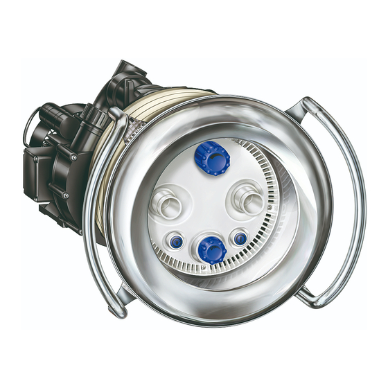
3 Beschreibung Beschreibung Komponenten (21/1) (54) (92) (111) (38/1) Einbaugehäuse (21/1) Mengenregulierung (92) Pumpe (38/1) Pneumatiktaster Pumpe (54) Düsen (38/2) Pneumatiktaster Licht (111) Luftregulierung Funktion Die Pumpe (92) ist über die Saug- und Druckleitung mit dem Kunststoff Einbaugehäuse (1) verbunden. Mit dem Pneumatiktaster (38/1) wird die Pumpe EIN/AUS geschaltet. -
Page 13: Transport Und Zwischenlagerung
4 Transport und Zwischenlagerung Transport und Zwischenlagerung Korrosion durch Lagerung in feuchter Luft bei wechselnden Temperatu- ren! Kondenswasser kann Wicklungen und Metallteile angreifen. Pumpe in trockener Umgebung bei möglichst konstanter Tempera- tur zwischenlagern. Beschädigung oder Verlust von Einzelteilen! Originalverpackung erst vor dem Einbau öffnen bzw. Einzelteile bis ... -
Page 14: Installation
5 Installation Installation Einbauort 5.1.1 Aufstellung im Freien Um die Lebensdauer der Pumpe zu erhöhen, einen einfachen Re- genschutz vorsehen. 5.1.2 Bodenablauf (muss vorhanden sein) Größe des Bodenablaufs nach folgenden Kriterien bemessen: – Größe des Schwimmbeckens – Umwälzvolumenstrom 5.1.3 Be- und Entlüftung Für ausreichende Be- und Entlüftung sorgen. -
Page 15: Aufstellung
5 Installation Aufstellung Einbauhinweis BADU Jet primavera: Haltegriff Folie Spannring Edelstahlblende Beton Einbaugehäuse Betonbecken mit Folie Dichtungen Ansaugblende Haltegriff Spannringe Fliesen Edelstahlblende Beton Einbaugehäuse Dichtung Betonbecken gefliest Ansaugblende Haltegriff Spannring Folie Edelstahlblende Beckenwand Einbaugehäuse Folienbecken Dichtungen Ansaugblende... -
Page 16: Montage Des Einbaugehäuses In Ein Betonbecken
5 Installation 5.2.1 Montage des Einbaugehäuses in ein Betonbecken Beachten Sie, dass der Druckanschluss oben über dem Sauganschluss angeordnet wird. Festlegung der Einbautiefe: Die Mitte des Einbauge- häuses / der Düsen soll sich 30cm unter dem Wasserspiegel befinden. Die Noppendichtung (26) im Gehäuse (1) einlegen, das Einbaugehäuse ausrichten und mit 4 Schneidschrauben an der Schalung befestigen. - Page 17 5 Installation Einbau an Schalung für Betonbecken Dicht-Rundschnur ! Druckanschluss OBEN ! Sauganschluss Schneidschraube Noppendichtung Schalung Schalung ~240 Abb.2 Montage des Einbaugehäuses in ein Betonbecken mit Folienauskleidung Bitte 5.2.3 beachten: Ausrichtung des Spannrings 34 106 Folie Abb.3 2010-101 VG 766.2320.050 DE 17...
-
Page 18: Montage Des Einbaugehäuses In Polyester-, Stahl- Oder Alubecken
5 Installation Montage des Einbaugehäuses in ein gefliestes Betonbecken Bitte 5.3.3 beachten: Ausrichtung des Spannrings 34 106 Abb.4 In einem gefliesten Becken wird die Fliesenstärke mit einem zusätzli- chen Spannring (28) und längeren Schneidschrauben (52) ausgegli- chen. Diese Teile sind im Zusatz-Kit optional erhältlich. 5.2.2 Montage des Einbaugehäuses in Polyester-, Stahl- oder Alubecken Beachten Sie, dass der Druckanschluss oben über dem Sauganschluss... - Page 19 5 Installation Beckenausschnitt für Polyesterbecken/ Folienbecken Ø7 1) Befestigung Spannring (12x) Abb.5 Montage des Einbaugehäuses in ein Polyesterbecken Bitte 5.2.3 beachten: Ausrichtung des Spannrings 34 106 Polyesterbecken Abb.6 2010-101 VG 766.2320.050 DE 19...
-
Page 20: Ausrichtung Des Spannrings
5 Installation Montage des Einbaugehäuses in ein Folienbecken Bitte 5.2.3 beachten: Ausrichtung des Spannrings 34 106 Folienbecken Abb. 7 5.2.3 Ausrichtung des Spannrings Die vier mit (1) markierten Bohrungen müssen immer im 45° Winkel zur Mittelachse stehen. 5.2.4 Schutzschlauch und Schlauch für Luftregulierung Schutzschlauch und Schlauch für Luftregulierung über den Wasser- spiegel führen und befestigen. -
Page 21: Rohrleitung Dimensionieren
5 Installation 5.2.5 Rohrleitung dimensionieren Zu lange Saugleitungen haben erhebliche Nachteile: Höherer Widerstand, dadurch schlechteres Ansaugverhalten und höhere Kavitionsgefahr Längere Ansaugzeit (bis zu 12 min). ACHTUNG! Das Einbaugehäuse und die Verschraubungen sind aus ABS. Eine Aushärtezeit der Verklebung von mindestens 12 Stunden muss berücksichtigt werden! 5.2.6 Rohrleitung verlegen... -
Page 22: Fertigmontage
5 Installation Fertigmontage Nach dem Einbau des Einbaugehäuses (Vormontagesatz): 1. Einkleben des Kabelschutzschlauches und des äußeren Luftlei- tungsschlauches (Abb. 9). 2. O-Ring (108) in das Einbaugehäuse (1) einlegen (Abb. 10). 3. Die zehn beigelegten Schneidschrauben (61) in Düsengehäuse einschrauben. Vormontiertes Düsengehäuse (102.1) am Einbau- gehäuse (1) ansetzen (Abb. - Page 23 5 Installation 9. Edelstahlblende (93.1) mit den vorstehenden Zentriernoppen auf den vorhandenen Aussparungen der Ansaugblende (93) ausrich- ten und von Hand aneinanderpressen. Markierung "OBEN" auf der Edelstahlblende beachten. Zur Arretierung der Blende die zwei seitlichen Biegelaschen mit einem Schraubendreher nach hinten umbiegen (Abb.11).
- Page 24 5 Installation Druckanschluss Reserve Kabelschutzschlauch ø25 Sauganschluss Abb.9 Luftleitungsschlauch ø20 102.1 Abb.10 24 DE VG 766.2320.050 2010-101...
- Page 25 5 Installation 93.1 Demontage: Montage: Mit spitzen Schrau- Mit Schrauben- bendreher Lasche dreher Lasche nach vorne zurück- nach hinten biegen! (2x) umbiegen! (2x) Abb.11 2010-101 VG 766.2320.050 DE 25...
- Page 26 5 Installation 38/1 38/2 Abb.12 26 DE VG 766.2320.050 2010-101...
- Page 27 5 Installation 21/1 Abb.13 100/1 106.1 105.1 Abb.14 2010-101 VG 766.2320.050 DE 27...
- Page 28 5 Installation DRUCK Klebeanschluss SAUG Klebeanschluss Abb.15 28 DE VG 766.2320.050 2010-101...
-
Page 29: Pumpe Aufstellen Und An Rohrleitung Anschließen
5 Installation Be- und Entlüftung DN 150 (125) (min. 11) Maße in cm Schachtbreite min. 70 cm Schaltanlage im trockenen Raum und über dem Wasserspiegel montieren. Schlauch für Luftregulierung DN 90 und Pneumatiktaster über den Wasserspiegel führen Erdungsband und befestigen Be- und Entlüftung zur Vermeidung von Kondenswasser Ausreichend dimensionierter Ablauf erforderlich... -
Page 30: Elektrischer Anschluss
Schalter gem. DIN EN 809 vorsehen. Entsprechend dieser Norm muss das der Errichter/Betreiber entscheiden. 5.4.1 Elektrischer Anschluss für BADU Jet primavera Die Schaltung ist anschlussfertig verdrahtet, die Anschlüsse werden nach Schaltplan vorgenommen. Pneumatikschläuche der Pneumatiktaster mit Schaltkasten verbin- ... -
Page 31: Schaltplan 3~ 400/230V 50Hz
5 Installation 5.4.2 Schaltplan 3~ 400/230V 50Hz Bauseitiger Anschluss Drehrichtung rechts. Pumpe wird bei 400V 3 N AC 50 Hz im betrieben (Auslieferungszustand) Pumpe wird bei 230V 3 N AC 50 Hz im betrieben 5.4.3 Schaltplan 1~ 230V 50Hz Bauseitiger Anschluss 2010-101 VG 766.2320.050 DE 31... -
Page 32: Inbetriebnahme
6 Inbetriebnahme Inbetriebnahme Beschädigung der Pumpe durch Trockenlauf! Sicherstellen, dass Pumpe immer mit Wasser gefüllt ist. Dies gilt auch für die Drehrichtungskontrolle. Pumpe auf Leichtgängigkeit prüfen Nach längerer Stillstandzeit muss die Pumpe im ausgeschalteten und spannungsfreien Zustand auf Leichtgängigkeit geprüft werden. Schraubendreher in den Schlitz am Motorwellenende (Lüfterseite) ... -
Page 33: Betrieb
7 Betrieb Betrieb Das Ein- und Ausschalten der Anlage wird durch Druck auf den unter dem Wasserspiegel in der Blende eingebauten Pneumatik- taster vorgenommen, d. h. keine elektrische Betätigungseinheit im Becken. Mit der Mengenregulierung, welche über den Düsen eingebaut ist, kann die Leistung reguliert werden. -
Page 34: Störungen
8 Störungen Störungen Es ist normal, dass von Zeit zu Zeit einige Tropfen Wasser durch die Gleitringdichtung austreten. Das gilt insbesondere während der Ein- laufzeit. Je nach Wasserbeschaffenheit und Betriebsstundenzahl kann die Gleitringdichtung undicht werden. Bei permanentem Wasseraustritt Gleitringdichtung wechseln. ... -
Page 35: Pumpe Nach Ansprechen Eines Schutzkontakts/-Schalters Prüfen
8 Störungen 8.1.1 Pumpe nach Ansprechen eines Schutzkontakts/-schalters prüfen Wurde der Motor durch den Wicklungsschutzkontakt oder den Motor- schutzschalter ausgeschaltet, folgende Schritte durchführen: 1. Anlage von der Spannungsversorgung trennen. 2. Motorwelle lüfterseitig mit einem Schraubendreher durchdrehen und auf Leichtgängigkeit prüfen. Motorwelle schwergängig: 1. -
Page 36: Instandhaltung
Nach Beendigung der Instandhaltungsarbeiten alle erforderlichen Maßnahmen für die Inbetriebnahme ergreifen. Die Blende und der Haltegriff der BADU Jet primavera sind aus Edel- stahl. Aufgrund von verschiedenen Wasserinhaltsstoffen müssen die Teile von Zeit zu Zeit gereinigt werden um möglichen Korrosionsschä- den vorzubeugen. -
Page 37: Austausch Des Led-Scheinwerfers
9 Instandhaltung Austausch des LED-Scheinwerfers 2010-101 VG 766.2320.050 DE 37... - Page 38 9 Instandhaltung Einsetzen des neuen LED-Scheinwerfers und Zusammenbau der Anla- ge in umgekehrter Reihenfolge. Montage der Luftregulierung siehe S.26 Abb.12! 38 DE VG 766.2320.050 2010-101...
-
Page 39: Technische Daten
10 Technische Daten Technische Daten Technische Daten bei 50 Hz BADU Jet primavera Jet Pumpe 21-81/33 G 29° Förderstrom der Pumpe (m /h) 3 N~ 400/230 V Spannung 1~ 230 V Leistungsaufnahme P (kW) 3~/1~ 3,80 / 3,90 Leistungsabgabe P (kW) - Page 40 Original operation manual for Submerged counter-current pool unit Hauptstraße 1-3 91233 Neunkirchen a. Sand Tel. +49 (0)9123-949-0 Fax +49 (0)9123-949-260 info@speck-pumps.com www.speck-pumps.com 01-2013 VG 766.2320.050...
- Page 41 Table of contents Table of contents 1 About this document ..............4 Using this manual ..............4 Other applicable documents ............ 4 1.2.1 Symbols and means of representation ......4 2 Safety ....................6 Intended use ................6 2.1.1 Possible misuse ............6 Personnel qualification .............
- Page 42 5.3.1 Installing the pump and connecting it to the pipe ..29 Electrical connection .............. 30 5.4.1 Electrical connection for BADU Jet primavera ....30 5.4.2 Wiring diagram 3-phase 400/230 V 50 Hz ....31 5.4.3 Wiring diagram 1-phase 230 V 50 Hz ......31 6 Start-up ..................
-
Page 43: About This Document
1 About this document About this document Using this manual This manual is a component of the counter-current pool unit. The sys- tem was manufactured and tested according to the generally accepted rules of technology. However, if the pump is used incorrectly, not ser- viced enough or tampered with, danger to life and limb or material damage could result. - Page 44 To explain correct operation, important information and technical notes are specially marked. Symbol Meaning Instructions for a one-step action Directions for a multi-step action Observe the order of the steps. 2013-01 VG 766.2320.050 EN 5...
-
Page 45: Safety
2 Safety Safety Intended use For installation in all swimming pool versions as a talking point, for fitness training, as a wave or air bubble bath, underwater massage after medical consultation, for endless no-lap swimming. Observing the following information is vital for intended use: ... -
Page 46: Safety Regulations
– The personnel has read this manual and understood the neces- sary working steps. Safety regulations The operator of the BADU Jet primavera is responsible for the adher- ence to all relevant statutory regulations and guidelines. Observe the following regulations when using the system: ... -
Page 47: Residual Risk
2 Safety Residual risk 2.7.1 Falling parts Use only hoisting and load-bearing equipment which is suitable and technically sound. Do not stand under suspended loads. 2.7.2 Rotating parts There is a risk of shearing and crushing due to exposed rotating parts. Perform service only when the pump is not in operation. -
Page 48: Hot Surfaces
2 Safety 2.7.4 Hot surfaces The electric motor can reach temperatures of up to 70 °C. There is a risk of being burned. Do not touch the motor during operation. Allow the pump to cool down before servicing it. ... -
Page 49: Preventing Material Damage
2 Safety Preventing material damage 2.9.1 Leakage and pipe breakage Non-observance of the curing time of the ABS bonding time can result in leaks and flooding. Observe the curing time for the ABS bonding of at least 12 h. Provide sufficient ground drain. -
Page 50: Overheating
2 Safety 2.9.4 Overheating The following factors can result in the pump overheating: Excessive pressure on the delivery side Motor overload switch set incorrectly Ambient temperature which is too high Do not operate the pump with the valves closed. ... -
Page 51: Description
3 Description Description Components (21/1) (54) (92) (111) (38/1) Main housing (21/1) Volume regulator (92) Pump (38/1) Pneumatic button pump (54) Nozzles (38/2) Pneumatic button light (111) Air regulator Function The pump (92) is connected via the suction and pressure line with the plastic main housing (1). -
Page 52: Transport And Intermediate Storage
4 Transport and intermediate storage Transport and intermediate storage Corrosion is possible due to being stored in humid air and fluctuating temperatures! Condensation can corrode windings and metal parts. Store the pump in a dry environment at a temperature which is as ... -
Page 53: Installation
5 Installation Installation Installation site 5.1.1 Outdoor installation In order to increase the pump's service life, provide simple weather protection. 5.1.2 Ground drain (has to exist) Area around the equipment should have appropriate drainage: – Size of the swimming pool –... -
Page 54: Installation
5 Installation Installation Installation instructions BADU Jet primavera: Handle vinyl Support ring Stainless steel panel Concrete Main housing Concrete pool with vinyl Seals Suction panel Handle Support rings Tiles Stainless steel panel Concrete Main housing Seal Suction panel Concrete pool tiled ... -
Page 55: Mounting Of The Main Housing In A Concrete Pool
5 Installation 5.2.1 Mounting of the main housing in a concrete pool Ensure that the outlet connection top is positioned above the inlet con- nection. Specification of the mounting depth: The middle of the main housing / nozzles should lie 30 cm under the water level. Insert the nub seal (26) in the housing (1), align the main housing and fasten with 4 tapping screws to the formwork. - Page 56 5 Installation Installation of formwork for concrete pool Sealing round cord ! Outlet connection UP ! Inlet connection Tapping screw Nub seal Formwork Formwork ~240 Fig. 2 Mounting of the main housing in a concrete pool with vinyl lining Please observe 5.2.3: Aligning the support ring 34 106 Foil Fig.
-
Page 57: Mounting Of The Main Housing In A Polyester, Steel Or Aluminium Pool
5 Installation Mounting of the main housing in a tiled concrete pool Please observe 5.3.3: Aligning the support ring 34 106 Fig. 4 In a tiled pool the tile thickness is compensated with an additional sup- port ring (28) and longer tapping screws (52). The parts are available as an option in the additional kit. - Page 58 5 Installation Pool cut-out for polyester pool/ liner pool Ø7 1) Fastening support ring (12x) Fig. 5 Mounting of the main housing in a polyester pool Please observe 5.2.3: Aligning the support ring 34 106 Polyester pool Fig. 6 2013-01 VG 766.2320.050 EN 19...
-
Page 59: Aligning The Support Ring
5 Installation Mounting of the main housing in a liner pool Please observe 5.2.3: Aligning the support ring 34 106 Liner pool Fig. 7 5.2.3 Aligning the support ring The four holes marked with (1) must always be positioned at a 45° angle to the centre axis. -
Page 60: Pipe Sizing
5 Installation 5.2.5 Pipe sizing Suction lines which are too long have significant disadvantages: Higher resistance which results in less flow and a higher risk of cavitation Longer priming time (up to 12 min). ATTENTION! The main housing and the screw connections are made of ABS. -
Page 61: Final Assembly
5 Installation Final assembly After the installation of the main housing (pre-assembly kit): 1. Bonding in of the cable protective conduit and of the outer air hose (Fig. 9). 2. Insert the O-ring (108) in the main housing (1) (Fig. 10). 3. - Page 62 5 Installation 9. Align the stainless-steel cover (93.1) with the projecting centring nubs to the existing recesses of the suction panel (93). Observe the "UP" marking on the stainless-steel cover. To fasten the cover use a screwdriver to bend the two offset tabs towards the back (Fig. 11). 10.
- Page 63 5 Installation Outlet connection Reserve Cable protection hose ø25 Inlet connection Fig. 9 Air hose ø20 102.1 Fig. 10 24 EN VG 766.2320.050 2013-01...
- Page 64 5 Installation 93.1 Disassembling: Mounting: Use a flat-blade Use a screw- screwdriver to bend driver to bend the lash forwards the tab to the again! (2x) rear! (2x) Fig. 11 2013-01 VG 766.2320.050 EN 25...
- Page 65 5 Installation 38/1 38/2 Fig. 12 26 EN VG 766.2320.050 2013-01...
- Page 66 5 Installation 21/1 Fig. 13 100/1 106.1 105.1 Fig. 14 2013-01 VG 766.2320.050 EN 27...
- Page 67 5 Installation PRESSURE Glue connection SUCTION Glue connection Fig. 15 28 EN VG 766.2320.050 2013-01...
-
Page 68: Installing The Pump And Connecting It To The Pipe
5 Installation Ventilation and exhaust DN 150 (125) (min. 11) Dimensions in cm Shaft width min. 70 cm Mount switchgear in dry room and above the water level Lay and fasten the hose DN 90 for the air regulation and pneumatic button above Earthing strap the water level... -
Page 69: Electrical Connection
DIN EN 809. The builder/operator must make a deci- sion according to this standard. 5.4.1 Electrical connection for BADU Jet primavera The circuiting is wired ready for connection. The connections are carried out in accordance with the wiring diagram. -
Page 70: Wiring Diagram 3-Phase 400/230 V 50 Hz
5.4.2 Wiring diagram 3-phase 400/230 V 50 Hz Control box Pump SELV Connection - option for Power: 400V 3N AC 50HZ remote control (potential-free contacts) Connection by customer Pump Fusing at customer Direction of rotation clockwise PUMP Pump is operated at 400V 3 N AC 50 Hz in m to DIN VDE 0100-702 (state of delivery) Pump is operated at 230V 3 N AC 50 Hz in m... -
Page 71: Start-Up
6 Start-up Start-up The pump can be damaged if it runs dry! Ensure that the pump is full of water. This also applies to checking the rotation direction. Checking how easily the pump rotates After longer idle periods, the pump must be check for how easily it rotates while it is switched off. -
Page 72: Operation
7 Operation Operation The system is switched on and off by pressing the pneumatic button built into the cover under the water level. Meaning that there is no electrical operating unit in the pool. The output can be controlled by using the volume regulator that is installed above the nozzles. -
Page 73: Defects
8 Defects Defects It is normal for a few drops of water to escape from the mechanical seal from time to time. This is especially true during the break-in period. Depending on the water quality and number of operating hours, the mechanical seal can begin to leak. -
Page 74: Checking The Pump After The Overload Switch Has Tripped
8.1.1 Checking the pump after the overload switch has tripped If the motor has been switched off by the built-in overload switch or the motor overload switch, carry out the following steps: 1. Disconnect system from the power supply. 2. Turn the motor shaft on the fan side using a screw driver and check if it turns easily. -
Page 75: Maintenance
After completing all maintenance work, perform all necessary measures for start-up. The cover and the handle of the BADU Jet primavera are made of stainless steel. Due to the various water components the parts have to be cleaned periodically to avoid possible corrosive damage. -
Page 76: Replacing The Led Floodlight
9 Maintenance Replacing the LED floodlight 2013-01 VG 766.2320.050 EN 37... - Page 77 9 Maintenance Insertion of the new LED spotlight and assembly of the system in the reverse order. Mounting the air regulator, see P. 26, Fig. 12! 38 EN VG 766.2320.050 2013-01...
-
Page 78: Technical Data
10 Technical data Technical data Technical data at 50 Hz BADU Jet primavera Jet pump 21-81/33 G 29° Flow rate of the pump (m 3-phase 3 N-phase 400/230 V Voltage 1-phase 1-phase 230 V Power input P (kW) 3-phase/1-phase 3.80 / 3.90...
Need help?
Do you have a question about the BADU Jet Primavera and is the answer not in the manual?
Questions and answers