
Subscribe to Our Youtube Channel
Related Manuals for Woodward MRI3-ITE


Summary of Contents for Woodward MRI3-ITE
- Page 1 MRI3-ITE(R) – Time overcurrent relay with thermal replica and earth current measuring Manual MRI3-ITER (Revision A)
- Page 2 Woodward Manual MRI3-ITER GB Woodward Governor Company reserves the right to update any portion of this publication at any time. Information provided by Woodward Governor Company is believed to be correct and reliable. However, no responsibility is as- sumed by Woodward Governor Company unless otherwise expressly undertaken.
-
Page 3: Table Of Contents
Manual MRI3-ITER GB Woodward Contents Introduction and Application ..............5 Features and characteristics ..............6 Design ......................7 Connections ........................7 3.1.1 Analogue input circuits ....................8 3.1.2 Output relays ........................9 ... - Page 4 Secondary injection test ....................40 6.4.1 Test equipment ......................40 6.4.2 Example of test circuit for MRI3-ITE ................41 6.4.3 Checking the input circuits and measured values ............41 6.4.4 Example of a test circuit with earth fault directional feature ......... 42 ...
-
Page 5: Introduction And Application
Woodward 1. Introduction and Application The digital multifunctional relay MRI3-ITE(R) has been designed as a universal time over current protection relay with thermal replica for generators, transformers and cables. The relay gives a complete thermal characteristic of the electrical equipment to be protected taking into account its initial load. -
Page 6: Features And Characteristics
Woodward Manual MRI3-ITER GB 2. Features and characteristics Microprocessor technology with self-supervision, measuring of phase current as RMS value, digital filtering of the measured values by using discrete Fourier analysis to suppress the high frequence harmonics and DC components induced by faults or system operations (earth current only), ... -
Page 7: Design
Manual MRI3-ITER GB Woodward 3. Design Connections Figure 3.1: Connection diagram Figure 3.2: Phase current measuring and earth-current detection by means of Holmgreen-circuit. This connection can be used with three existing phase current transformers when combined phase and earth-current measuring is required. -
Page 8: Analogue Input Circuits
Woodward Manual MRI3-ITER GB Figure 3.3: Earth-fault measuring by means of ring-core C.T. (IE) When phase- and earth-fault current measuring are combined, the connection has to be realized as per Figure 3.2 and Figure 3.3. Voltage measuring for the directional detection: Figure 3.4: Measuring of the phase voltages for the directional detection at earth-fault protection (IE>... -
Page 9: Output Relays
Manual MRI3-ITER GB Woodward 3.1.2 Output relays Two relays are equipped with two change-over contacts and three relays with each one change- over contact for alarm. Apart from the relay for self-supervision, all protective functions can be op- tionally assigned: ... -
Page 10: Blocking Input
Woodward Manual MRI3-ITER GB 3.2.1 Blocking input The function for blocking can be parameterized arbitrary. When an auxiliary voltage is connected to D8/E8 those relay functions will be blocked which were parameterized before (see chapter 5.7.1). 3.2.2 External reset input See chapter 5.9... - Page 11 Manual MRI3-ITER GB Woodward Figure 3.7: Basic set-up of the fault recorder Each memory segment has a specified storage time which permits setting of a time prior to the trigger event. Via the interface RS485 the data can be read and processed by means of a PC with HTL/PL-Soft4.
-
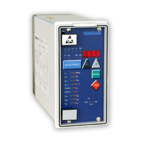
Page 12: Front Plate
Woodward Manual MRI3-ITER GB Front plate Figure 3.8: Front plate MRI3-ITE Figure 3.9: Front plate MRI3-ITER DOK-TD-MRI3 ITERE Rev.A... - Page 13 Woodward The LED RS, and yellow light up yellow (MRI3-ITE) The LED RS, IP and IQ light up yellow (MRI3-ITER). All other LEDs are two-colored. LEDs left to the alphanumerical display light-up green during mea- suring and red at alarm.
-
Page 14: Working Principle
Digital circuits The essential part of the MRI3-ITE relay is a powerful microcontroller. All of the operations, from the analogue digital conversion to the relay trip decision, are carried out by the microcontroller digi- tally. The relay program is located in an EPROM (Electrically-Programmable-Read-Only-Memory). -
Page 15: Thermal Replica
Constant to be multiplied by the basic current in order to determine the current that may be higher than I Instruction for motor protection: k = 1...1.2 MRI3-ITE(R) default value: k = 0.5 Remark: For the calculation of the temperature equivalent, only the basic current has to be taken into ac- ~ . -
Page 16: Algorithm
(e.g. ohmic losses and iron losses in the transformer). Q I² or I² Since the pickup value in the MRI3-ITE is deter-mined by I , the following relation is effective: n k² (I k)²... - Page 17 Manual MRI3-ITER GB Woodward The thermal equivalent ( T = ) is described by an exponential function. for (> (t‘)= 0+( - ) (1- after transposition: (t)= - +( )· ·100% the alarm or trip element is activated.
- Page 18 Woodward Manual MRI3-ITER GB The temperature equivalent has not been calculated after start of the protection program (con- nection of auxiliary voltage), therefore, the temperature state of the electrical item to be protected is expected to be cold. If, however, the electrical equipment has been initially loaded, it will take approximately 3 x ...
-
Page 19: Earth Fault Protection
Manual MRI3-ITER GB Woodward Earth fault protection 4.5.1 Generator stator earth fault protection With the generator neutral point earthed as shown in Figure 4.4 the MRI3-ITER picks up only to phase earth faults between the generator and the location of the current transformers supplying the relay. -
Page 20: Earth-Fault Directional Feature (Er-Relay Type)
Woodward Manual MRI3-ITER GB Earth-fault directional feature (ER-relay type) A built-in earth-fault directional element is available for applications to power networks with isolated or with arc suppressing coil compensated neutral point. For earth-fault direction detection it is mainly the question to evaluate the power flow direction in zero sequence system. - Page 21 Manual MRI3-ITER GB Woodward Figure 4.6: Phase position between the residual voltage and zero sequence current for faulted and non-faulted lines in case of isolated systems (sin - residual voltage - zero sequence current - capacitive component of zero sequence current - resistive component of zero sequence current By calculating the reactive current component (sin ...
-
Page 22: Demand Imposed On The Main Current Transformers
Woodward Manual MRI3-ITER GB In compensated mains the earthfault direction cannot be determined from the reactive current components because the reactive part of the earth current depends upon the compensation level of the mains. The ohmic component of the total cur-rent (calculated by cos adjustment) is used in order to determine the direction. -
Page 23: Operation And Settings
Manual MRI3-ITER GB Woodward 5. Operation and settings Display Function Display shows Pressed pushbutton Corresponding Normal operation Measured operating values actual measured val- <SELECT/RESET> L1, L2, L3, E ues, related to I one time for each value , ... - Page 24 Woodward Manual MRI3-ITER GB Function Display shows Pressed pushbutton Corresponding IE>> Save parameter? SAV? <ENTER> Save parameter! SAV! <ENTER> for about 3 s Display of software-version First part (e.g. D21-) <TRIP> Second part (e.g. 1.00) one time for each part Setting of the transformer connec- 1:1;...
-
Page 25: Leds
Warning at k yellow/MRI3-ITE continuously Temperature limit of overload low 100% green/MRI3-ITER set element reached Tripping at k · yellow / MRI3-ITE continuously Temperature limit of trip element 100% / MRI3-ITER reached Warning at k · green continuously... - Page 26 Setting time delay t IE>> IE>> Pickup flashing Pickup of I E>> IE>> E>> Tripping continuously , tripped E>> IE>> E>> Setting yellow continuously Setting slave address Table 5.2: LED-indication * MRI3-ITER type only **only MRI3-ITE type DOK-TD-MRI3 ITERE Rev.A...
-
Page 27: Setting Procedure
Manual MRI3-ITER GB Woodward Setting procedure After push button <SELECT/RESET> has been pressed, always the next measuring value is indi- cated. Firstly the operating measuring values are indicated and then the setting parameters. By pressing the <ENTER> push button the setting values can directly be called up and changed. -
Page 28: Nominal Frequency
Woodward Manual MRI3-ITER GB 5.3.5 Nominal frequency The adapted FFT-algorithm requires the nominal frequency as a parameter for correct digital sampling and filtering of the input currents. By pressing <SELECT> the display shows "f=50" or "f=60". The desired nominal frequency can be adjusted by <+>... -
Page 29: Protection Parameters
Manual MRI3-ITER GB Woodward Protection parameters 5.4.1 Pickup value of the thermal overload protection I and I For basic current I , the max. permissible operating current or optionally the rated current of the ob- ject to be protected has to be used in either case based on rated secondary quantities. 100% of the thermal equivalent ... -
Page 30: Time Current Characteristics For Phase Overcurrent Element (Char I>)
Woodward Manual MRI3-ITER GB 5.4.6 Time current characteristics for phase overcurrent element (CHAR I>) By setting this parameter, one of the following 6 messages appears on the display: DEFT - Definite time Normal inverse NINV Very inverse VINV Extremely inverse... -
Page 31: Pickup Value For Residual Voltage U (Iter-Relay Type)
Manual MRI3-ITER GB Woodward 5.4.11 Pickup value for residual voltage U (ITER-relay type) Regardless of the preset earth current, an earth fault is only identified if the residual voltage ex- ceeds the set reference value. This value is indicated in volt. -
Page 32: Trip Delay For High Set Element Of Earth Fault Supervision (T Cos/Sin Measurement (Er - Relay Type)
Woodward Manual MRI3-ITER GB 5.4.18 Trip delay for high set element of earth fault supervision (t IE>> (Similar to 5.4.10) 5.4.19 COS/SIN Measurement (ER - relay type) Depending on the neutral earthing connection of the protected system the directional element of the earth fault relay must be preset to cos ... -
Page 33: Fault Recorder
Woodward Fault recorder 5.5.1 Adjustment of the fault recorder The MRI3-ITE is equipped with a fault recorder (see chapter 3.2.3). Three parameters can be de- termined. 5.5.2 Number of the fault recordings The max. recording time is 16 s at 50 Hz or 13.33 s at 60 Hz. -
Page 34: Additional Functions
5.7.1 Blocking of the protective functions Blocking of the protective functions: The MRI3-ITE(R) is equipped with a blocking function that can be parameterized arbitrary. Con- necting supply voltage to terminals D8/E8 blocking of those functions which were selected by the user takes place. - Page 35 Assignment to the output relays: Unit MRI3-ITE has five output relays. The fifth out-put relay is provided as permanent alarm relay for self supervision is normally on. Output relays 1 - 4 are normally off and can be assigned as alarm or tripping relays to the frequency functions which can either be done by using the pushbut- tons on the front plate or via serial interface RS485.
- Page 36 Woodward Manual MRI3-ITER GB Relay function Output relays Display- Corresponding indication Alarm _ 2 _ _ I>: green Trip 1 _ _ _ : red I> Alarm _ 2 _ _ I>: green Trip 1 _ _ _ : red I>...
-
Page 37: Indication Of Measuring And Fault Values
Apparent Current in phase 2 (LED L2 green) Apparent Current in phase 3 (LED L3 green) Temperature equivalent A> in % (LED A yellow), (for MRI3-ITE) Temperature equivalent > in % (LED T red), (for MRI3-ITE) ... -
Page 38: Indication Of Fault Data
Woodward Manual MRI3-ITER GB Earth voltage Indication as Range Unit Sec. voltage 000V – 999V Primary voltage .000 – 999 1K00 – 9K99 10K0 – 99K0 100K – 999K 1M00 – 9M99 5.8.3 Indication of fault data All faults detected by the relay are indicated on the front plate optically. For this purpose, the four LEDs (L1, L2, L3, E) and the four function LEDs (I>, I>>, IE>, IE>>... -
Page 39: Reset
Manual MRI3-ITER GB Woodward Reset Unit MRI3-ITER has the following three possibilities to reset the display of the unit as well as the output relay at jumper position J3=ON. Manual Reset Pressing the pushbutton <SELECT/RESET> for some time (about 3 s) Electrical Reset ... -
Page 40: Relay Testing And Commissioning
Woodward Manual MRI3-ITER GB 6. Relay testing and commissioning The test instructions following below help to verify the protection relay performance before or dur- ing commissioning of the protection system. To avoid a relay damage and to ensure a correct relay operation, be sure that: ... -
Page 41: Example Of Test Circuit For Mri3-Ite
Woodward 6.4.2 Example of test circuit for MRI3-ITE For testing MRI3-ITE relays only current input signals are required. Figure 6.1 shows a simple ex- ample of a single phase test circuit with adjustable current energizing the MRI3-ITE relay under test. -
Page 42: Example Of A Test Circuit With Earth Fault Directional Feature
Woodward Manual MRI3-ITER GB 6.4.4 Example of a test circuit with earth fault directional feature Figure 6.2: Test circuit For testing MRI3-ITER relays with earth fault directional feature, current and voltage sources are required, with one of the two sources having to be equipped with a phase shifter. -
Page 43: Checking The Operating And Resetting Values Of The Relay
Manual MRI3-ITER GB Woodward 6.4.5 Checking the operating and resetting values of the relay Inject a current which is less than the relay set values in phase 1 of the relay and gradually in- crease the current until the relay starts, i.e. at the moment when the LED I> and L1 light up or the alarm out-put relay I>... -
Page 44: Testing The External Blocking With Block/Trip Function
Woodward Manual MRI3-ITER GB 6.4.9 Testing the external blocking with Block/Trip function In order to simplify things, the short-circuit stage is to be tested here as described in Chapter 6.4.7. For this purpose, the parameter for the Block/Trip function must be set to "TR_B" (first value in the blocking menu of the protection functions Chapter 5.7.1). -
Page 45: Maintenance
Manual MRI3-ITER GB Woodward Maintenance Maintenance testing is generally done on site at regular intervals. These intervals vary among us- ers depending on many factors: e.g. the type of protective relays employed; the importance of the primary equipment being protected; the user's past experience with the relay, etc. -
Page 46: Technical Data
Woodward Manual MRI3-ITER GB 7. Technical data Measuring circuits Rated data: Nominal current I 1 A or 5 A Nominal frequency f 50/60 Hz adjustable Power consumption in current circuit: at I = 1 A 0.2 VA at I = 5 A 0.1 VA... -
Page 47: Setting Ranges And Steps
Manual MRI3-ITER GB Woodward Setting ranges and steps 7.3.1 Systemparameter Setting range Step Tolerance Iprim (SEK) 0.002... 50.0 kA 0.001 kA (0.002...0.200) L1 L2 L3 E 0.002 kA (0.200...0.500) 0.005 kA (0.500...1.00) 0.01 kA (1.00...2.00) 0.02 kA (2.00...5.00) 0.05 kA (5.00...10.0) -
Page 48: Overload Protection
Woodward Manual MRI3-ITER GB 7.3.2 Overload protection Setting range Step Tolerance 0.4...3.5 x I (EXIT) 0.02 x I (0.4...1.0) 3% from set value B,Alarm 0.05 x I (1.0...3.5) or 2.5% I 0.5...5 0.01 (0.5...1.0) 0.02 (1.0...2.0) 0.05 (2.0...5.0) 0.04 - 260 s (EXIT) 0.02... -
Page 49: Over Current Time Protection
Manual MRI3-ITER GB Woodward 7.3.3 Over current time protection Setting range Step Tolerance 3% from set value I> 0.2...4.0 x I (EXIT) 0.01 (0.2...0.5) 0.02 (0.5...1.0) 0.05 (1.0...2.0) (2.0...4.0) 3% or 20 ms 0.04 - 260 s (EXIT) 0.02 (0.04...1.0) I>... -
Page 50: Earth Fault Protection
Woodward Manual MRI3-ITER GB 7.3.4 Earth fault protection Setting range Step Tolerance 0.01...2.0 x I (EXIT) (E) 0.001 (0.01...0.05) 3% from set value E> 0.01...0.45 x I (EXIT) 0.002 (0.05...0.1) or 0.3% I (ER) 0.005 (0.1...0.2) 0.01 (0.2...0.5) 0.02 (0.5...1.0) 0.05... -
Page 51: Determination Of Earth Fault Direction (Mrl3-Iter)
(1)* 2 x 6.66 s, (3)* 4 x 3.33 s, (7)* 8 x 1.66 s (60 Hz) Saving of the recording at the P_UP; TRIP; A_PI; TEST occurrence Pre-trigger-time 0.05 s – 8.00 s * is written over when a new trigger signal arrives ** only MRI3-ITE DOK-TD-MRI3 ITERE Rev.A... -
Page 52: Tripping Characteristics
Woodward Manual MRI3-ITER GB Tripping characteristics 7.4.1 Thermal characteristic From the equation for the temperature equivalent: t / · 100% · 100% · k · I k · I it is possible to deduce the tripping characteristics according to IEC 155-8. -
Page 53: Preload Factor
Manual MRI3-ITER GB Woodward 7.4.2 Preload factor The normal tripping characteristic according to IEC 255-8: · In Figure 7.1: Tripping characteristics for various preload factors p and constant k=1,0. DOK-TD-MRI3 ITERE Rev.A... -
Page 54: Inverse Time Over Current Protection Relay
Woodward Manual MRI3-ITER GB 7.4.3 Inverse time over current protection relay According to IEC 255-4 or BS 142 Normal Inverse (type A) 0.14 · Very Inverse (type B) 13.5 · Extremely Inverse (type C) · Long time inverse · RI-inverse ·... -
Page 55: Tripping Characteristics
Manual MRI3-ITER GB Woodward Tripping characteristics 1000 I> 10.0 t[s] 0.05 5 6 7 8 910 Figure 7.2: Normal Inverse 1000 I> t[s] 10.0 0.05 5 6 7 8 910 Figure 7.3: Very Inverse DOK-TD-MRI3 ITERE Rev.A... - Page 56 Woodward Manual MRI3-ITER GB 1000 t[s] I> 10.0 0.05 0.05 0.01 5 6 7 8 910 Figure 7.4: Extremely Inverse I> I> 0.02 0.02 t[s] > t > 0.03 0.03 I>> I>> 40 40 >> >> 0.03 0.03 0.01 Figure 7.5: Definite time over current relay...
- Page 57 Manual MRI3-ITER GB Woodward 10000 1000 I> t[s] 10.0 0.05 5 6 7 8 910 Figure 7.6: Long Time Inverse I> 10.0 t[s] 0.05 5 6 7 8 910 Figure 7.7: RXIDG-characteristic DOK-TD-MRI3 ITERE Rev.A...
-
Page 58: Output Relays
Woodward Manual MRI3-ITER GB I> 10.0 t[s] 0.05 5 6 7 8 910 Figure 7.8: RI-Inverse Output relays Contacts: 2 change-over contacts for relay 1 and 2; 1 change-over contact for relay 3-4 Technical data subject to change without notice! -
Page 59: Order Form
Manual MRI3-ITER GB Woodward 8. Order form Time overcurrent-/earth fault current MRI3 relay with thermal replica 3-phase current I>, I>> Rated current Thermal replica Earth current none Rated current Directional feature in earth path none Rated voltage 100 V in earth path... - Page 60 Woodward Manual MRI3-ITER GB Setting list MRI3-ITE(R) Project: Woodward-job.-no.: Function group: = Location: + Relay code: - Relay functions: Password: Date: Note ! All settings must be checked at site and should the occasion arise, adjusted to the object/item to be protected.
- Page 61 Manual MRI3-ITER GB Woodward Parameter protection ITER Default Actual Function Unit settings settings 2 parameter sets Set 1/Set Base current of the thermal over- 0.40 load protection (low set element) Constant 0.50 Energizing delay (time )for the 0.04 thermal overload Base current of the thermal over- 0.40...
- Page 62 Woodward Manual MRI3-ITER GB Assignment of the blocking function* Default setting Actual setting Parameter switch Set 1 Set 2 Set 1 Set 2 Blocking the protection func- PR_B PR_B tion PR_B Blocking the trip step TR_B Default setting Actual setting...
- Page 63 Manual MRI3-ITER GB Woodward Parameter for the fault recorder Default Actual Function Unit settings set- tings Number of recordings Saving of the recording at the occurrence TRIP Time prior to trigger impulse 0.05 Year settings Year Y=00 Month settings...
- Page 64 Woodward Manual MRI3-ITER GB Woodward Kempen GmbH Krefelder Weg 47 D – 47906 Kempen (Germany) Postfach 10 07 55 (P.O.Box) D – 47884 Kempen (Germany) Phone: +49 (0) 21 52 145 1 Internet www.woodward.com Sales Phone: +49 (0) 21 52 145 216 or 342 Telefax: +49 (0) 21 52 145 354 e-mail: salesEMEA_PGD@woodward.com...
Need help?
Do you have a question about the MRI3-ITE and is the answer not in the manual?
Questions and answers