SEW-Eurodrive MOVIDRIVE MDX61B Manual
Fieldbus interface dfi21b interbus with fiber optic cable
Hide thumbs
Also See for MOVIDRIVE MDX61B:
- System manual (760 pages) ,
- Operating instructions manual (380 pages) ,
- Manual (156 pages)

Related Manuals for SEW-Eurodrive MOVIDRIVE MDX61B


Summary of Contents for SEW-Eurodrive MOVIDRIVE MDX61B
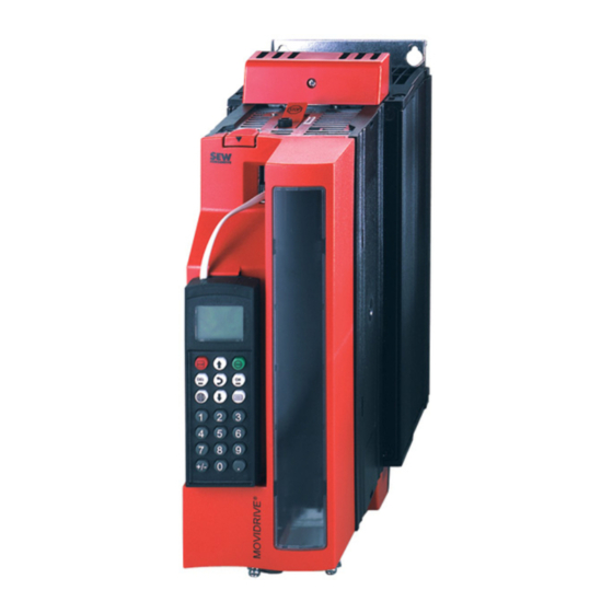
- Page 1 Gearmotors \ Industrial Gear Units \ Drive Electronics \ Drive Automation \ Services ® A5.J25 MOVIDRIVE MDX61B Fieldbus Interface DFI21B INTERBUS with Fiber Optic Cable Edition 04/2004 anual 11264012 / EN...
- Page 2 SEW-EURODRIVE – Driving the world...
-
Page 3: Table Of Contents
1 Important Notes...................... 4 2 Introduction ......................5 Features of the DFI21B option ............... 7 3 Assembly / Installation Instructions..............8 Installing the DFI21B option card ..............8 INTERBUS topologies with DFI21B option ..........11 Bus connection via fiber optics (FO) ............13 Connecting fiber optic connectors.............. -
Page 4: Important Notes
Important Notes Important Notes Handbuch • This manual does not replace the detailed operating instructions! • Only electrical specialists are allowed to perform installation and startup ® observing relevant accident prevention regulations and the MOVIDRIVE MDX60B/61B operating instructions! Documentation • Read through this manual carefully before you start installation and startup of ®... -
Page 5: Introduction
Introduction Introduction Contents of this This user manual describes how to install the DFI21B INTERBUS with fiber optic cable ® manual option card in the MOVIDRIVE MDX61B drive inverter and how to start up ® MOVIDRIVE with the INTERBUS fieldbus system. It also contains an explanation of all settings on the fieldbus option card and connection variants with INTERBUS in the form of small startup examples. - Page 6 Introduction ® In addition, you can route the MOVITOOLS startup and diagnostic software via the existing Ethernet/INTERBUS communication paths without having to establish another diagnostic bus (such as RS-485). Startup Generally, the INTERBUS DFI21B option card has been designed so that all INTERBUS-specific settings, such as process data length and baud rate can be made using the hardware switch on the option card.
-
Page 7: Features Of The Dfi21B Option
Introduction Features of the DFI21B option Features of the DFI21B option Only the transfer medium of the INTERBUS changes for the user through the bus cabling with fiber optic cables, which means bus design, project planning and programming in the control system are not affected by the use of a fiber optic cable. ®... -
Page 8: Assembly / Installation Instructions
Assembly / Installation Instructions Installing the DFI21B option card Assembly / Installation Instructions Installing the DFI21B option card ® • Option cards can only be installed and removed for MOVIDRIVE MDX61B sizes 1 to 6. • Only SEW-EURODRIVE engineers can install or remove option cards for ®... - Page 9 Assembly / Installation Instructions Installing the DFI21B option card Installing and removing an option card 53001AXX ® Figure 2: Installing an option card in MOVIDRIVE MDX61B sizes 1 to 6 1. Remove the two retaining screws holding the card retaining bracket. Evenly pull the card retaining bracket out from the slot (do not twist!).
- Page 10 Assembly / Installation Instructions Installing the DFI21B option card 5. Do not remove the protective cover of the fiber optics output and input until you are ready to plug in the fiber optics connectors (→ Sec. "Installing fiber optics connectors"). 6.
-
Page 11: Interbus Topologies With Dfi21B Option
Assembly / Installation Instructions INTERBUS topologies with DFI21B option INTERBUS topologies with DFI21B option Using the DFI21B option, the drive inverter is connected to an INTERBUS fiber optic remote bus. By setting the baud rate, the DFI21B can be operated in 500 KBaud and 2 MBaud installations. - Page 12 Assembly / Installation Instructions INTERBUS topologies with DFI21B option RS-485/fiber The DFI21B can also be used for the installation of sections of fiber optic lines within an optics mixed RS485 network. operation with 500 KBaud System requirements Interface All INTERBUS G4 interface modules CMD tool Version 4.50 or higher Interbus participants...
-
Page 13: Bus Connection Via Fiber Optics (Fo)
Assembly / Installation Instructions Bus connection via fiber optics (FO) Bus connection via fiber optics (FO) Bus interfacing for DFI21B is accomplished exclusively via fiber optics. Polymer fiber cables and HCS cables may be used for this purpose. Polymer fiber This type of cable is used for distances of up to 70 meters between two Interbus cables participants. -
Page 14: Connecting Fiber Optic Connectors
Assembly / Installation Instructions Connecting fiber optic connectors Connecting fiber optic connectors The fiber optic cable is connected to the DFI21B option card using F-SMA connectors. Two connectors are required each for the incoming and outgoing remote bus (transmit- ter and receiver). SEW-EURODRIVE recommends using F-SMA connectors with bending protection to ensure that the optimum bending radius is maintained. - Page 15 Assembly / Installation Instructions Connecting fiber optic connectors Connecting fiber Access to the side of the unit is required for connecting the fiber optic connectors. If ® optic cable several MOVIDRIVE MDX61B size 0 inverters are installed next to one another, connectors to the respective MDX61B must be removed to connect the fiber optic connector to the MDX61B size 0...
-
Page 16: Setting The Dip Switches
Assembly / Installation Instructions Setting the DIP switches Setting the DIP switches DIP switch The six DIP switches S1-1 to S1-6 on the front side of the option card are used for setting setting the process data length and PCP length as well as selecting the baud rate. [1] Number of process data (1 to 6 words) [2] Number of PCP words (1, 2 or 4 words) Baud rate: [3] OFF: 2 MBaud / [4] ON: 0.5 Mbaud... - Page 17 Assembly / Installation Instructions Setting the DIP switches Setting the pro- A maximum of six INTERBUS data words can be exchanged between the INTERBUS cess data length interface module and the DFI21B option. These data words can be distributed to the and PCP length process data channel and the PCP channel using DIP switches S1-1 to S1-5.
-
Page 18: Display Elements
Assembly / Installation Instructions Display elements Display elements The DFI21B option card has seven LEDs for diagnostics of the INTERBUS system. These LEDs indicate the current state of the DFI21B and the INTERBUS system (Figure Logic Voltage (gn = OK) Remote Cable Check (gr = OK) Bus Active (gn = ok) Remote Bus Disabled (rd = off) - Page 19 Assembly / Installation Instructions Display elements LED UL "U-Logic" (green) State Meaning Fault correction Power supply of bus electronics is present Power supply of bus Verify that the option card is seated correctly and check the electronics is missing 24 V power supply of the inverter. LED RC "Remote Cable Check"...
- Page 20 Assembly / Installation Instructions Display elements LED FO2 "Fiber Optic 2" (yellow) State Meaning Fault correction Monitoring of continuing fiber optic cable. If Check the incoming fiber optic cable for the next participant cable quality, correct connector installation, • possesses an optical line diagnostics, the bending radius, etc.
-
Page 21: Project Planning And Startup
Project Planning and Startup Startup of the drive inverter Project Planning and Startup ® This section describes the project planning and startup of the MOVIDRIVE drive inverter with the DFI21B option in the INTERBUS interface module. Startup of the drive inverter ®... - Page 22 Project Planning and Startup Startup of the drive inverter Startup 1. Enable the power output stage at the terminals. procedure Connect the input terminal DIØØ / X13.1 (function /CONTROLLER INHIBIT) to a +24 V signal (for example, using a device jumper). X13: DI00 DI01...
-
Page 23: Project Planning Of The Interbus System
Project Planning and Startup Project planning of the INTERBUS system 3. Setpoint source = FIELDBUS / control signal source = FIELDBUS To control the drive inverter via fieldbus, set the setpoint source and control signal source to FIELDBUS. - P100 setpoint source = FIELDBUS - P101 control signal source = FIELDBUS 4. - Page 24 Project Planning and Startup Project planning of the INTERBUS system Configuring the The bus structure can be configured online or offline using the CMD tool. bus structure Offline configura- In offline mode, the drive inverter is configured in the CMD tool using the "Edit / Insert tion: Insert with ID with ID code"...
- Page 25 Project Planning and Startup Project planning of the INTERBUS system Online configura- The INTERBUS system can also be installed completely at first, and then the DIP tion: Configuration switches of the DFI21B option can be set. Next, the CMD tool can be used to read in the frame / Read in entire bus structure (configuration frame).
- Page 26 Project Planning and Startup Project planning of the INTERBUS system Representation For easy identification of the drive inverter, CMD tool version 4.50 and higher allows you to copy your own ICO data into the ".\IBSCMD\Pict32\" directory (Figure 15). The "INTERBUS description data for CMD tool" can be found on the SEW website at http://www.SEW-EURODRIVE.com under "Software."...
- Page 27 Project Planning and Startup Project planning of the INTERBUS system Parameter channel The following settings of the parameter channel are necessary if you want to use the PCP channel for setting the inverter parameters in your application: • Message lengths / Transmit / Receive: 243 bytes each •...
-
Page 28: Testing The Pcp Connection
Project Planning and Startup Testing the PCP connection Testing the PCP connection You can use the MONITOR mode of the CMD tool to test the PCP connection to the inverter. The following figures illustrate the procedure for the PCP test. This procedure establishes a PCP connection to the device and reads the parameter list (object directory) saved in the device. - Page 29 Project Planning and Startup Testing the PCP connection the menu. 03722AXX Figure 20: Window for device parameterization using the CMD tool If the device parameters are read in, the project planning of the PCP channel was performed correctly. The read-in process can be aborted. If an error message appears instead of the progress indicator, check the PCP configuration and allocation of CRs.
-
Page 30: The Pcp Interface
The PCP Interface Basic overview The PCP Interface ® With the DFI21B option, the MOVIDRIVE drive inverter offers a standardized interface for parameterization using the "Peripherals Communication Protocol" (PCP). This INTERBUS communications channel gives you access to all drive parameters of the ®... -
Page 31: The Pcp Services
The PCP Interface The PCP services ® Apart from the "CMD tool", the higher-level computer (Windows NT) is also running the ® INTERBUS "@utomationXplorer" and "MOVITOOLS " for programming and parame- terization of SEW drive inverters on the INTERBUS. This arrangement allows for using the existing bus infrastructure for startup and maintenance. - Page 32 The PCP Interface The PCP services Establishing the The PCP service "Initiate" is used to establish a communications link for parameteriza- ® communication tion between an INTERBUS interface module and the MOVIDRIVE drive inverter. connection with Communication is always established by the INTERBUS interface module. As the "Initiate"...
-
Page 33: Parameters In The Object List
The PCP Interface Parameters in the object list Parameters in the object list Using the PCP services "Read" and "Write", the INTERBUS interface module can access all parameters defined in the object list of the DFI21B. All drive parameters that can be accessed via the bus system are defined as communications objects in the static object list of the DFI21B. - Page 34 The PCP Interface Parameters in the object list "Download The "Download parameter block" object can be used to write a maximum of 38 ® parameter block" MOVIDRIVE drive parameters at the same time with a single write service. object Consequently, this object offers the possibility to set the parameters of the drive inverter, for example during the starting phase, with a single call of the write service.
- Page 35 The PCP Interface Parameters in the object list The WRITE service to the "download parameter block" object on the fieldbus option card starts a parameterization mechanism that writes sequentially all parameters listed in the user data area of the object into the DRAM and, by doing so, sets the parameters of the drive inverter.
- Page 36 The PCP Interface Parameters in the object list The following table shows the structure of this communications object. Refer to the ® MOVIDRIVE "Fieldbus Unit Profile and Parameter List" documentation for information about the structure of the parameter channel. Octet Meaning Manage- Reserved...
- Page 37 The PCP Interface Parameters in the object list The inverter now executes the service coded in the parameter channel and re-enters the service confirmation in the parameter channel. The master receives the service ® confirmation with the next read access to the "MOVILINK cyclic parameter channel."...
- Page 38 The PCP Interface Parameters in the object list Parameter channel If a write type service is executed via the acyclic parameter channel (e.g. write performs a write parameter or write parameter volatile), the inverter responds with the current service service confirmation after the service has been executed.
-
Page 39: Return Codes
The PCP Interface Return codes ® The MOVILINK acyclic parameter channel in handled only locally on the fieldbus option card and is defined as shown in the following table. Index: 8299 Object code: 7 (simple variable) Data type index: 10 (octet string) Length: Local address: Password:... - Page 40 The PCP Interface Return codes Error code The error code element allows for a more detailed identification of the error cause within the error class and is generated by the communications software of the fieldbus card in case of a faulty communication. For error class 8 = other error, only error code = 0 (other error code) is defined.
-
Page 41: Application Examples
Application Examples Control via process data Application Examples This section shows small application examples for process data exchange and parameterization of the drive inverter via PCP interface. Control via process data The control of the drive inverter via process data is accomplished through simple reading/writing of program addresses to which the INTERBUS process data of the drive inverter are mapped. -
Page 42: Representation Of Coding Examples
Application Examples Representation of coding examples Representation of coding examples The coding examples shown in the following sections are presented in the same way as they are described in the INTERBUS user manual "Peripherals Communication Protocol (PCP)" by Phoenix Contact. All information of a PCP service is represented word by word in column format, i.e. -
Page 43: Reading A Drive Parameter
Application Examples Reading a drive parameter Reading a drive parameter The "Read" service is used for reading a drive parameter (with index 8800). All drive parameters are generally 4 bytes long (1 double word). Example Reading P130 ramp t11 UP CW (index 8470dec = 2116hex) Word Meaning Coding (hex) -
Page 44: Writing A Drive Parameter
Application Examples Writing a drive parameter Writing a drive parameter The "Write" service is used for writing a drive parameter (with index 8800). All drive parameters are generally 4 bytes long (1 double word). Example Writing the ramp time 1.65 s to P130 "Ramp t11 UP CW" Index: 8470dec = 2116hex Value: 1.65s = 1650ms = 1650 dec = 0000 0672 hex) The parameter data are represented in Motorola format (Simatic format) as follows:... -
Page 45: Writing Ipos Variables/Parameters Via Movilink® Parameter Channel
Application Examples Writing IPOS variables/parameters via MOVILINK® parameter channel ® Writing IPOS variables/parameters via MOVILINK parameter channel ® The drive inverters offer a special parameter access via MOVILINK parameter channel plus® for universal write access to all drive inverter data (parameters, IPOS variables, plus®... - Page 46 Application Examples Reading IPOS variables/parameters via MOVILINK® parameter channel plus® Example Reading the IPOS variable H0 = Index 11000 dec (2AF8 hex) ® A detailed explanation of the MOVILINK parameter channel can be found in the ® "MOVIDRIVE Fieldbus Unit Profile and Parameter List" manual Word Meaning Coding (hex)
-
Page 47: Writing Ipos Variables/Parameters Using The Download Parameter Block
Application Examples Writing IPOS variables/parameters using the download parameter block Word Meaning Coding (hex) Message_Code = Read_Confirmation 80 81 Parameter_Count 00 03 Invoke_ID Comm._Reference 00 02 Error_Class Error_Code 08 00 Additional_Code 00 10 Bits 15 ... 8 7 ... 0 You can use the return codes for evaluating a negative message. -
Page 48: P Hz
Technical Data DFI21B option Technical Data DFI21B option DFI21B option Part number 824 604 1 Supported baud rates 500 kbaud and 2 Mbaud, selectable via DIP switch Connection technology • Remote bus input: 9-pole sub D connector • Remote bus output: 9-pin sub D socket •... -
Page 49: Index
Index Fiber Optic 1 Fiber Optic 2 Abort Fiber optic connectors Abort connection Additional code Application example Assembly Assigning process data HCS cable ID code Baud rate Initiate Bus Active Installation Bus interfacing Interface type Bus structure configuration Internal communication error Cable Check Last PCP index Cable types... - Page 50 PCP connection Writing parameters PCP interface PCP length PCP services performance characteristics Polymer fiber cables Process data channel Process data length Process data length, PCP length Process data manager Program setting Project planning Read read in bus structure Read in configuration frame Read parameter list Read parameter values Reading a drive parameter...
- Page 52 Gearmotors \ Industrial Gear Units \ Drive Electronics \ Drive Automation \ Services How to drive the world With people who With drives and con- With a comprehensive With uncompromising think fast and With a service network trols that automatically knowledge in the most quality whose high develop the...
Need help?
Do you have a question about the MOVIDRIVE MDX61B and is the answer not in the manual?
Questions and answers