
Subscribe to Our Youtube Channel
Related Manuals for JTS RU-901Du


Summary of Contents for JTS RU-901Du
- Page 1 PROFESSIONAL CO., LTD. No. 148, 9th Industry Road, Ta-Li Industrial Park, Taichung City, Taiwan, R.O.C. Tel: 886-4-24938803 Fax: 886-4-24914890 E-mail: jts@jts.com.tw www.jts.com.tw 59508-118-01...
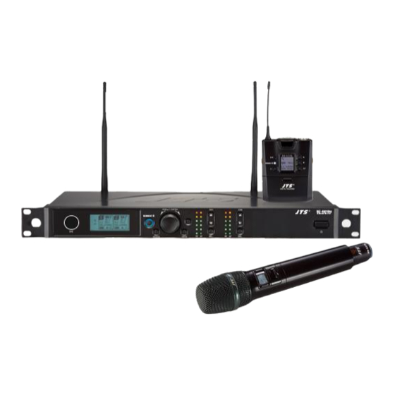
- Page 2 UHF PLL Transmitter UHF PLL RU-901Du /RU-G3TH /RU-G3TB Instruction Manual With JTS Ultrasonic Synchronizing Technology...
- Page 3 One year product warranty Product Model Equipment serial number Contact Customer number name Address Purchase date Selling store stamp Be sure to put store stamp and fill in purchase date for the warranty to be effective! Warranty description 1. Be sure to put the warranty label indicating purchase date on the bottom of equipment to ensure your interest in maintenance and service.
- Page 4 3-3 UHF PLL body-pack transmitter // RU-G3TB 3-4 Optional condenser microphone 4. Description of parts 4-1 UHF PLL Dual-channel True Diversity receiver // RU-901Du 4-2 UHF PLL hand-held transmitter // RU-G3TH 4-3 UHF PLL body-pack transmitter // RU-G3TB 4-4 Optional remote mute switch PT-RMS...
-
Page 5: Notes For System Operations
1. Notes for system operations • Before connecting the power, check that the power requirement shown on the unit is the same as the power output on the adaptor supplied. • Do not leave the unit at where the humidity and temperature are high. •... -
Page 6: Specifications
3. Specifications 3-1 UHF PLL Dual-channel True Diversity receiver // RU-901Du Frequency Oscillation Mode Phase-locked loop (PLL) Carrier Frequency Range 470~960 MHz Remoset Frequency Ultrasonic Diversity Antenna diversity Bandwidth 36MHz Signal/Noise Ratio >105dB(A) Total Harmonic Distortion (Thd) <0.6%@1KHz Receiving Sensitivity -95dBm ,... - Page 7 3-2 UHF PLL hand-held transmitter // RU-G3TH Frequency Oscillation Mode Phase-locked loop (PLL) Carrier Wave Frequency Range 470~960 MHz Remoset Frequency Ultrasonic RF Power Output 10mW/50mW(as per local regulations) RF Stability <±10KHz @ Fc Modulation Frequency Shift ±48KHz Harmonic Radiation <-50dBc Display By LCD+LED...
-
Page 8: Optional Condenser Microphone
3-3 UHF PLL body-pack transmitter // RU-G3TB Frequency Oscillation Mode Phase-locked loop (PLL) Carrier Wave Frequenc y 470~960MHz Range Remoset Frequency Ultrasonic RF Power Output 10mW/50mW(as per local regulations) RF Stability <±10KHz @ Fc Modulation Frequency Shift ±48KHz Harmonic Radiation <-50dBc Mute, auto off, input level attenuation, sensitivity Functions... -
Page 9: Headset Microphone
Headset microphone Model CM-214i CM-214Ui CM-214ULi 801C4 4P Mini XLR 801C3 (3P Mini XLR) Connector (4P Mini XLR) 801C4 (4P Mini XLR) 801CS (3.5 stereo plug) 801C3 (3P Mini XLR) 801CR Option 801CS (3.5 stereo Connector plug) 801CR 60~15,000 Hz 30~18,000 Hz 100 ~ 18,000Hz Frequency Response... - Page 10 Ear-hook microphone // CM-801 CM-804i CM-8015 CM-825i Model No CM-801 / CM-804i CM-8015 / CM-825i Connector 801C4 (4P Mini XLR) 801C4 (4P Mini XLR) 801C3 (3P Mini XLR) 801C3 (3P Mini XLR) Option Connector 801CS (3.5 stereo plug) 801CS (3.5 stereo plug) 801CR 801CR Frequency Response...
-
Page 11: Description Of Parts
4. Description of parts 4-1 UHF PLL Dual-channel diversity receiver( True Diversity ) // RU-901Du Front panel Power ON/OFF: ON:push once to turn on. OFF:push and hold until ''Power OFF'' is shown on the LCD to turn off. EXIT: Push exit to cancel a selection or exit from the current menu when RU- 901Du is in the ''setting menu.''... - Page 12 PUSH / CONTROL R -901Du Channel Receiver SEL. SEL. SETUP EXIT Rear panel DC power socket: for 12~15V DC / 1A power supply XLR audio jack: balanced audio signal output XLR audio jack: balanced audio signal output after mixing Ø6.3 audio output jack: unbalanced audio signal output after mixing Antenna A (B) input terminal: BNC antenna input jack that also provides DC12V/100mA output.
- Page 13 Content Displayed under the Non-Setting Mode: :Antenna Selection A/B. The Receiver is mute. : Transmitter Battery Level :Frequency (Group/Channel) : Frequency : Key Lock (Key Lock ON) : Volume : Output attenuation ON Setup Menu RX1: Set the Receiver's Channel 1. RX2: Set the Receiver's Channel 2. 1: Set the Receiver's Channel 1.
- Page 14 4-2 UHF PLL hand-held transmitter // RU-G3TH Power: push to turn the transmitter on. When the transmitter is on, push and hold for 2 seconds to turn it off. Mute: while the transmitter is on, switch Mute up to talk and down to mute. If the transmitter is off, switch the Mute up to turn the unit on.
- Page 15 Indicators Green Battery > 2V Flashing green Microphone mute Battery ≤ 2V Alternating red and green Microphone mute (and battery low) Blue Pairing successful Flashing blue Data receiving error Others Battery charging is supported. The transmitter turns off automatically when charging.
-
Page 16: Lcd Display
4-3 UHF PLL body-pack transmitter // RU-G3TB LCD display Ultrasonic receiving unit: it receives the pairing signals from the ultrasonic transmission unit at the receiver end. REMOSET indicator: Blue:Pairing successful Flashing blue:Date receiving error Power: (1)On: push the power button Off: push and hold the power button for 2 seconds till the display shows “Power Off. -
Page 17: Optional Remote Mute Switch Pt-Rms
4-4 Optional remote mute switch PT-RMS PT-RMS 4-5 Optional Condenser Microphone Lavaliere Microphone // CM-501 CM-201i CM-125i Clip 4 Pin Mini XLR 3 Pin Mini XLR Option 3.5 Stereo Plug Option 4Pin Hirose connecter Option Windscreen CM-501 CM-201i CM-125i WIRELESS MICROPHONE SYSTEM... - Page 18 Headset Microphone // CM-214i / CM-214Ui / CM-214ULi / CM-235i / CX-504 Gooseneck Adjustable headband Headband 4 Pin Mini XLR 3 Pin Mini XLR Option 3.5 Stereo Plug Option 4Pin Hirose connecter Option Windscreen CM-214i CM-214Ui CM-214ULi Standard : 4 Pin Mini XLR 3 Pin Mini XLR 3.5 Stereo Plug CM-235i...
- Page 19 Ear-hook Microphone // CM-801 / CM-804i / CM-8015 / CM-825i Boom Adjustable Headband Adjustable ear hook Detchable Cable CM-801 Cable Clip Windscreen 4 Pin Mini XLR 3 Pin Mini XLR Option 3.5 Stereo Plug Option 4Pin Hirose connecter Option CM-804i CM-8015 CM-825i WIRELESS MICROPHONE SYSTEM...
- Page 20 Compatible Instrument Microphone // CX-500 / CX-500F / CX-520 / CX-508W / CX-516W Gooseneck Clip Bracket Volume Control Windscreen 4 Pin Mini XLR CX-500 CX-500F CX-520 CX-508W CX-516W...
- Page 21 4-6 Accessories AC/DC adaptor Switching Power Supply(100V~240V , 50~60Hz) Linear Power Supply (220V , 50Hz) Option Linear Power Supply (220V , 60Hz) Option Screwdriver DR-900 Dual Rack Adaptor Option Option RM-901 Rack Mount Kit RP-900 Panel Cover Option AF output cable (with Φ6.3 plug at both ends) GC-80/GC-100 Guitar Cable Option GC-80L/GC-100L Guitar Cable...
-
Page 22: Preparing Procedures
5. Preparing Procedures 5-1 How to connect the receiver// RU-901Du 1. Connect the audio output of receiver to mixer or amplifier 1.1RU-901Du: (1) The XLR output jack or 6.3mm unbalance output jack can be selected individually to connect the AF output to a mixer or amplifier for volume control. - Page 23 5-2 Transmitter installation // RU-G3TH The Mute button on the hand-held unit also triggers the power-on. That’s why the unit is on as soon as the batteries are replaced. Therefore, if you do not wish to turn on after changing the batteries, keep the Mute switch on mute. 1.
- Page 24 6. Instructions for use 6-1 How to use// RU-901Du Press and hold the SETUP key for 2 seconds to enter the Setup Menu. Trun the Rotary Switch to select the item to be set, and press SETUP again to enter the settings.
- Page 25 ◎The Scanning Function Scan All Groups. Press the SETUP key to start scan- ning. After the scan is completed, the “Scan Results List” screen will be displayed automatically. Users can also click on the menu to enter the “Scan Results List” directly.
-
Page 26: Output Attenuation
右旋 to search for the next available Channel. Press the SETUP key to save the settings. ◎Receiver Sensitivity +10 ~ -5: The higher the value, the lower the Receiver Sensitivity; the lower the value, the higher the Receiver Sensitivity. Default Value is 0. ◎Output Attenuation 右旋... - Page 27 Sensitivity Scope of Adjustment: -15dB~+15dB;Default Value is 0. Input Attenuation Audio input is attenuated by 20dB. (Depend- ing on whether the transmitter has this function) Not Attenuated (Default Value) This function only applies to the Waist-Mounted Trans- mitter RU-G3TB. Radio Frequency Power High High Transmitting Power 50mW Low Transmitting Power 10mW(Default Value)
- Page 28 Synchronization Options Trun the Rotary Switch to select synchronize transmission of the setup items, and then press the SETUP key to perform the selection action. □ Frequency □ Sensitivity □ Input Attenuation (RU-G3TB only) □ Radio Frequency Power □ Automatic shut-down □...
- Page 29 ◎Mixed Output 混音開始 混音開關 將RX1和RX2的聲音混在一起,然後由RX2輸出。 ◎Reset to original manufacturer settings ◎Exit the Setup Screen. Press the SETUP key to exit the setup screen and return to the home screen. WIRELESS MICROPHONE SYSTEM...
- Page 30 Pairing Once the parameters are set, push the “ ” button and the digital pairing data will be sent to the transmitter via ultrasonic transmitter for parameter synchronization. The indicator will flash rapidly while the data are being transmitted. When the synchronization is completed, the receiver will receive the corresponding data and the indicator will stop flashing.
- Page 31 6-2 How to use// RU-G3TH/G3TB Push and hold the SET button for 2 seconds to enter the setting mode, and push the▲/▼button to select different parameters. Push the SET button again to save and exit the setting mode. ◎ FREQ: frequency setting In 1MHz Select frequency with ▲/▼...
- Page 32 ◎ RFP: RF microphone power rFP Lo 10mW(default) rFP Hi 50mW The RF output is LOW. The RF output is Hi. ◎ AUTO-OFF: Automatic microphone off countdown under mute status This function is deactivated 1 minute countdown to turn off 10 minute countdown to turn off 30 minute countdown to turn off (The default setting is 10 minute.)
- Page 33 Plug the connector into input socket on the body-pack transmitter. MIC IN (3) Instrument Microphones The system is compatible with JTS various instrument microphones. For detail please refer to user’s manuals of these microphones. WIRELESS MICROPHONE SYSTEM...
- Page 34 (4) Ear-hook Microphone 1. Lightweight Dual Ear Hook Microphone Try on whether the headset is fit. Adjust the headband to a suitable width. Tighten or loosen the curve of the ear-hook by twisting the loop or expanding it. Curve and bend the boom to fit your face. Attach the detachable cable to a suitable place by a cable clip.
-
Page 35: Notes For The Product
7. Notes for the product For the best signal receiving quality, always keep the receiver within 3m of the transmitter. The receiver and transmitter shall be away from other metal objects, preferably 50cm or farther. Do not point the microphone directly to a speaker, or there will be feedbacks. It is recommended to hold the transmitter (microphone) at the middle section for the best pickup.
Need help?
Do you have a question about the RU-901Du and is the answer not in the manual?
Questions and answers