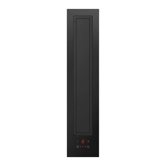
V-ZUG DSMS Installation Instructions Manual
Operating mode: extraction/recirculation
Hide thumbs
Also See for DSMS:
- Operating instructions manual (28 pages) ,
- Operating instructions manual (12 pages) ,
- Operating instructions manual (24 pages)
Advertisement
Quick Links
Installation instructions
Range hood
Operating mode: Extraction/recirculation
DSMS
The appliance should be installed by qualified personnel only.
Each step must be carried out and checked in full in the order specified.
Validity
These installation instructions apply to:
64005 (DSMS, construction width 11 cm)
General notes
If other firing systems are being used at the same time (e.g. wood, gas, oil or coal fired heating appliances), safe op-
eration is only possible providing a room negative pressure of 4 Pa (0.04 mbar) is not exceeded at the location of the
appliance.
Risk of toxic fumes! An adequate flow of fresh air must be guaranteed e.g. via non-closable openings in doors or
windows and in combination with an air-intake/exhaust-air wall box or by other technical means.
The use of the range hood together with a gas fired appliance is not permitted.
Efficient repairs can only be guaranteed if it is possible to de-install the complete appliance at any time without caus-
ing any damage.
Identification plate
▸
The identification plate is located in the base unit on the side panel of the fan motor.
▸
A second identification plate is included in the scope of delivery and should be retained for the purpose of appliance identifica-
tion.
Scope of delivery
R
K
S1 (12×)
G
A
A
Drip tray frame
E
Control unit
F
Metal grease filter
Appliance housing
G
K
Control cable
Ventilation outlet
L
M
Fan motor
S2 (4×)
T
F
U (2×)
1
V (2×)
T
L
M
N
Mains cable length 1.8 m
Q
Flat channel system
R
Frame
Exhaust air duct
T
U
Spacer profile
Connecting elements
V
1030019-R04
10/05/2017
N
E
Advertisement

Summary of Contents for V-ZUG DSMS
- Page 1 Each step must be carried out and checked in full in the order specified. Validity These installation instructions apply to: 64005 (DSMS, construction width 11 cm) General notes If other firing systems are being used at the same time (e.g. wood, gas, oil or coal fired heating appliances), safe op- eration is only possible providing a room negative pressure of 4 Pa (0.04 mbar) is not exceeded at the location of the...
- Page 2 1030019-R04 Installation instructions 10/05/2017 Range hood Operating mode: Extraction/recirculation DSMS Extraction mode The extracted air must not be fed into a chimney which is used for exhausting fumes from appliances burning gas or other fuels. Observe the local fire regulations.
- Page 3 1030019-R04 Installation instructions 10/05/2017 Range hood Operating mode: Extraction/recirculation DSMS Dimensions 548–698 479–629 ø190 The connection between the hob hood and the exhaust air duct T can be to the left or right. The ventilation outlet L can be fed through one of the four sides; this, however, can change the installation type. Standard ventilation outlet L is by means of flat channel or pipe ø150 mm.
- Page 4 Installation instructions 10/05/2017 Range hood Operating mode: Extraction/recirculation DSMS Combination installation Flush installation Flush-mounted installation with additional intermediate supports K requires the accessory intermediate support set H63789 (con- tains two intermediate supports). Flush-mounted combination installation is described in document 1014381.
- Page 5 10/05/2017 Range hood Operating mode: Extraction/recirculation DSMS Surface-mounted installation Surface-mounted installation requires the accessory side strip set 1028587 and either the intermediate support K 1019199 (black) or 1014361 (stainless steel). Articles are available for order as accessories. Surface-mounted combination installation is described in document 1013773.
- Page 6 1030019-R04 Installation instructions 10/05/2017 Range hood Operating mode: Extraction/recirculation DSMS Installation overview base unit Wall installation with depth of ≥600 mm Wall/island installation with depth of ≥700 mm ≥600 ≥700 548–698 548–698 479–629 479–629 ≤400 ≤500 ≤300 ≤400 Island installation with depth of ≥800 mm ≥800...
- Page 7 1030019-R04 Installation instructions 10/05/2017 Range hood Operating mode: Extraction/recirculation DSMS Installation Before installation determine whether the exhaust air duct should be to the left or right. ▸ Fasten frame R to housing G with 4 screws S1. ▸ Insert metal grease filter F from the side into collection tray A.
- Page 8 Installation instructions 10/05/2017 Range hood Operating mode: Extraction/recirculation DSMS For flush installation: Prepare the cut-out according to cementing-in instructions J004130. ▸ Place the hob hood into the prepared cut-out from the top and onto the intermediate supports K and align.
- Page 9 1030019-R04 Installation instructions 10/05/2017 Range hood Operating mode: Extraction/recirculation DSMS Installation type: Extraction or recirculation mode. Observe recirculation box U and flat channel system options (accessory available for order). ▸ The individual components required must be taken into ac- count during planning! ▸...
- Page 10 1030019-R04 Installation instructions 10/05/2017 Range hood Operating mode: Extraction/recirculation DSMS ▸ Cut the exhaust ducting components T to size according to installation type and assemble using connecting elements V. ▸ Insert exhaust ducting T into motor housing. ▸ S2 (4×) Fasten exhaust ducting T to hob hood with 4 screws S2.
- Page 11 Installation instructions 10/05/2017 Range hood Operating mode: Extraction/recirculation DSMS Extraction mode There is a danger of toxic fumes developing if the range hood is operated at the same time as an ambient air-depend- ent firing system! Conversion kits and suitable flat channel systems are available for order as accessories.
- Page 12 10/05/2017 Range hood Operating mode: Extraction/recirculation DSMS Recirculation mode Conversion kits and suitable flat channel systems are available for order as accessories. For recirculation mode with recirculation box, ensure access for maintenance purposes and also ensure the blow-out opening is at least 500 cm²...


Need help?
Do you have a question about the DSMS and is the answer not in the manual?
Questions and answers