Table of Contents
Advertisement
Quick Links
Advertisement
Table of Contents

Related Manuals for Veeder-Root Mag Plus


Summary of Contents for Veeder-Root Mag Plus
- Page 1 ● Manual No: 577013-987 Revision: D Mag Plus Density Probe Assembly Guide...
- Page 2 Customer Service will work with production facility to have the replacement product shipped as soon as possible. If “lost” equipment is delivered at a later date and is not needed, Veeder-Root will allow a Return to Stock without a restocking fee.
-
Page 3: Table Of Contents
Attaching Probe Canister Stabilizer Rings (3- & 4-Inch Risers) ........4 Assembling Floats onto Probe Shaft ................6 Attaching Cable Connector to Probe Canister ..............6 Figures Figure 1. Identifying Mag Plus Density Probe Installation Kit Components ...3 Figure 2. Installing Probe Canister Insulator Sleeves ..........4 Figure 3. -
Page 4: Important
Introduction This manual describes how to identify and assemble the components of the Mag Plus Density Probes. Instructions are included for assembling floats onto the probe’s shaft, attaching spacer rings to the probe’s canister, and attaching the probe’s cable to the probe. -
Page 5: Mag Plus Density Probe Installation Kits
Mag Plus Density Probe Installation Kits Installation Kits Available Mag Plus Density Probe installation kits are listed in Table 1 and Table 2. The kit components can be identified in Figure 1. Table 1. Installation Kit (with seal kit) - P/N 886002-XXX or P/N 886000-XXX Qty. -
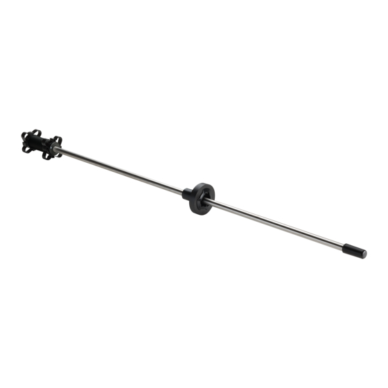
Page 6: Figure 1. Identifying Mag Plus Density Probe Installation Kit Components
Cable BOOT This Density Code etched along this surface (example) Adjustable Spacers Insulating Sleeves (3- and 4-Inch Risers) (2-Inch Risers) WATER/DENSITY FLOAT 987-1.eps CANISTER SPACERS (Type depends on kit ordered) Figure 1. Identifying Mag Plus Density Probe Installation Kit Components... -
Page 7: Assembling Probe Components
Assembling Probe Components Attaching Probe Canister Insulator Sleeves (2-Inch Risers) 1. Open the Probe shipping carton so that you have access to the probe. Also open the installation kit. 2. Install the two canister sleeves onto the probe canister as shown in Figure 2. 987-3.eps Figure 2. -
Page 8: Figure 3. Installing Probe Canister Spacer Rings
Assembling Probe Components Attaching Probe Canister Stabilizer Rings (3- & 4-Inch Risers) After setting arms (see insert) install top stabilizer ring. Orient locking tabs as shown, and then slide ring over top of canister until tabs snap into groove in canister. CANISTER STABILIZER RING SETTINGS 3-inch riser set 4 arms of ring... -
Page 9: Assembling Floats Onto Probe Shaft
Assembling Probe Components Assembling Floats onto Probe Shaft Assembling Floats onto Probe Shaft All sizes of the Product and Water/Density Floats and the Boot are assembled on the probe shaft in the exact sequence and orientation shown in Figure 4. IMPORTANT! Failure to push the boot as far as possible onto the probe shaft could cause the boot and float(s) to fall into the tank. -
Page 10: Table 3. Record Of Installed Probe Float And Density Codes By Tank
3. Save the remaining kit components and refer to the appropriate Site Prep Manual to install the probe in the tank and connect it to the field wiring from the console. 4. Refer to the appropriate console setup instructions to configure the Mag Plus Density Probe. Table 3. Record of Installed Probe Float and Density Codes by Tank... - Page 11 For technical support, sales or other assistance, please visit: www.veeder.com...
Need help?
Do you have a question about the Mag Plus and is the answer not in the manual?
Questions and answers