Table of Contents
Advertisement
Quick Links
Advertisement
Table of Contents

Related Manuals for Veeder-Root Mag-FLEX


Summary of Contents for Veeder-Root Mag-FLEX
- Page 1 Manual No: 577014-038 Revision: C Mag-FLEX Probe Installation Manual - EU Version...
- Page 2 Connection of any sensor not supplied by Gilbarco Veeder- Root will void the product warranty. Gilbarco Veeder-Root makes no warranty of any kind with regard to this publication, including, but not limited to, the implied warranties of merchantability and fitness for a particular purpose.
-
Page 3: Table Of Contents
Lightning And Surge Protection................5 Mag-FLEX Probe Overview Product Description ......................6 Mag-FLEX Technical Data ....................7 Mag-FLEX Probes Part Number Specification ..............8 Mag-FLEX Spare Parts And Accessories...............10 Fafnir BA-350 Protection Device (Surge Protector) ............10 Information On Safe Use ..................10 Information On Safe Mounting Resp. Demounting..........10 Information On Safe Installation ................10... - Page 4 Tables Table 1. Temperature Class Ta Tf ................3 Table 2. Dimensions for Mag-FLEX Probe Tank Opening ........6 Table 3. ATEX Version - For TLS4/4B pre-Version 6A or TLS-450 pre-Version 4M or TLS-3xx & TLS 2 / 2P All Versions ....8 Table 4.
-
Page 5: Tank Gauge Requirements
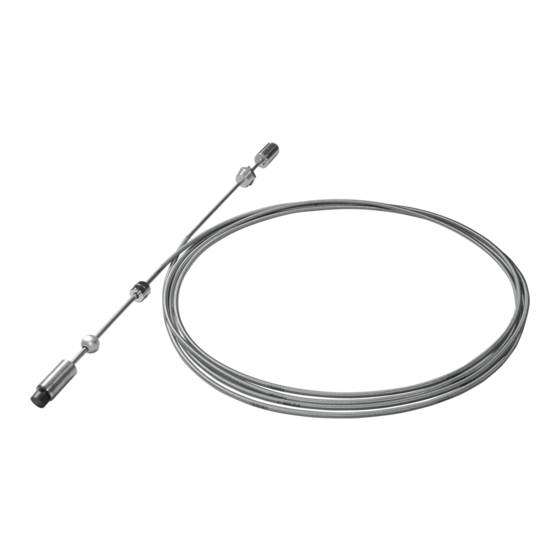
The Mag-FLEX is a digital flexible probe designed to measure product temperature, product level and water level in large storage tanks. The Mag-FLEX probes can measure liquid heights of up to 9.9 metres with TLS2 consoles and up to 22 metres with TLS-3XX and TLS4/TLS-450 consoles (reference table below). For storage vessels with maximum liquid levels up to 3.66 metres it is recommended that a Veeder-Root Mag Plus probe be used. -
Page 6: Safety Symbols
Safety Marking The Mag-FLEX Probe is an intrinsically safe apparatus designed to be installed in Zone 0 and on the boundary of hazardous areas between Zone 1 and Zone 0, i.e., the wall of a fuel tank. Associated apparatus connected to this product must have a compatible barrier and/or shall have suitable entity parameters. -
Page 7: Ec-Type Certificates For An Intrinsically Safe System
IIA or IIB dangerous substances. The Mag-FLEX is in compliance with the Directive 94/9/EC (ATEX). The sample of the type has been tested by TÜV NORD CERT GmbH, ID 0044, Langemarckstraße 20, 45141 Essen, Germany, and approved by the issue of the EC type certificate, where the complete name Mag Plus 1 Flex is used. -
Page 8: Before You Begin
The Mag-FLEX Probe is part of the TLS Monitoring System and can be installed in equipment Category 1 and is suitable for use in a Zone 0 hazardous location. Extreme care must be taken when determining the suitability of the installation conditions and operation of the TLS Monitoring System. -
Page 9: Equipotential Bonding
(not provided) and the saddle clamp and grounding screw on the probe housing. All TLS Consoles provide an alarm if either of the two wires to the Mag-FLEX probe is disconnected or short circuited due to a malfunction. If a probe must be serviced or replaced, observe any required relaxation time prior to opening any covers and removing the probe. -
Page 10: Mag-Flex Probe Overview
The Mag-FLEX Probe has a weight and magnet at the base of the probe to give stability, suitable for use in a wide range of products and available with or without water detection. The Mag-FLEX Probe with standard water float uses a process connection requiring a 1-½”... -
Page 11: Mag-Flex Technical Data
Mag-FLEX Probe Overview Mag-FLEX Technical Data Mag-FLEX Technical Data • Level accuracy: Ø 47,2mm Earth Connector M12 coupling (Probe connector) - Precision: +/- 2mm - Repeatability: +/- 0.5mm - Resolution: 0.001 mm • Digital communication Probe canister • Temperature sensing M6 x 10mm socket cap screw •... -
Page 12: Mag-Flex Probes Part Number Specification
55.81 59.06 17010 18000 59.08 62.33 18010 19000 62.36 65.61 19010 20000 65.64 68.89 20010 21000 68.93 72.18 21010 22000 *For example, to order a Mag-FLEX Probe for Diesel, min./max. length 42.68 – 45.93 feet (in green), order P/N 889561-212. -
Page 13: Table 4. Atex Version - For Tls4 & 4B From Version 6A Or
17010 18000 59.08 62.33 18010 19000 62.36 65.61 19010 20000 65.64 68.89 20010 21000 68.93 72.18 21010 22000 *For example, to order a Mag-FLEX Probe with No Water Detect, min./max. length 49.25 – 52.50 feet (in orange), order P/N 889561-614. -
Page 14: Mag-Flex Spare Parts And Accessories
908704 Fafnir BA-350 Protection Device (Surge Protector) This section details safety information that is pertinent to the Fafnir Surge Protector only. The Veeder-Root Surge Protector is certified by UL/DEMKO. The overvoltage protection device is intended to protect intrinsic safety sensor apparatus from overvoltage eventually caused by atmospheric static electricity and conveyed by the connecting cables. -
Page 15: Information On Safe Adjustment
There are no required safety adjustments. INFORMATION ON SAFE PUTTING INTO SERVICE Before putting the Mag-FLEX probe into service, double check connections and mounting. INFORMATION ON SAFE MAINTENANCE AND REPAIRING In general, the equipment is maintenance free. Defective equipment must be returned to the manufacturer or one it’s representatives. -
Page 16: Mag-Flex Probe Length Calculation
Probe Handling It is important to handle the Mag-FLEX probe with care at all times during the installation. Avoid excessive bending of the probe especially at the points the ridged sections meet with the flexible shaft. Below you can see examples of mishandling that would cause irreversible damage to the probe and invalidate the terms of warranty. -
Page 17: System Safety Layout
Installer’s responsibility to ensure that the installation complies with all relevant local and national legislation and codes of practice. Do not run the Mag-FLEX probe cable from the tank to the TLS Console in the same cable duct as non-intrinsically safe wiring. -
Page 18: Mag-Flex Installation And Handling Procedure
Installation requires a minimum of two people to allow correct handling of the probe. Please note that the flexible and therefore fragile nature of the Mag-FLEX probe makes it more prone to mechanical shock. The probe must not be unpacked until it has been brought to its place of installation and where possible unpacked at the Tank top. The probe corrugated shaft is supplied in a 1 meter diameter coil this coil MUST not be reduced in size. -
Page 19: Mag-Flex Probe Installation
Mag-FLEX Installation And Handling Procedure Mag-FLEX Probe Installation Mag-FLEX Probe Installation 1. Unpacking the probe The probe shipping box is 1.1m square and12cm deep. The probe is coiled to a diameter of approximately 1m. The probe should not be unpacked until the tank is ready to accept it. - Page 20 Mag-FLEX Installation And Handling Procedure Mag-FLEX Probe Installation 3. Probe held ready for installation The coil should be held as shown maintain- ing the coiled shape to prevent kinking. 4. Process Connection With the 5mm hex key, loosen the socket cap screw and gland.
- Page 21 Mag-FLEX Installation And Handling Procedure Mag-FLEX Probe Installation 6. Feeding the probe into the tank Unroll the corrugated shaft as the probe is lowered into the tank taking care to avoid chafing on the tank entry. Corrugated shaft lowered into tank...
- Page 22 Mag-FLEX Installation And Handling Procedure Mag-FLEX Probe Installation 9. Fitting the process connection Apply sealant to the thread of the process connection. Carefully lower the process connection into the tank entry fitting. Screw in and tighten using a 55mm WAF spanner..
-
Page 23: Figure 2. Ba-350 Surge Protector Installation Examples
Surge Surge Protector (P/N 848100-001) Protector to tank (P/N 848100-002) Riser pipe ground Seal off Conduit with Probe field wiring to ATG Example Wireless Installation Example Hardwired Installation Figure 3. Veeder-Root Single- And Dual-Channel Surge Protector Installation Examples... -
Page 24: Mag-Flex Probe-To-Surge Protector Wiring Connections
Mag-FLEX Installation And Handling Procedure Mag-FLEX Probe-To-Surge Protector Wiring Connections Mag-FLEX Probe-To-Surge Protector Wiring Connections BA-350A SURGE PROTECTOR - WIRED INSTALLATIONS ONLY 1. Connecting the probe leader cable - Connect the leader cable supplied with the probe to the M12 connector located on the top of the probe canister. -
Page 25: Veeder-Root Surge Protectors
Mag-FLEX Installation And Handling Procedure Mag-FLEX Probe-To-Surge Protector Wiring Connections 4. Grounding the surge protector to the tank An 10 gauge (4mm²) eearth cable NOTICE must be connected between the surge protector and tank ground connection. According to the provision of EN/ IEC 60079-14, the minimum size of the earth cable shall be 4 mm². -
Page 26: Figure 5. Splice Connections
Mag-FLEX Installation And Handling Procedure Mag-FLEX Probe-To-Surge Protector Wiring Connections 2. Make the connections to the four black and white wires in the surge protector using wire nuts as shown in Figure 5. Depending on the installation, cut off the TLS console or Transmitter cable’s bare shield wire at the cable jacket. -
Page 27: Figure 6. Removing Sealing Compound Clip
Mag-FLEX Installation And Handling Procedure Mag-FLEX Probe-To-Surge Protector Wiring Connections 13149-C Figure 6. Removing Sealing Compound Clip 5. Thoroughly mix compound together. Invert bag several times while squeezing compound from one end to the other for a minimum of one minute. -
Page 28: Tls Setup
TLS Setup TLS Setup The TLS console Mag-FLEX setup is similar to that for a standard Mag Plus Probe setup. Listed below are the setup exceptions. • Float Type - For TLS2, TLS-3XX or TLS-450 consoles, the float type must be set as 3” FLOAT (76.2 mm). -
Page 29: Appendix A: Mag-Flex Safety Information
2. IECEx Certficate of Conformity: IECEx ULD 08.0002X Technical Data The intrinsically safe input characteristics of the Mag-FLEX probe are listed below. Refer to the site preparation procedures in this manual for general instructions on safe installation, use and replacement. Parameter... -
Page 30: Specific Conditions Of Use
Appendix A: Mag-FLEX Safety Information Specific Conditions of Use Table A-1. Temperature Class Ta Tf Temperature Ambient Temperature Medium Class Range Temperature Category 2 and EPL Gb (Filling level sensor entirely erected in Zone 1) -40°C to +75°C -40°C to +135°C -40°C to +75°C...
Need help?
Do you have a question about the Mag-FLEX and is the answer not in the manual?
Questions and answers