
Related Manuals for Allen-Bradley 1732E-8IOLM12R


Summary of Contents for Allen-Bradley 1732E-8IOLM12R
-
Page 1: Table Of Contents
Installation Instructions ArmorBlock I/O 8 Channel IO-Link Master Module Catalog number 1732E-8IOLM12R Table of Contents Topic Page Important User Information Environment and Enclosure Preventing Electrostatic Discharge Additional Resources About the Module Install the Module Mount the Module Connect the I/O, Network and Auxiliary Cables to the Module... -
Page 2: Important User Information
2 ArmorBlock I/O 8 Channel IO-Link Master Module Important User Information Solid-state equipment has operational characteristics differing from those of electromechanical equipment. Safety Guidelines for the Application, Installation and Maintenance of Solid State Controls (Publication SGI-1.1 available from your local Rockwell Automation sales office or online at http://www.rockwellautomation.com/literature/) describes some important differences between solid-state equipment and hard-wired electromechanical devices. -
Page 3: Environment And Enclosure
ArmorBlock I/O 8 Channel IO-Link Master Module Environment and Enclosure ATTENTION: This equipment is intended for use in overvoltage Category II applications (as defined in IEC 60664-1), at altitudes up to 2000 m (6562 ft) without derating. This equipment is considered Group 1, Class A industrial equipment according to IEC/CISPR 11. -
Page 4: Additional Resources
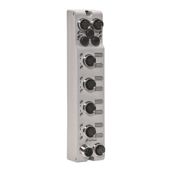
• download a free electronic version from the internet: http://literature.rockwellautomation.com • purchase a printed manual by contacting your local Allen-Bradley distributor or Rockwell Automation representative About the Module The ArmorBlock I/O 8 Channel IO-Link Master Module provides eight channels that can be individually configured as IO-Link master or as a standard digital I/O module. - Page 5 ArmorBlock I/O 8 Channel IO-Link Master Module Module Identification 45871 Description Description EtherNet/IP D-code M12 connector Auxiliary power indicator Function earth Micro-style power out EtherNet/IP D-code M12 connector Micro-style power in Link 2 status indicator Channel I/O or digital I/O status indicators Network status indicator Module status indicator Node address switches...
-
Page 6: Install The Module
6 ArmorBlock I/O 8 Channel IO-Link Master Module Install the Module To install the module: • Set the network address. • Mount the module. • Connect the I/O, Network and Auxiliary cables to the module. Set the Network Address The I/O block ships with the rotary switches set to 999 and DHCP enabled. To change the network address, you can do one of the following: •... -
Page 7: Mount The Module
ArmorBlock I/O 8 Channel IO-Link Master Module Set Network Address Example shows default node address set at 163. Note: You need to remove the protective switch dust caps before you can adjust the address settings. 44233 When the switches are set to a valid number, the I/O block’s IP address is 192.168.1.xxx (where xxx represents the number set on the switches). - Page 8 8 ArmorBlock I/O 8 Channel IO-Link Master Module Product Dimensions Refer to the mounting dimensions illustration to help you mount the module. Module Dimensions 37 (1.46) 25.6 16.2 (0.64) (1.01) 166.5 (6.56) 179 (7.05) 166.5 (6.56) 32 (1.26) Side Mounting 43.3 (1.70) Measurements are in millimeters (inches) 18 (0.71)
-
Page 9: Connect The I/O, Network And Auxiliary Cables To The Module
45768 Connect the I/O, Network and Auxiliary Cables to the Module The 1732E-8IOLM12R ArmorBlock EtherNet/IP module has a 5-pin micro-style I/O connectors. We provide caps to cover the unused connectors on your module. Connect the quick-disconnect cord sets you selected for your module to the appropriate ports. - Page 10 10 ArmorBlock I/O 8 Channel IO-Link Master Module EtherNet/IP Connector D-Code Micro Network Female Connector (View into connector 1) Pin 1 M12_Tx+ Pin 2 M12_Rx+ Pin 3 M12_Tx- Pin 4 M12_Rx- Pin 5 Connector shell shield GND 44808 (View into connector 2) Pin 1 M12_Rx+...
-
Page 11: Configure The Module
ArmorBlock I/O 8 Channel IO-Link Master Module Configure the Module Refer to the illustration for configuration operations. Configure Operations EtherNet/IP D-code EtherNet/IP D-code M12 connector M12 connector Network address switches M12 style I/O connectors Power connector Power connector 45871 Refer to On-Machine Connectivity Catalog, publication M117-CA001, for Rockwell Automation cable and cord set offerings or use the configuration tools available at www.ab.com/e-tools/. - Page 12 12 ArmorBlock I/O 8 Channel IO-Link Master Module Auxiliary Power Connectors Attach the micro-style 4-pin connector to the micro-style 4-pin receptacle as shown below. Auxiliary Power Micro-style 4-Pin Receptacles Male Input Female Output (View into receptacle) Pin 1 Auxiliary power+ Pin 2 Module/sensor power+...
-
Page 13: Interpret Led Indicators
ArmorBlock I/O 8 Channel IO-Link Master Module Interpret LED Indicators This module has the following indicators: • Module, Network, and Link status indicators for EtherNet/IP • Power status indicator • Individual channel status indicators for inputs and outputs Status Indicators Link 1 status indicator Link 2 status indicator Module status indicator... - Page 14 14 ArmorBlock I/O 8 Channel IO-Link Master Module Indicator Status for Module Indicator Status Description Module status Flashing red One or more recoverable minor faults detected. Possible minor faults indicated are: •The device is performing a firmware flash update. •The IO-Link stack is faulted. •IP Address switches do not match configuration in use •The device has completed a reset to factory default request due to the switches being set to 888 at power...
-
Page 15: Specifications
ArmorBlock I/O 8 Channel IO-Link Master Module Specifications General Specifications Attribute Value Number of inputs/outputs 8 Type 1 defined, sinking Communication rate, Ethernet 10/100 Mbps, Full or half-duplex 100 meter per segment Communication rate, IO-Link 4.8 kB; 38.4 kB; 230.4 kB Voltage, power, max 28.8V DC Voltage, power, min... - Page 16 16 ArmorBlock I/O 8 Channel IO-Link Master Module ArmorBlock I/O 8 Channel IO-Link Master Module – Standard Digital Input Attribute Value On-state voltage, min 15V DC On-state current, min 2.0 mA Off-state voltage, max 5V DC Off-state current, max 1.5 mA Input delay time Software configurable Sensor Source Voltage (SSV) voltage,...
- Page 17 ArmorBlock I/O 8 Channel IO-Link Master Module Environmental Specifications Attribute Value Temperature, operating IEC 60068-2-1 (Test Ad, Operating Cold), IEC 60068-2-2 (Test Bd, Operating Dry Heat), IEC 60068-2-14 (Test Nb, Operating Thermal Shock): -20…60 °C (-4…140 °F) Temperature, ambient 60 °C (140 °F) rating (UL) Temperature, nonoperating IEC 60068-2-1 (Test Ab, Unpackaged Nonoperating Cold),...
- Page 18 18 ArmorBlock I/O 8 Channel IO-Link Master Module Certifications Certification (when Value product is marked) c-UR-us UL Recognized Component, certified for US and Canada. See UL File E322657. EMC Directive 2014/30/EU Directive, compliant with: EN 61326-1; Meas./Control/Lab., Industrial Requirements EN 61000-6-2; Industrial Immunity EN 61000-6-4;...
- Page 19 ArmorBlock I/O 8 Channel IO-Link Master Module Notes: Publication 1732E-IN001A-EN-E - July 2016...
- Page 20 Rockwell Automation maintains current product environmental information on its website at http://www.rockwellautomation.com/rockwellautomation/about-us/sustainability-ethics/product-environmental-compliance.page. Allen-Bradley, Rockwell Automation, and ArmorBlock I/O are trademarks of Rockwell Automation, Inc. Trademarks not belonging to Rockwell Automation are property of their respective companies. Publication 1732E-IN001A-EN-E - July 2016...
Need help?
Do you have a question about the 1732E-8IOLM12R and is the answer not in the manual?
Questions and answers