
Related Manuals for Allen-Bradley ArmorBlock 1732E-16CFGM12M12LDR


Summary of Contents for Allen-Bradley ArmorBlock 1732E-16CFGM12M12LDR
- Page 1 User Manual Original Instructions ArmorBlock 16-Channel Configurable Digital Module Catalog Numbers 1732E-16CFGM12M12LDR, 1732E-16CFGM12P5DR...
-
Page 2: Important User Information
Important User Information Read this document and the documents listed in the additional resources section about installation, configuration, and operation of this equipment before you install, configure, operate, or maintain this product. Users are required to familiarize themselves with installation and wiring instructions in addition to requirements of all applicable codes, laws, and standards. -
Page 3: Table Of Contents
Table of Contents Important User Information ........2 Preface . - Page 4 Table of Contents Chapter 4 Diagnostic Properties Channel Error ..........35 Voltage Errors at M12 Slots (Sensor Short-circuit) .
-
Page 5: Preface
You can view or download publications at https://www.rockwellautomation.com/literature/. For publications specific to your module, search the catalog number of the module. To order paper copies of technical documentation, contact your local Allen-Bradley distributor or Rockwell Automation sales representative. Rockwell Automation Publication 1732E-UM001A-EN-P - December 2019... - Page 6 Preface Notes: Rockwell Automation Publication 1732E-UM001A-EN-P - December 2019...
-
Page 7: Module Information
Chapter Module Information Topic Page About the Module Module Features Module Overview Before You Begin About the Module The ArmorBlock 16-channel configurable digital module offers easy handling of I/O data in a higher-level bus system. It is suitable for use in machines and installations with moderate I/O concentration. -
Page 8: Module Overview
Chapter 1 Module Information • QuickConnect QuickConnect enables the module to start communicating quickly in an EtherNet/IP network through an accelerated startup process. Module Overview The ArmorBlock I/O 16-channel configurable digital module has 16 universal inputs/output. You can set individual channels as input only, output only, or input and output through the data direction setting in the Add-on Profile (AOP). -
Page 9: Configure And Startup
Chapter Configure and Startup Topic Page Download and Register EDS File Read the MAC Address Set the Network Parameters Configure the Module Configuration Parameters Configure in Logix Designer Edit the Module Configuration Common Pages Download and Register EDS An electronic data sheet (EDS) file is required to configure the module in the controller. -
Page 10: Read The Mac Address
Chapter 2 Configure and Startup 2. Click Next. 3. Select “Register an EDS file(s)” and click Next. 4. Click Browse and select the EDS file that you have downloaded. 5. Click Next to begin the EDS file registration. 6. Verify that the EDS Wizard successfully completed the registration. 7. -
Page 11: Set The Network Parameters
Configure and Startup Chapter 2 Set the Network Three rotary encoder switches on the front of the module enable you to set the operating mode for using or maintaining network parameters such as IP address, Parameters subnet mask, and gateway address. You can assign a static IP address to the module by using the rotary switches to set the last octet. -
Page 12: Configure The Module
Chapter 2 Configure and Startup Configure the Module The module supports Implicit Messaging and Explicit Messaging for EtherNet/IP communication. Use Implicit Messaging to transfer I/O process data cyclically through assembly objects and an existing connection. Use Explicit Messaging to transfer data with low priority, non time-critical, and configuration and through acyclical messages. -
Page 13: Output Fault Delay Configuration
Configure and Startup Chapter 2 Output Fault Delay Configuration These parameters are used when the module is configured with digital outputs. The configuration can be used to set a delay time (Output Fault Delay) that defines the monitoring procedure for the individual digital output for each channel. -
Page 14: Configure General Parameters
Chapter 2 Configure and Startup ATTENTION: When QuickConnect is enabled, you must notify the module before you switch the module ON (inhibit instruction) or OFF (uninhibit instruction). A hard disconnect during operation is not permitted. See the EtherNet/IP QuickConnect Application Technique, publication ENET-AT001, for more information. -
Page 15: Configure Process Data Direction
Configure and Startup Chapter 2 Configure Process Data Direction The data direction can be determined for each channel depending on the I/O mapping. Each of the 16 configurable channels can be configured as an input and output, as a pure input, or as a pure output. The following table describes the different process data direction. -
Page 16: Initial Settings Of The Connection Parameters
Chapter 2 Configure and Startup 13. Configure the module and download the parameters to the controller. In the Controller Organizer, you can view the connection data (extension: C), the input data (extension: I), and the output data (extension: O) of the configuration for the module. -
Page 17: General Page
Table 9 - General Parameters Parameter Definition Type Type of module Vendor Rockwell Automation/Allen-Bradley Name Enter a name for the module Description Enter an optional description for the module Module Definition Displays the module definition. For more information on how to configure... - Page 18 Chapter 2 Configure and Startup Module Definition Dialog To configure the Module Definition parameters, click Change on the General page of the New Module/Module Properties window. Figure 3 - Example of Module Definition Dialog Table 10 - Module Definition Parameters Parameter Definition Series...
-
Page 19: Connection Page
Configure and Startup Chapter 2 Connection Page Use the Connection page to configure the type of connection and behavior for the module. Figure 4 - Example of Connection Page Table 11 - Connection Parameters Parameter Definition Name Displays the type of connection Requested Packet Interval (RPI) (ms) Set the RPI rate. - Page 20 Chapter 2 Configure and Startup You set the RPI value during initial module configuration and can adjust it as necessary after module operation has begun. Valid RPI values are 1…750 ms. IMPORTANT If you change the RPI while the project is online, the connection to the module is closed and reopened in one of the following ways: •...
-
Page 21: Quick Connect Page
Configure and Startup Chapter 2 Quick Connect Page Quick Connect can help to reduce connection times if the module if used in a system where it has to be connected and disconnected as part of normal operation. Figure 5 - Example of Quick Connect Page Table 12 - Quick Connect Parameters Parameter Definition... -
Page 22: Module Info Page
This page displays information about the identity of your module and its fault status. Figure 6 - Example of Module Info Page Table 13 - Module Info Parameters Parameter Definition Identification Vendor Rockwell Automation/Allen-Bradley Product Type Module type Product Code Catalog number of the module Revision Firmware revision of module Serial Number... -
Page 23: Fault/Program Action Page
Configure and Startup Chapter 2 Table 13 - Module Info Parameters Parameter Definition Controls Refresh Refresh the data on the page Reset Module Reset the module to factory settings Fault/Program Action Page Configure the output state value for each individual channel of your module when the controller’s mode changes to fault or program. -
Page 24: Configuration Page
Chapter 2 Configure and Startup Configuration Page Configure the Fault Delay and Data Direction for each individual channel of your module. Figure 8 - Example of Configuration Page Table 15 - Configuration Parameters Parameter Definition Fault Delay Set the fault delay from 0…255 ms. Default is 80 ms. Data Direction Set whether the direction of data is input only, output only, or both input and output. -
Page 25: Internet Protocol Page
Configure and Startup Chapter 2 Internet Protocol Page Configure the IP settings for your module. IP settings can be set manually, configured automatically by using a DHCP server, or set using the rotary address switches on the module. The following settings are used if you selected to configure the IP settings manually. -
Page 26: Port Configuration Page
Chapter 2 Configure and Startup Port Configuration Page Configure settings for each individual port available on your module. Figure 10 - Example of Port Configuration Page Table 17 - Port Configuration Parameters Parameter Definition Enable Select to enable the port. Link Status Displays the connection status of the port. -
Page 27: Network Page
Configure and Startup Chapter 2 Network Page View status information about the network that the module is connected to. Figure 11 - Example of Network Page Table 18 - Network Parameters Parameter Definition Network Mode Displays the currently selected network redundancy protocol. Network Topology Displays the currently selected network redundancy protocol. - Page 28 Chapter 2 Configure and Startup Notes: Rockwell Automation Publication 1732E-UM001A-EN-P - December 2019...
-
Page 29: Configure Module Using Generic Profile
Chapter Configure Module Using Generic Profile Topic Page Configure the Module as a Generic Device Process Data for the Module Description of Process Data Terms Tag Name Conventions This chapter describes how to assign process data from the controller to the I/O channels of your module. -
Page 30: Configure The Module As A Generic Device
Chapter 3 Configure Module Using Generic Profile Configure the Module as a To configure the module as a generic device, follow these steps. Generic Device 1. Add the module as a generic Ethernet module. 2. Set valid configuration data for the I/O mapping in byte[98]…byte[129]. Rockwell Automation Publication 1732E-UM001A-EN-P - December 2019... -
Page 31: Process Data For The Module
Configure Module Using Generic Profile Chapter 3 3. Download the configuration to the controller and go online. Process Data for the Output Data Module 16-bit output data, default I/O mapping, assembly Instance 100. Output Bit 7 Bit 6 Bit 5 Bit 4 Bit 3 Bit 2... -
Page 32: Configuration Data
Chapter 3 Configure Module Using Generic Profile Configuration Data 16-bit configuration data with diagnostics and padding byte, default I/O mapping, assembly Instance 110. Parameter Datatype CfgSize DINT CfgIDNum DINT Pt00FaultDelay…Pt15FaultDelay Pt00Fault…Pt15Fault Pt00FaultValue…Pt015FaultValue Pt00FaultMode…Pt15FaultMode MiscSettings QuickConnectEn WebServerDisable OutputGroupPowerFaultEn OutputGroupFaultEn DOAutoRestartEn Pt00DataDirection…Pt15DataDirection Pt00IOMapping…Pt15IOMapping Description of Process Data The following table lists the definition for terms that are used in the process data... -
Page 33: Tag Name Conventions
Configure Module Using Generic Profile Chapter 3 Table 19 - Description of Terms in Process Data Tables Parameter Description OutputGroupPowerFaultEn Enables or disables the output group power fault reporting. 0 = Disable (default), 1 = Enable OutputGroupFaultEn Enables or disables the output group fault when actuator power supply is unavailable. 0 = Disable (default), 1 = Enable DOAutoRestartEn Enables or disables the digital out auto restart. - Page 34 Chapter 3 Configure Module Using Generic Profile Notes: Rockwell Automation Publication 1732E-UM001A-EN-P - December 2019...
-
Page 35: Channel Error
Chapter Diagnostic Properties Topic Page Channel Error Voltage Errors at M12 Slots (Sensor Short-circuit) Overload of Output Drivers Error in Actuator Power Supply Error in System/Sensor Power Supply The module provides advanced diagnostic messages to identify device errors during communication. The firmware of the module distinguishes between five different types of errors. -
Page 36: Voltage Errors At M12 Slots (Sensor Short-Circuit)
Chapter 4 Diagnostic Properties The filter is used to avoid premature error messages when a capacitive load is activated or an inductive load is deactivated, and during other voltage peaks when a status changes. When a channel is in the static state (permanently activated or deactivated) the controller uses a fixed specified duration of 100 ms for filtering the error message. -
Page 37: Error In System/Sensor Power Supply
Diagnostic Properties Chapter 4 ATTENTION: Every output channel that is active at the same time as the error occurs in supply voltage U is locked. This means that for correct operation, the output channel must be reset by the controller when the status of the supply voltage U has normalized again. - Page 38 Chapter 4 Diagnostic Properties Notes: Rockwell Automation Publication 1732E-UM001A-EN-P - December 2019...
-
Page 39: Status Indicator Overview
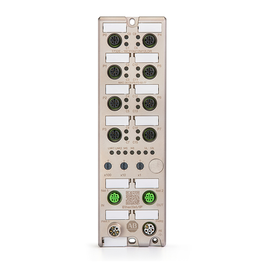
Appendix Interpret Status Indicators Topic Page Status Indicator Overview Status Indicator Descriptions Status Indicator Overview See the following figure to identify the location of the status indicators. Figure 12 - Status Indicators 1732E-16CFGM12M12LDR 1732E-16CFGM12P5DR MAC: XX-XX-XX-XX-XX-XX MAC: XX-XX-XX-XX-XX-XX Channel status indicators LNK1/LNK2 = EtherNet/IP connection status indicator MS = Module status indicator NS = Network status indicator... -
Page 40: Status Indicator Descriptions
Appendix A Interpret Status Indicators Status Indicator The following table describes the meaning of colors and flashes produced by the status indicators. Descriptions Table 21 - Status Indicators and Descriptions Status Indicator Color Description C0…C15 The channel is in the off state. Yellow for even channels;... - Page 42 Rockwell Automation maintains current product environmental information on its website at https://www.rockwellautomation.com/rockwellautomation/about-us/sustainability-ethics/product-environmental-compliance.page. Allen-Bradley, ArmorBlock, Logix 5000, Rockwell Automation, Rockwell Software, RSLogix 5000, Studio 5000, Studio 5000 Logix Designer, and TechConnect are trademarks of Rockwell Automation, Inc. CIP and EtherNet/IP are trademarks of ODVA, Inc.
Need help?
Do you have a question about the ArmorBlock 1732E-16CFGM12M12LDR and is the answer not in the manual?
Questions and answers