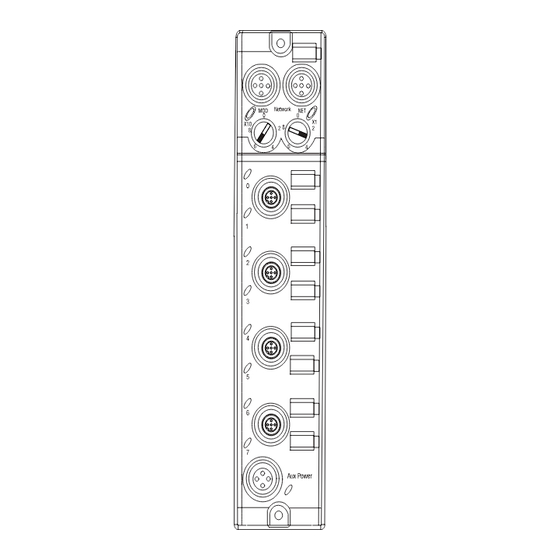
Allen-Bradley ArmorBlock 1732D A Series Installation Instructions Manual

Devicenet i/o

Advertisement

1
DeviceNet 1732 ArmorBlock I/O, Series A
(Cat. Nos. 1732D-IB8M12, -IB8M8, -OB8EM12, -OB8EM8,
-8CFGM12, -8CFGM8)
M12 Style
Connectors
The DeviceNet 1732D ArmorBlock™ I/O family consists of
stand-alone 24V dc I/O modules that communicate via the
DeviceNet network. The sealed IP67 housing of these modules
requires no enclosure (Note that environmental requirements other
than IP67 may require an additional appropriate enclosure.) I/O
connectors are sealed M8 (pico) or M12 (micro) styles while the
network and auxiliary power connectors are sealed M12 style.
Important User Information
Solid state equipment has operational characteristics differing from those of
electromechanical equipment. Safety Guidelines for the Application, Installation and
Maintenance of Solid State Controls (Publication SGI-1.1 available from your local
Rockwell Automation sales office or online at http://www.ab.com/manuals/gi)
describes some important differences between solid state equipment and hard-wired
electromechanical devices. Because of this difference, and also because of the wide
variety of uses for solid state equipment, all persons responsible for applying this
equipment must satisfy themselves that each intended application of this equipment
is acceptable.
In no event will Rockwell Automation, Inc. be responsible or liable for indirect or
consequential damages resulting from the use or application of this equipment.
The examples and diagrams in this manual are included solely for illustrative
purposes. Because of the many variables and requirements associated with any
particular installation, Rockwell Automation, Inc. cannot assume responsibility or
liability for actual use based on the examples and diagrams.
No patent liability is assumed by Rockwell Automation, Inc. with respect to use of
information, circuits, equipment, or software described in this manual.
Installation Instructions
M8 Style
Connectors
31433-M
Publication 1732D-IN001B-EN-E - May 2004

Advertisement

Table of Contents
loading

Summary of Contents for Allen-Bradley ArmorBlock 1732D A Series

  • Page 1 Installation Instructions DeviceNet 1732 ArmorBlock I/O, Series A (Cat. Nos. 1732D-IB8M12, -IB8M8, -OB8EM12, -OB8EM8, -8CFGM12, -8CFGM8) M12 Style M8 Style Connectors Connectors 31433-M The DeviceNet 1732D ArmorBlock™ I/O family consists of stand-alone 24V dc I/O modules that communicate via the DeviceNet...
  • Page 2 60529, as applicable, for explanations of the degrees of protection provided by different types of enclosure. Also, see the appropriate sections in this publication, as well as the Allen-Bradley publication 1770-4.1 ("Industrial Automation Wiring and Grounding Guidelines"), for additional installation requirements pertaining to this equipment.
  • Page 3: Preventing Electrostatic Discharge

    DeviceNet 1732 ArmorBlock I/O, Series A Preventing Electrostatic Discharge ATTENTION This equipment is sensitive to electrostatic discharge, which can cause internal damage and affect normal operation. Follow these guidelines when you handle this equipment: • Touch a grounded object to discharge potential static.
  • Page 4 DeviceNet 1732 ArmorBlock I/O, Series A The rotary switches are read periodically. If the switches have been changed since the last time they were read and they no longer match the on line address, a minor fault will occur, which is indicated by a flashing red MOD LED.
  • Page 5: Mount The Module

    DeviceNet 1732 ArmorBlock I/O, Series A Mount the Module Each module has two sets of mounting holes that are used to mount the module directly to a panel or machine. The module can be front or side mounted. Mounting holes accommodate #6 (M3) pan head screws.
  • Page 6 DeviceNet 1732 ArmorBlock I/O, Series A Mount the Module in High Vibration Areas If you will mount the module in an area that is subject to shock or vibration, we recommend that you use a flat and lock washer to mount the module.
  • Page 7 DeviceNet 1732 ArmorBlock I/O, Series A Pinout diagrams for the I/O connectors are shown below. 5-Pin Micro-Style (12mm) Female Connectors Input Connector Output Connector Cat. Nos. 1732D-IB8M12 Cat. Nos. 1732D-OB8EM12 (view into connector) (view into connector) 41452 Pin 1 Sensor Source Voltage Pin 1 Not Used Pin 2 Input B Pin 2 Output B...
  • Page 8 DeviceNet 1732 ArmorBlock I/O, Series A Refer to the illustration below for configuration operations. All I/O are 24V dc sink in/source out DeviceNet - 8 input - 8 output Node Address - 8 input or output points - any mix of 8 (e.g., 7 + 1; 3 + 5) 4-12mm or 8-8mm I/O Output short circuit protected Connectors...
  • Page 9 DeviceNet 1732 ArmorBlock I/O, Series A Attach DeviceNet Cables Attach the 5-pin (12mm) DeviceNet style connectors as shown below. DeviceNet Input Male Connector (view into connector) Pin 1 Drain Pin 2 V+ Pin 3 V- Pin 4 CAN_H 43584 Pin 5 CAN_L DeviceNet Output Female Connector (view into connector) Pin 1 Drain...
  • Page 10 DeviceNet 1732 ArmorBlock I/O, Series A Change-of-State - productions occur when an input changes or a fault condition occurs. If no input or fault condition change occurs within the expected packet rate, a heartbeat production occurs. This heartbeat production tells the scanner module that the I/O module is alive and ready to communicate.
  • Page 11: Troubleshoot With The Indicators

    DeviceNet 1732 ArmorBlock I/O, Series A Troubleshoot With This module has the following indicators: the Indicators • Network and Module status indicator for DeviceNet • Auxiliary Power indicator • Individual I/O status indicators for inputs and outputs M8 Style Connectors Module Indicator Network Indicator I/O Status Indicators...
  • Page 12 DeviceNet 1732 ArmorBlock I/O, Series A The following table describes network status indicators. Network Status Indicator - NS Module’s State Indicator Status Not Powered/ Device is not on-line: • The device has not completed the Not on line dup_MAC_id test yet. •...
  • Page 13: Specifications

    DeviceNet 1732 ArmorBlock I/O, Series A The following table describes the auxiliary power indicator. Auxiliary Power Indication Status None No Auxiliary Power Solid Green Auxiliary Power Present The following table describes individual I/O status indicators. I/O Status Indicators Function Point Indicator Condition Outputs None...
  • Page 14 DeviceNet 1732 ArmorBlock I/O, Series A DeviceNet 1732 ArmorBlock I/O Series A General Specifications Isolation Type tested to 500V ac for 60 seconds between auxiliary power and network (I/O to logic) Dimensions Inches (Millimeters) 1.9H x 2.7W x 6.9D (48H x 69W x 174D) Indicators Module Status - red/green Network Status - red/green...
  • Page 15 DeviceNet 1732 ArmorBlock I/O, Series A General Specifications (continued) Weight 0.448 lbs. (0.203 kg) Certifications: c-UL-us UL Listed Industrial Control Equipment, certified for US and Canada (when product is marked) European Union 89/336/EEC EMC Directive, compliant with: EN 61000-6-4; Industrial Emissions EN 50082-2;...
  • Page 16: Rockwell Automation Support

    Rockwell Automation Support Rockwell Automation provides technical information on the web to assist you in using our products. At http://support.rockwellautomation.com, you can find technical manuals, a knowledge base of FAQs, technical and application notes, sample code and links to software service packs, and a MySupport feature that you can customize to make the best use of these tools.

Table of Contents