Advertisement
Quick Links
Bulletin HY11-5715-590/UK
Installation Manual
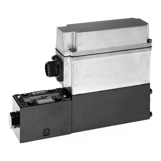
Series D1FH
Proportional DC Valve
Parker Hannifin GmbH
Hydraulic Controls Division
Gutenbergstr. 38
41564 Kaarst, Germany
Tel.:
+49-181 99 44 43 0
Fax:
+49-2131-513-230
E-mail: infohcd@parker.com
Copyright 2002, Parker Hannifin GmbH
Advertisement

Subscribe to Our Youtube Channel
Related Manuals for Parker D1FH series


Summary of Contents for Parker D1FH series
- Page 1 Bulletin HY11-5715-590/UK Installation Manual Series D1FH Proportional DC Valve Parker Hannifin GmbH Hydraulic Controls Division Gutenbergstr. 38 41564 Kaarst, Germany Tel.: +49-181 99 44 43 0 Fax: +49-2131-513-230 E-mail: infohcd@parker.com Copyright 2002, Parker Hannifin GmbH...
- Page 2 Installation Manual Series D1FH Note This document and other information from Parker Hannifin GmbH, its subsidiaries, sales offices and authorized distributors provide product or system options for further investigation by users having technical expertise. Before you select or use any product or system it is important...
- Page 3 Proportional DC Valve Installation Manual Series D1FH General Description The Parker D1FH valve is a high response pro- portional servo valve with an on-board drive amplifier. The D1FH incorporates the use of state- of-the art drive electronics with an LVDT for continuous monitoring of the spool position.
- Page 4 (different seal NG06 / 24VDC compound by CETOP 3 request) Flow [l/min] at ∆p = 35bar Code Spool type per metering edge E50B E50D E50H E50M E80B E80D E80H E80M IA D1FH UK A5.PM6.5 CM Parker Hannifin GmbH Hydraulic Controls Division...
-
Page 5: Technical Data
Protection class IP65, NEMA 4 Plug 6 + PE DIN 43563 EN 50081-2 EN 55011 EN 50082-2 ENV 50140 EN 61000-4-4 ENV 50204 EN 61000-4-5 EN 61000-4-2 EN 61000-4-6 IA D1FH UK A5.PM6.5 CM Parker Hannifin GmbH Hydraulic Controls Division... - Page 6 PWR supply COM. Board Setup Command input Jumpers select ±VDC JP2IN ±20mA JP1IN * P1 and P4 factory pre set - DO NOT ADJUST P2 Null P6 Driver Gain IA D1FH UK A5.PM6.5 CM Parker Hannifin GmbH Hydraulic Controls Division...
- Page 7 Once the system is operational, increase the NULL the valve. Refer to the Troubleshooting system gain and increase the system pressure. section. Functional Block Diagram, Version B * Factory adjustments - DO NOT ADJUST IA D1FH UK A5.PM6.5 CM Parker Hannifin GmbH Hydraulic Controls Division...
-
Page 8: Troubleshooting
The leakage rate through the fourth position blocked center spool (80 spool) will allow an unloaded single rod cylinder to extend. This occurs with any blocked center four-way valve. IA D1FH UK A5.PM6.5 CM Parker Hannifin GmbH Hydraulic Controls Division... - Page 9 The valve should be Subplate Specifications cycled periodically to prevent sticking. Subplate Port Size Location Max. Special Installations Pressure Consult your Parker representative for any appli- cation requiring the following: SPD23 3/8"NPTF Bottom 210 bar • Pressure above rated SPD2330 3/8"...
- Page 10 Proportional DC Valve Installation Manual Series D1FH Dimensions IA D1FH UK A5.PM6.5 CM Parker Hannifin GmbH Hydraulic Controls Division...
Need help?
Do you have a question about the D1FH series and is the answer not in the manual?
Questions and answers