Table of Contents
Advertisement
Quick Links
Bulletin MSG11-5715-688/UK
Operation Manual
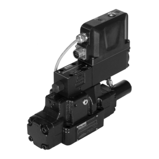
Series D*1FE
Pilot Operated
Design > 30
Proportional Directional
Control Valve
Parker Hannifin
Manufacturing Germany GmbH & Co. KG
Industrial Systems Division Europe
Gutenbergstr. 38
41564 Kaarst, Germany
Tel.: (+49) 181 99 44 43 0
E-mail: valvesisde@parker.com
Copyright © 2019, Parker Hannifin Corp.
Advertisement
Table of Contents

Related Manuals for Parker D41FE


Summary of Contents for Parker D41FE
- Page 1 Pilot Operated Design > 30 Proportional Directional Control Valve Parker Hannifin Manufacturing Germany GmbH & Co. KG Industrial Systems Division Europe Gutenbergstr. 38 41564 Kaarst, Germany Tel.: (+49) 181 99 44 43 0 E-mail: valvesisde@parker.com Copyright © 2019, Parker Hannifin Corp.
- Page 2 The user must analyze all aspects of the application, follow applicable industry standards, and follow the information concerning the product in the current product catalog and in any other materials provided from Parker or its subsidiaries or authorized distributors.
-
Page 3: Table Of Contents
Electrical Interfacing 5. Operating Instructions Preferred Hydraulic Initial State Solenoid Current Monitoring ProPxD parameterizing software Air Bleeding of Hydraulic System Filter Flushing 6. Trouble Shooting 7. Accessories / Spare Parts Accessories Spare Parts D_1FE 5715-688 UK CM 18.01.2019 Parker Hannifin Corporation... -
Page 4: Introduction
For details see For details see Catalogue HY11-3500UK Catalogue HY11-3500UK Code Inlest Drain Code Seals internal external external external internal internal for HFC fluid external internal For enlarged connections Ø 32 mm. D_1FE 5715-688 UK CM 18.01.2019 Parker Hannifin Corporation... -
Page 5: Characteristics Of Valve Driver
Name plate (main stage) Block Diagram of Integral Electronics Valve option code 0 (6+PE) Parker D*1FE proportional directional control valves Valve option code 5 (11+PE) have an integral electronics. Different sizes, as well as command signal options are available to achieve an optimal adaption for different applications. -
Page 6: Technical Data
Code 5 11 + PE acc. EN 175201-804 Wiring min. Code 0/7 7 x 1.0 AWG16 overall braid shield Code 5 8 x 1.0 AWG16 overall braid shield Wiring lenght max. [m] 50 D_1FE 5715-688 UK CM 18.01.2019 Parker Hannifin Corporation... -
Page 7: Safety Instructions
• operation outside the specifications Instructions applied on the valve, i.e. wiring dia- Do not disassemble the valve! In case of grams and name plates, must be observed and suspicion for a defect please contact Parker. maintained legibly. Storage Work at the Valve... -
Page 8: Mounting / Installation
O-rings. • Mounting bolts: oil-in-water emulsion D31FE: 4 pcs. M6x40 water-in-oil emulsion D41FE: 2 pcs. M6x55, 4 pcs. M10x60 unhydrous fluids (Phosphor-Ester) D81/91FE: 6 pcs. M12x75 D111FE: 6 pcs. M20x90 use property class 12.9, ISO 4762 For detailed information concerning pressure... -
Page 9: Electrical Connection
Cable length max. 50 m The connecting cable has to comply to the follow- ing specification: For cable lengths > 50 m consult Parker. Cable type control cable, flexible, The connection cable is coupled to the female 7 conductors, overall braid connector by crimp contacts. -
Page 10: Electrical Interfacing
Amp time lag. Non-observance of this instruc- use a low ohmic potential connection between tion may create irreparable damage of valve control unit and machine frame to prevent resp. incorporated system parts. earth loops (cross section AWG 6). D_1FE 5715-688 UK CM 18.01.2019 Parker Hannifin Corporation... - Page 11 Code 0, 6 + PE acc. EN 175201-804 Code 5, 11 + PE acc. EN 175201-804 Code 7, 6 + PE acc. EN 175201-804 + enable Do not connect with supply voltage zero. D_1FE 5715-688 UK CM 18.01.2019 Parker Hannifin Corporation...
-
Page 12: Operating Instructions
The output may drive a load of max. 5 mA. Exceeding of this limit leads to malfunction. Diagnostic signal 12,5 V in error case. Spool moves in a defined postion, please see order- ing code „spool position at power down“. D_1FE 5715-688 UK CM 18.01.2019 Parker Hannifin Corporation... -
Page 13: Solenoid Current Monitoring
Storage of complete parameter sets is possible as well as printout or record as a text file for further documentation. See www.parker.com/isde section “Support” for free software download. Please check periodical for updates. Hardware requirements •... - Page 14 Software Operating mode, a pass word is requested. The name is Brief instruction for first startup: “parker” and cannot be changed. Thus additionally to the button “Default” for loading of the default • Connect the valve electronic to the supply volt- parameters, the button “Send parameter”...
- Page 15 Closer information can be can be displayed via the ProPxD Parametrier software. Error code Error code Error description (additive) no errors over current cable break command signal cable break feedback signal undervoltage error bus communication error hardware failure D_1FE 5715-688 UK CM 18.01.2019 Parker Hannifin Corporation...
- Page 16 To turn on resp. off of the cable break detection of the command command signal at a selected command signal option of 4...20 mA. Adjustment of the MIN operating threshold. operating threshold To match the response sensitivity for the MIN-stroke step. D_1FE 5715-688 UK CM 18.01.2019 Parker Hannifin Corporation...
- Page 17 Adjustment of the fault response or report: 0 = no fault acknowledgment necessary 255 = fault acknowledgment necessary Errorhandling 768 = no fault acknowledgment + Fault report about diagnosis 1023 = fault acknowledgment + Fault report about diagnosis D_1FE 5715-688 UK CM 18.01.2019 Parker Hannifin Corporation...
-
Page 18: Air Bleeding Of Hydraulic System
Filter The function and lifetime of the valve are strongly affected by the cleanliness of the fluid. purity level class of 18/16/13 acc. ISO4406 is required. D_1FE 5715-688 UK CM 18.01.2019 Parker Hannifin Corporation... -
Page 19: Trouble Shooting
Code 5: 11-PE ordering code 5004711 Code 7: 6-PE ordering code 5004072 Spare Parts Seal kit NBR D31FE ordering code SK-D31FE D41FE ordering code SK-D41FE D81FE ordering code SK-D81FE D91FE ordering code SK-D91FE D111FE ordering code SK-D111FE D_1FE 5715-688 UK CM 18.01.2019...
Need help?
Do you have a question about the D41FE and is the answer not in the manual?
Questions and answers