Parker Series DFplus Operation Manual

Parker Series DFplus Operation Manual

Proportional directional
Hide thumbs Also See for Series DFplus:

Advertisement

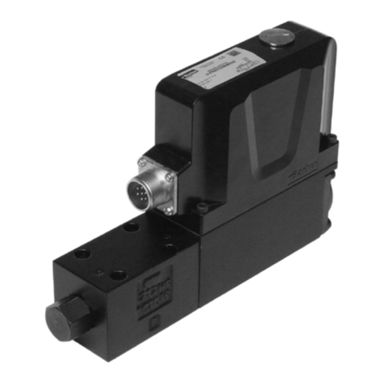
Bulletin HY11-5715-687/UK
Operation Manual
Series DFplus
Design > 30
Proportional Directional
Control Valve
Parker Hannifin
Manufacturing Germany GmbH & Co. KG
Hydraulic Controls Division Europe
Gutenbergstr. 38
41564 Kaarst, Germany
Tel.: (+49) 181 99 44 43 0
E-mail: valveshcd@parker.com
Copyright © 2016, Parker Hannifin Corp.

Advertisement

Table of Contents
loading

Summary of Contents for Parker Series DFplus

  • Page 1 Series DFplus Design > 30 Proportional Directional Control Valve Parker Hannifin Manufacturing Germany GmbH & Co. KG Hydraulic Controls Division Europe Gutenbergstr. 38 41564 Kaarst, Germany Tel.: (+49) 181 99 44 43 0 E-mail: valveshcd@parker.com Copyright © 2016, Parker Hannifin Corp.
  • Page 2 The user must analyze all aspects of the application, follow applicable industry standards, and follow the information concerning the product in the current product catalog and in any other materials provided from Parker or its subsidiaries or authorized distributors.
  • Page 3: Table Of Contents

    Prop. Directional Control Valve Operation Manual Series DFplus Contents Page Introduction Ordering Code D*FE Ordering Code D*FP Ordering Code D30FP Name Plate Characteristics of Valve Driver Block Diagram of Onboard Electronics Technical Data Safety Instructions Symbols Service Important Details Intended Usage...
  • Page 4: Introduction

    Prop. Directional Control Valve Operation Manual Series DFplus 1. Introduction D*FE Ordering Code Direct. Nominal Spool- Spool Y-port Seal Command- Elec- Spool/ Design control size type position (plugged) signal tronics body series (see (not re- valve on power option design...
  • Page 5: Ordering Code D*Fp

    Prop. Directional Control Valve Operation Manual Series DFplus D*FP Ordering Code Direct. Nominal Spool- Spool Y-port Seal Command- Elec- Spool/ Design control size type position (plugged) signal tronics sleeve series (see (not valve on power option design catalogue) required for...
  • Page 6: Ordering Code D30Fp

    Prop. Directional Control Valve Operation Manual Series DFplus D30FP Ordering Code Direct. Nominal Spool- Spool Seal Command- Elec- Spool/ Design Pilot con- control size type position signal tronics body series nection (see (not re- valve NG10 / on power option...
  • Page 7: Name Plate

    Prop. Directional Control Valve Operation Manual Series DFplus Name Plate Block Diagram of Onboard Electronics Code 0 (6+PE) Parametrizing interface Reference Command B, K: 0...±10 V µC 0...±20 mA 4...20 mA Diagnostic spool stroke 0...±10 V Reference hydr. spool symbol...
  • Page 8: Technical Data

    Prop. Directional Control Valve Operation Manual Series DFplus Technical Data General Model Proportional directional control valve, direct operated (D*FE, D*FP), pilot operated (D30FP) ® Drive -actuator Mounting interface NG06 (CETOP 03) / NG10 (CETOP 05) Installation position D*FE, D*FP: unrestricted; D30FP: horizontal mounting preferred...
  • Page 9: Safety Instructions

    Copyrights are reserved. Instructions with regard to the warranty Liability Instructions with regard to possible dam- Parker does not assume liability for damage due aging of the valve or linked system com- to the following failures: ponents •...
  • Page 10: Mounting / Installation

    VDMA-document 24317 as well D1FE/D1FP: 7.6 Nm as DIN 51524 & 51502. D3FE/D3FP/D30FP: 13.2 Nm Special gaskets may be available depending on the utilized fluid. In case of doubt please consult Parker. D_F_30 5715-687 UK.indd CM 03.08.17 Parker Hannifin Corporation Hydraulic Controls Division...
  • Page 11: Electrical Connection

    Outer dimension 8...12 mm Cable length max. 50 m For cable lengths > 50 m consult Parker. Do not disconnect cable socket under voltage! The connection cable is coupled to the female connector by solder joints. The shielding has to be assembled according the...
  • Page 12 Prop. Directional Control Valve Operation Manual Series DFplus Electrical Interfacing The backshell nut of the cable gland has to be tighten with a suitable tool. The target value for Supply Voltage the tightening torque is 4 Nm. Tighten the cap nut...
  • Page 13 Prop. Directional Control Valve Operation Manual Series DFplus Wiring Code 0, 6 + PE acc. EN 175201-804 Code 5, 11 + PE acc. EN 175201-804 Power supply Command B, K: 0...±10 V 0...±20 mA 5...30 V 4...20 mA Reference Enable...
  • Page 14 Prop. Directional Control Valve Operation Manual Series DFplus Enable input (only for Code 5 / 11+PE as well The option 4...20 mA uses the “3.6 mA“ as Code 7 / 6+PE) condition as breakdown-information. If the input signal line is interrupted, an evaluable A signal voltage enables the actuator drive of the failure information is available.
  • Page 15: Operating Instructions

    The PC software can be downloaded free of charge The cover plug has to be re-installed after at www.parker.com/euro_hcd – see page “Support” completion of the parametrizing work. or directly at www.parker.com/propxd. Please check periodical for updates.
  • Page 16 ProPxD icon for starting the program. changes shut the drive down! Software Operating To prevent an unauthorized access for the expert mode, a password is requested. The name is “parker” Brief instruction for first startup: and cannot be changed. Thus additionally to the •...
  • Page 17 Prop. Directional Control Valve Operation Manual Series DFplus LED flashing signals of the valve electronics enable valve OK: approx. 0.5 Hz (slowly, green) disable valve OK: approx. 1 Hz (fast, green) valve error: approx. 10 Hz (very fast, green) Closer information can be can be displayed via the ProPxD Parametrier software.
  • Page 18 Prop. Directional Control Valve Operation Manual Series DFplus Adjustment parameters The available parameters may be divided into S-parameters multiple groups and are characterized by different P-parameters letters: J-parameters Parameter overview for basic mode Parameter Range Default Parameter Description Unit Comment...
  • Page 19 Prop. Directional Control Valve Operation Manual Series DFplus Overview for additional expert mode parameter Parameter Range Default Parameter Description Unit Comment Setting from up to Min supply voltage supervision Relay time out off range 3200 1000 min supply voltage no fault acknowled- gement necessary;...
  • Page 20: Filter

    Prop. Directional Control Valve Operation Manual Series DFplus Error messages Malfunctions when using the ProPxD software program will be indicated via appropriate failure messages. Failure messages and corrective actions: Failure message Description/corrective action The Com Port is not available! Terminate the other program, or quit the message and select another RS232C port via the menu “Options >...
  • Page 21: Trouble Shooting

    Please direct technical product enquiries to: Accessories Parker Hannifin Manufacturing Germany GmbH & Co. KG The following accessories are available for the Hydraulic Controls Division Europe valve series DFplus: Gutenbergstr. 38 Bolt kit 41564 Kaarst, Germany D1FE/D1FP ordering code BK 375 Tel.: (+49) 181 99 44 43 0...

This manual is also suitable for:

DfeDfpD30fpParker dfplus series

Table of Contents