Table of Contents
Advertisement
Bulletin MSG11-5715-669/UK
Operation Manual
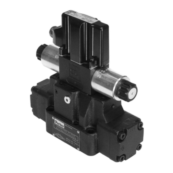
Series D*FB / D*1FB with
Integrated Electronics
D*FB Design ³ 12
D*1FB Design ³ 10
Proportional Directional
Control Valve
Parker Hannifin
Manufacturing Germany GmbH & Co. KG
Industrial Systems Division Europe
Gutenbergstr. 38
41564 Kaarst, Germany
Tel.: (+49) 181 99 44 43 0
E-mail: valvesisde@parker.com
Copyright © 2019, Parker Hannifin Corp.
Advertisement
Table of Contents

Related Manuals for Parker D31FB


Summarization of Contents
Introduction to Proportional Directional Control Valves
Series D*FB / D*1FB Overview
General introduction to the D*FB/D*1FB series with integrated electronics.
User Responsibility and Safety Warning
Product Usage Responsibility
Statement on user's responsibility for product selection and safe operation.
D*FB Series Introduction
Ordering Code Structure for D*FB
Details on how to construct the ordering code for D*FB valves.
Spool Position and Command Signals
Explanation of spool positions and available command signal options.
D*1FB Series Introduction
Ordering Code Structure for D*1FB
Details on constructing the ordering code for D*1FB valves.
Nominal Size and Valve Accessories
Information on nominal valve sizes and available accessories.
Valve Identification and Electronics
Name Plate Example
Example illustration of the valve's name plate with key information.
Integral Electronics Block Diagram
Schematic representation of the integral electronic driver's block diagram.
Technical Data
General Technical Specifications
General specifications including model, mounting, environment, and protection class.
Hydraulic and Electrical Specifications
Hydraulic parameters and electrical specifications for valve operation.
Scope, Safety, and Personnel
Scope of Supply and CE Marking
Details on delivery scope and CE mark compliance.
Personnel Requirements and Safety
Necessary personnel qualifications and initial safety instructions.
Product Usage and Risks
Usage Guidelines and Limits
Guidelines for product usage, operational limits, and contamination control.
Potential Risks and Precautions
Details on specific risks like temperature, power failure, and lightning effects.
Product Handling and Commissioning
Transport and Storage
Instructions for safe transport and proper storage conditions for the valve.
Commissioning Procedures
Steps and checks required for commissioning the valve in a system.
Mounting and Electrical Connections
Valve Mounting and Tightening
Details on valve mounting, torque specifications, and surface requirements.
Pressure Fluids and Electrical Connection
Information on compatible fluids and electrical connector/cable specifications.
W5 Connector and Grounding
W5 Connector Specification
Specifications for the 11+PE female connector for Code W5.
Cable Gland and Grounding
Instructions for tightening the cable gland and proper earth grounding connection.
Electrical Interfacing
Supply Voltage Requirements
Details on required supply voltage range, ripple, and surge protection.
Supply Voltage Wiring Diagrams
Wiring diagrams illustrating supply voltage connections for different codes.
Command Signal Input
Command Signal Input Details
Explanation of command signal input, its behavior, and signal quality.
Voltage Command Input Wiring
Wiring diagrams for voltage command inputs for F0/M0 codes.
Voltage Command Input Diagrams
F0/M0 Potentiometer Command Input
Wiring diagram for voltage command input with potentiometer for F0/M0.
W5 Command Input Diagrams
Wiring diagrams for voltage command input for W5 series valves.
Current Command Input Diagrams
G0 Current Command Input
Wiring diagram for current command input (0...+20/-20 mA) for G0.
S0 and W5 Current Command Input
Wiring diagrams for current command input (4...12/20 mA) for S0 and W5.
Recall Channels and Wiring
Internal Command Recall Channels
Explanation of recall channels for internal command presets and their options.
Recall Channels Wiring Diagram
Wiring diagram for recall channels for the W5 series.
ProPxD Software Configuration
ProPxD Software Overview
Introduction to the ProPxD software for valve parameter setting.
Parametering Cable and Hardware
Specifications for the parametering cable and required PC hardware.
Parametering Interface Connection
Instructions for connecting the parametering interface to the valve.
ProPxD Software Operation
Program Installation and Startup
Steps for installing the ProPxD software and initial startup procedures.
Software Operating Modes
Explanation of software operating modes: basic and expert.
Parameter Adjustment
Basic Mode Parameter Overview
Table of adjustable parameters and their ranges in basic mode.
Basic Parameter Descriptions
Detailed descriptions of basic mode parameters for valve adjustment.
Basic Parameter Details
Command Signal and Ramp Parameters
Detailed descriptions of command signal and ramp rate parameters.
Command Option and Cable Break Detection
Descriptions for command option, polarity, and cable break detection.
Expert Mode Parameters
Expert Mode Parameter Overview
Overview of parameters available in expert mode with their ranges.
Expert Parameter Descriptions
Detailed descriptions of expert mode parameters for advanced adjustment.
ProPxD Software Error Handling
Common Error Messages
List of common error messages encountered with the ProPxD software.
Corrective Actions for Errors
Corrective actions for resolving software error messages.
Operation, Maintenance, and Disposal
General Operation and Safety
Guidelines for safe operation and precautions during use.
Service, Maintenance, and System Bleeding
Procedures for service, maintenance, and air bleeding of the hydraulic system.
Decommissioning and Disposal
Steps for decommissioning the product and proper disposal methods.
Troubleshooting and Standards
Troubleshooting Approach
Systematic approach and initial checks for troubleshooting.
Troubleshooting Table
Table of common malfunctions and their corresponding corrective actions.
Applicable Standards and Rules
List of relevant industry standards and regulations for hydraulic systems.
Accessories and Spare Parts
Available Accessories
List of available accessories for D*FB/D*1FB series valves.
Spare Parts Information
Details on spare parts, including seal kits and bolt kits.
Need help?
Do you have a question about the D31FB and is the answer not in the manual?
Questions and answers