
Related Manuals for Ingersoll-Rand TS900 Series


Summary of Contents for Ingersoll-Rand TS900 Series
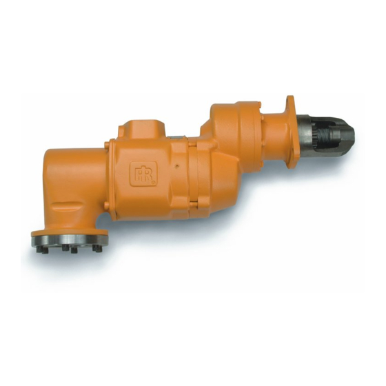
- Page 1 P7336 04575544 Edition 2 January 2014 Turbine Powered Starters Series TS900 Installation and Maintenance Information Save These Instructions...
-
Page 2: Product Safety Information
Product Safety Information Intended Use: These air starters are intended for use in starting reciprocating internal combustion engines. These starters are designed to be operated from a remote location after proper installation on the engine requiring starting. For additional information refer to Air Starters for Internal Combustion Engines Product Safety Information Manual Form 45558624. Manuals can be downloaded from ingersollrandproducts.com Model TS900 Turbine-Powered Starter Operating Guidelines WARNING... - Page 3 Orientation of the Starter Rotate the Drive Housing to the required position. Do not remove the Drive Housing from the Gear Case (3). Orientation refers to the rotational location of the lubrication ports Install the Cap Screws (35) and tighten to 28 ft.-lbs. (38 Nm) in the Drive Housing, the rotational location of the air (gas) inlet, torque.
- Page 4 Mounting Dimensions for Series TS900 Starters 86.00 [3.39”] (Dwg. TPE_1001) 04575544_ed2...
- Page 5 Piping Diagram for TS900 Turbine Installation (Dwg. TPE_1002) 04575544_ed2...
- Page 6 Piping Diagram for TS900 Multiple Starter Installation (Dwg. TPE_1003) 04575544_ed2...
- Page 7 TS900 Turbine Powered Starter - Section View (Dwg. TPE_1004) 04575544_ed2...
- Page 8 TS900 Turbine Powered Starter - Section View (Dwg. TPE_1005) 04575544_ed2...
- Page 9 TS900 Turbine Powered Starter - Exploded View (Dwg. TPE_1006) 04575544_ed2...
- Page 10 ST900 Turbine Powered Starter - Parts List Item Parts Decription Part Number Item Parts Decription Part Number Exhaust Kit ST700--350 Frame TS900--A108 Directional Housing Exhaust Cover ST700--350 Spacer (3) ST900--91 Exhaust Cover Seal Y327--162 Gear (3) ST900--10 Plug ROH--377 Bearing (3) ST900--24 Gear Case ST900--372...
-
Page 11: Motor Assembly Parts List
Motor Assembly Diagram (Dwg. TPD_1778) Motor Assembly Parts List Item Part Number Part Description Qty. Shaft Bearing End Plate O-ring Spacer End Plate Rotor Spacer Seal Spacer Screw Pinion Washer O-Ring Seal * These Parts only available as an Assembly. 04575544_ed2... -
Page 12: Maintenance
Maintenance WARNING Always wear eye protection when operating or performing any maintenance on this starter. Always turn off the air supply and disconnect the air supply hose before installing, removing or adjusting any accessory on this starter or before performing any maintenance on this starter. - Page 13 6. Grasp the rear of the Motor Assembly (12) and pull from the 2. Using two pry bars on opposite sides of the assembly, carefully rear of the Motor Housing. If the Motor Assembly is difficult to pry the two housings apart. remove, lightly, push the motor pinion which is in the front of the 3.
-
Page 14: Clutch Assembly
Clutch Assembly 10. Carefully set the Gear Case down over the Planet Frame Assembly and onto the Motor Housing. Rotate the Gear Case slightly NOTICE as needed to engage the Planet Gear Teeth into the internal The Clutch should be replaced after 1500 starts. Gear in the Gear Case. -
Page 15: Troubleshooting Guide
Troubleshooting Guide Trouble Probable Cause Solution No air supply Check for blockage or damage to air supply lines or tank. Inspect Motor Assembly and power train and repair power train Damaged Motor Assembly (12) or replace Motor Assembly if necessary. Motor will not run Remove Motor Assembly and/or piping and remove the Foreign material in Motor and/or piping... -
Page 16: Parts And Maintenance
Parts and Maintenance CAUTION The use of other than genuine Ingersoll Rand replacement parts may result in safety hazards, decreased motor performance, and increased maintenance, and may invalidate all warranties. Ingersoll Rand is not responsible for customer modification of Starters for applications on which Ingersoll Rand was not consulted. - Page 17 Notes:...
- Page 18 Notes:...
- Page 19 Notes:...
- Page 20 © 2014 Ingersoll Rand...
Need help?
Do you have a question about the TS900 Series and is the answer not in the manual?
Questions and answers