
Related Manuals for Ingersoll-Rand ST700 Series


Summary of Contents for Ingersoll-Rand ST700 Series
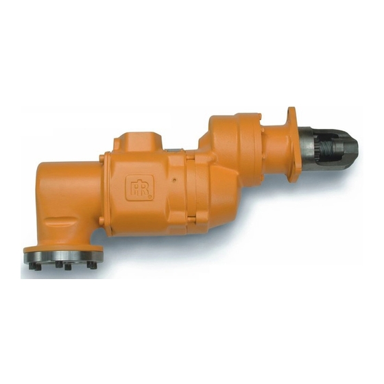
- Page 1 P6921 03537651 Edition 15 January 2014 Turbine Powered Starters Series ST700 Installation and Maintenance Information Installation and Maintenance Information 安装和维护信息 据付および保守の情報 Save These Instructions...
- Page 2 Product Safety Information Intended Use: These air starters are intended for use in starting reciprocating internal combustion engines. These starters are designed to be operated from a remote location after proper installation on the engine requiring starting. For additional information refer to Air Starters for Internal Combustion Engines Product Safety Information Manual Form 45558624. Manuals can be downloaded from ingersollrandproducts.com Placing the Starter in Service Installation...
- Page 3 When connecting the starter to a receiver tank that is already in 14. For Pre-Engaged Models, install a 1/4” hose line from the service, bleed off the air pressure in the tank prior to installing delivery side (marked “DEL”) of the starter Control Valve or the starter.
- Page 4 ST700 Inertia Mounting Dimensions (Dwg. TPA1276-4) 03537651_ed15...
- Page 5 Mounting Dimensions (Dwg. TPA1277-5) 03537651_ed15...
- Page 6 ST700 Pre-Engaged Mounting Dimensions (Dwg. TPA1278-4) 03537651_ed15...
- Page 7 Piping Diagrams Pre-Engaged System (Series ST700 Shown) Typical Vehicular Installation Starter Control Valve (2) Leads to Operators SMB - 618 (Brass) Solenoid Valve - 12 volt Starting Switch. 150BMP - 1051B #4 Hose (1/4”) “Optional Control Circuit Utilizing Electric Solenoid Control Valve and Panel Mounted Switch.
- Page 8 CONNECTIONS. SMB-441 FOR NATURAL GAS OPERATION, STARTER MAIN EXHUST MUST BE PIPED AWAY. INGERSOLL-RAND PART NUMBER TO PIPE THE DRIVE HOUSING VENT, REMOVE THE DRIVE HOUSING PLUG AND REPLACE IT WITH A SUITABLE TUBING LINE. THE TUBING MUST VENT AT A SAFE LOCATION AND MUST NOT BE INTERCONNECTED WITH ANY OTHER EXHAUST LINES WHICH MIGHT INTRODUCE A BACK PRESSURE ON THE DRIVE HOUSING VENT.
- Page 9 Piping Diagrams Pre-Engaged System (Series ST700 Shown) Typical Installation with Engine Prelube System when Supply Pressure is over Rated Starter Pressure Relief valve set at Oil Pressure Sensing Valve 15 P.S.I. above For gas operation, the Relay Valve 1½” regulator setting relief valve outlet must SRV150 #4 Hose (1/4”)
- Page 10 Piping Diagrams Typical Multiple Starter Installation #4 Hose (1/4”) #4 Hose (1/4”) (Dwg. TPA1284-4) 03537651_ed15...
- Page 11 Product Information Intended Use: Series ST700 Turbine Powered Starters are designed for air or gas operation in off-highway, marine and stationary applications. How to order a Starter - MODEL CODING - ST7 50 G B D I 03 R 31 - 0 N Supply Pinion Data Drive...
- Page 12 产品安全信息 用途: 此类空气启动器应用于往复式内燃机的启动。此类启动器应在正确安装到需要启动的内燃机上后,进行远程操作。 更多信息请参见内燃机空气启动器产品安全信息手册表 45558624。 手册可从 www.irtools.com 下载。 使起动器处于使用状态 安装 起动器的定向 建议起动器应该根据所需发动机的特殊装置或特殊设备进行正确 注 意 定向。 但是,如果起动器因安装而必须重新定向,可按照以下 步骤操作: 为获得最大性能,请在安装或操作 ST700 系列涡轮电力起动器 请参阅第 EN5、EN6 和 EN7 页的尺寸图示,另请注意,传动箱 (Series ST700 Turbine-Powered Starters) 之前阅读本手册。 可位于与齿轮箱相对的 16 个径向位置中的任一处,并且空气 进口阀可位于与传动箱相对的 4 个径向位置中的任一处。 一般信息 学习发动机安装要求,并确定与齿轮箱相对的传动箱的所需 定向。 如果传动箱必须重新定位,可卸下 8 个传动箱有头螺 强烈建议在受到振动的所有车载装置和固定发动机上,应该使...
- Page 13 发动机盘车 9. 要确定所需的 1-1/2” 进气软管的确切长度,可重负荷运行软 管设备或直径相同的某些其他挠性软管(从储气罐的主启动阀 有时,为了设置喷油器和/或定时,可能需要以此方式(所提供的 到发动机的起动器位置)。 活塞可在任何给定地点停止)发动机盘车。 这可通过 ST700 系列 10. 将 1-1/2”进气软管连接到主启动阀的出口侧,并使软管从机 涡轮起动器轻易完成。 架等穿过起动器处的最终位置。 卸下导向板固定螺丝 (5)、导向板回位弹簧 (4) 和防溅导向板 11. 在此,可在实际安装起动器之前或之后,确定将软管连接到起 (3)。 如果使用排出的废气,可拆卸管道以便可以使用外壳废气盖 动器是否可行或实用。在多数情况下,可能需要在安装之前将 中央的孔。 卸下 1/4” 管道塞子。 软管连接到起动器。 对于具有惯性传动装置的型号: 12. 如果可能,请使用优质粘性齿轮润滑油充分润滑环形齿轮上的 齿轮。这将有助于延长环形齿轮和起动器小齿轮的寿命。 手动安装小齿轮,并通过外壳盖中的孔插入 1/4” 六角扳手以 13. 将起动器各就其位,然后将其安装在飞轮壳上。 旋紧安装螺 在马达组件尾部安装六角传动凹槽。...
- Page 14 ST700 惯性装置尺寸 (图. TPA1276-4) 03537651_ed15...
- Page 15 安装尺寸 (图. TPA1277-5) 03537651_ed15...
- Page 16 ST700 预先安装的安装尺寸 (图. TPA1278-4) 03537651_ed15...
- Page 17 管道布置图 预啮合安装的系统(显示 ST700 系列) 典型的车载安装 起动器控制阀 (2) 连接到操作者 SMB - 618 (铜) 电磁阀 - 12 伏 起动开关的导线。 150BMP - 1051B #4 号软管 (1/4”) “可选控制电路利用 电磁控制阀和 安装在面板上的开关。 ” 空气压力表 #4 号软管 (1/4”) 150BMP - 1064L 来自干燥空气箱 JIC 37° 接头 1/4” N.P.T. 中的气源...
- Page 18 管道布置图 惯性啮合系统(显示 ST700 系列) 典型的车载安装 (2) 连接到操作者 起动器控制阀 起动开关的导线。 电磁阀 - 12 伏 SMB - 618 (铜) 150BMP - 1051B #4 号软管 (1/4”) 空气压力表 150BMP - 1064L “可选控制电路利用 电磁控制阀和 安装在面板上的开关。 ” JIC 37° 接头1/4” N.P.T. 来自干燥空气箱 SS350 - MC4 中的气源 单向阀...
- Page 19 管道布置图 预啮合安装的系统(显示 ST700 系列) 具有发动机预先润滑系统的典型安装时供应压力超过起动器压力的安装形势。 以超出减压阀 油压感应阀 15 P.S.I. 设置 主启动阀 1½” 对于气体操作, SRV150 #4 号软管 (1/4”) 必须从减压阀排放到安全地方 JIC 37° 接头 1/4” N.P.T. 高压 供应 JIC 37° 接头 SS350 - MC4 1½” N.P.T. JIC 37° 接头 1/4” N.P.T. SS350 - MC4 1½” 管道 空气压力表...
- Page 20 管道布置图 典型多起动器装置 #4 号软管 (1/4”) #4 号软管 (1/4”) (图. TPA1284-4) 03537651_ed15...
- Page 21 产品信息 用途: ST700 系列涡轮电力起动器是为非公路车辆、船舶和固定装置中的空气或天然气操作而设计。 如何订购起动器 - 型号编码 - ST7 50 G B D I 03 R 31 - 0 N 小齿轮数据 传动 最大供应压力 型号 传动箱 P.D. 基本型号 PSIG/Kpa * IR No. 轮齿编号 D.P. 百分比弧度 定向代码 ST750GBDI03R31 150/1034 20BM-299-1 12/12 2.00” 20°...
- Page 22 製品に関する安全性 製品に関する安全性 これらのエアスターターは、 往復内燃機関の始動に使用するこ とを目的と しています。 これらのエアスターターは、 始動させる必要のある往復 内燃機関に正しく取り付けた後、 離れた場所から操作するように設計されています。 詳細は、 「 内燃機関用エアスターター製品安全情報説明書 45558624 」 を参照してく ださい。 www.irools.com から説明書をダウンロードすることができます。 始動装置の供用 再組付け 8. システムの緊急再加圧用の 「友好的握手」 の再組付けを推奨し ます。 「友好的握手」 を清浄に、 塵埃の無いように保ち、 損傷がら 保護するために、 パイプ栓によって閉められた二番目の 「友好的 握手」 をこれに合わせて取り付けるかまたは 「友好的握手」 保護 ブラケッ トを使用することが可能です。 最高の性能を得るために、 シリーズ ST700 タービン動力始動装置の 9.
- Page 23 始動装置を既に使用中の空気受けタンクに接続するときは、 始 15. 1/4 インチ ホースラインを [始動装置ドライブ収納部] 上の 「 動装置を取り付ける前に、 タンク内の空気圧を徐々に減らして OUT」 出口から [始動装置リレーバルブ] または [ソレノイドバル 無く します。 ブ] の小管のタップ付きの部分に取り付けます。 16. 排気が導出される場合、 [収納部排気カバー] の背後に配置され ている標準 [スプラッシュディフレクタ] を取り外し、 始動装置に 付属してきた1/4 インチ N.P.T. パイプ栓を備えた [組立品] に交 空気圧をバルブまたはコッ クを通して徐々に減ら して無く します。 タ 換します。 ンク内にまだ圧力がある間にタンクから栓を抜く...
- Page 24 ST700 慣性取り付け寸法 (図面. TPA1276-4) 03537651_ed15...
- Page 25 取り付け寸法 (図面. TPA1277-5) 03537651_ed15...
- Page 26 ST700 事前取り付け済み品の取り付け寸法 (図面. TPA1278-4) 03537651_ed15...
- Page 27 配管図 事前取り付け済みシステム (表示されているシリーズ ST700) SMB - 618 ( 150BMP - 1051B (1/4 “ ” (1/4 150BMP - 1064L JIC 37° 1/4” N.P.T. SS350 - MC4 JIC 37° 150BMP - 1056 1½” N.P.T. 1½” 1 ½ N.P.T. 1/8” N.P.T. 1½ ST700 - K166 1½...
- Page 28 配管図 慣性タイプ システム (表示されているシリーズ ST700) SMB - 618 ( 150BMP - 1051B (1/4 150BMP - 1064L “ ” JIC 37° 1/4” N.P.T. SS350 - MC4 JIC 37° 1½” N.P.T. 1½” ST700 - K166 1 ½ N.P.T. 1½ SRV150 N.P.T 1½ 150BMP - 1067 NP.T.
- Page 29 配管図 事前取り付け済みシステム (表示されているシリーズ ST700) 供給力が定格始動置力を超えたときのエンジン事前潤滑システムとの典型的設定 レギュレータ設定より 油出バルブ 15 P.S.I. 高く ガス運?の場合、 1½ インチ #4 ホース 設定された開放バルブ 開放バルブ排口は、 リレー バルブ (1/4 インチ) 配管によって安全な位置に SRV150 離れさせる必要があります。 JIC 37° アダプタ 1/4” N.P.T. JIC 37° アダプタ SS350 - MC4 1½” N.P.T. JIC 37° アダプタ 1/4” N.P.T. SS350 - MC4 高?供給...
- Page 30 配管図 典型的な複式始動装置の再組付け (1/4 (1/4 (図面. TPA1284-4) 03537651_ed15...
- Page 31 製品情報 製品の用途 : タービンを動力とするシリーズ ST700 始動装置は、 オフ ハイウェイ、 海洋および固定の各用途に於いて空気またはガスで運転するように設 計されています。 始動装置の発注方法 ST7 50 G B D I 03 R 31 - 0 N P.D. PSIG/Kpa IR No. D.P. Max.* ST750GBDI03R31 20BM-299-1 12/12 2.00” 20° 150/1034 ST750GBDI03L32 20BM-299-3 12/12 2.00” 20° 150/1034 : B=2.18-1 20BM-299-1...
- Page 32 Parts Information Cross Section Diagram, ST700 Turbine Powered Starter (Dwg. TPA1275-2) 03537651_ed15...
- Page 33 Exploded Diagram, ST750 Turbine Powered Starter (Inertia) (Dwg. TPA1272-2) 03537651_ed15...
- Page 34 Parts List, ST750 Turbine Powered Starter (Inertia) Item Part Description Part Number Item Part Description Part Number Housing Exhaust Cover Assembly ST700-A562 † 31 Rear Drive Gear Bearing SS800-359 Housing Exhaust Cover ST700-562 Gear Case Cover SS810-678 Exhaust Cover Seal Y330-257 †...
- Page 35 Exploded Diagram, Series ST700 Turbine Starter (Pre-Engaged) (Dwg. TPA1273-5) 03537651_ed15...
- Page 36 Parts List, Series ST700 Turbine Starter (Pre-Engaged) Item Part Description Part Number Item Part Description Part Number Housing Exhaust Cover Assembly ST700-A562 Intermediate Pinion Retaining Screw SS800-732 Housing Exhaust Cover ST700-562 Gear Case Exhaust Cover Seal Y330-257 for Models ST750GDDP09R51, Exhaust Cover Plug ST700-K37 ST750GDDP09L52,...
- Page 37 Parts List, Series ST700 Turbine Starter (Pre-Engaged) - Continued Item Part Description Part Number Item Part Description Part Number Clutch Spring Cup Retainer Drive Pinion Retaining Screw SS800-366 Clutch Spring Cup SS800-367 for Models ST750GBDP03R31, Clutch Spring SS800-583 ST750GCDP03R25, SS800R-394 Clutch Jaw Kit ST799GBDP03R31 and for Models ST750GBDP03R31,...
- Page 38 Parts List, Series ST700 Turbine Starter (Pre-Engaged) - Kits Item Part Description Part Number Item Part Description Part Number Flange Mounting Hardware Kit Tune-up Kit (for ST799 models with right (includes O-ring, Mounting Bolts and hand rotation) includes 12, 14, 16, 16A, ST750-K167 ST799R-TK4 Lock Washers)
- Page 39 ST700K-350 Exhaust Kit (Available at extra cost) Item Description Part Number Exhaust Kit ST700K-350 Directional Housing Exhaust ST700-350 Cover Capscrew (6) ST700-703 Lockwasher (6) 845-58 Exhaust Adapter ST700-351 Exhaust Adapter Seal Y327-46 Exhaust Cover Seal Y330-257 Weld Sleeve ST700-352 Plug R0H-377 * Not illustrated.
- Page 40 Maintenance WARNING Always wear eye protection when operating or performing any maintenance on this starter. Always turn off the air or gas supply and disconnect the air or gas supply hose before installing, removing or adjusting any accessory on this starter or before performing any maintenance on this starter.
- Page 41 5. Tap the Motor Housing with a plastic hammer to dislodge it from the Intermediate Gear Case (13). Refer to Dwg. TPD1162. Plastic Hammer Loosen 1-1/2 Turns Only. Do not remove. (Dwg. TPD1162) (Dwg. TPD1169) 6. Grasp the rear of the Motor Assembly (12) and pull it from the 10.
- Page 42 Disassembly of the Drive Housing 6. Using an impact wrench with a 5/16” (8 mm) x 8” (203 mm) long hex inserted into the end of the Drive Shaft, unscrew the Drive Inertia Models: Gear Screw (34). 7. Unscrew and remove the Drive Housing Cap Screws (38) and Lock Remove the eight Drive Housing Cap Screws (40) and Lock Washers (39).
- Page 43 25. Pull the Drive Gear (29) out of the Gear Case. NOTICE Do not disassemble the Drive Gear and Clutch parts of Series ST700 Turbine-Powered Starters. If the Drive Shaft is defective, install a new or factory-rebuilt unit. 26. Using retaining ring pliers, remove the Drive Gear Shaft Bearing Retainer (33).
- Page 44 14. Insert the Clutch Spring Cup (50) into the Drive Shaft. 15. Press the inserted parts into the Drive Shaft, and install the Clutch Spring Cup Retainer (49). NOTICE If it is necessary to replace the Drive Housing (40) and drive components, make sure that the Piston Seal (part number SS800- 272) has been removed from the rear of the new Piston (54).
- Page 45 33. Lubricate using Ingersoll Rand No. 11 Grease and slide the NOTICE Pinion Spring (65) and the Pinion Spring Sleeve (64) over the Pinion end of the Drive Shaft. Do not move or turn over the Planet Gear Frame until steps 6 34.
- Page 46 14. Align the punch marks on the Motor Housing with the punch marks on the Intermediate Gear Case and using a plastic hammer, tap the Motor Housing until it seats on the rear of the Intermediate Gear Case. Refer to Dwg. TPD1163. (Dwg.
- Page 47 19. Install the bottom Housing Plug (10) and the Housing Plug Inlet Boss (11). Put the Starter on its side with the side plug hole upward. Add 175 ml (approximately 1/3 pint) of Dexron® II Automatic Transmission Fluid through the side plug hole in the Motor Housing (8).
- Page 48 Troubleshooting Guide Trouble Probable Cause Solution Motor will not run No air supply Check for blockage or damage to air supply lines or tank. Damaged Motor Assembly Inspect Motor Assembly and power train and repair or replace if necessary. Foreign material in Motor and/or piping Remove Motor Assembly and/or piping and remove the blockage Blocked exhaust system...
- Page 49 Parts and Maintenance CAUTION The use of other than genuine Ingersoll Rand replacement parts may result in safety hazards, decreased motor performance, and increased maintenance, and may invalidate all warranties. Ingersoll Rand is not responsible for customer modification of Starters for applications on which Ingersoll Rand was not consulted. Repairs should be made only by authorized trained personnel.
- Page 50 Notes:...
- Page 51 Notes:...
- Page 52 ingersollrandproducts.com © 2014 Ingersoll Rand...
Need help?
Do you have a question about the ST700 Series and is the answer not in the manual?
Questions and answers