Table of Contents
Advertisement
Quick Links
User Guide
Variable Refrigerant Flow (VRF) System
Wired Remote Controller
Model Numbers:
Only qualified personnel should install and service the equipment. The
installation, starting up, and servicing of heating, ventilating, and air-
conditioning equipment can be hazardous and requires specific knowledge and
training. Improperly installed, adjusted or altered equipment by an unqualified
person could result in death or serious injury. When working on the equipment,
observe all precautions in the literature and on the tags, stickers, and labels that
are attached to the equipment.
September 2016
TVCTRLTWRWD02T
TVCTRLTWRWD02A
SAFETY WARNING
VRF-SVU41C-EN
Advertisement
Table of Contents

Related Manuals for Ingersoll-Rand TVCTRLTWRWD02T


Summary of Contents for Ingersoll-Rand TVCTRLTWRWD02T
- Page 1 User Guide Variable Refrigerant Flow (VRF) System Wired Remote Controller Model Numbers: TVCTRLTWRWD02T TVCTRLTWRWD02A SAFETY WARNING Only qualified personnel should install and service the equipment. The installation, starting up, and servicing of heating, ventilating, and air- conditioning equipment can be hazardous and requires specific knowledge and training.
- Page 2 Introduction Read this manual thoroughly before operating or servicing this unit. Warnings, Cautions, and Notices Safety advisories appear throughout this manual as required.Your personal safety and the proper operation of this machine depend upon the strict observance of these precautions. The three types of advisories are defined as follows: Indicates a potentially hazardous situation which, if not avoided, could result WARNING...
-
Page 3: Table Of Contents
WARNING Personal Protective Equipment (PPE) Required! Failure to wear proper PPE for the job being undertaken could result in death or serious injury. Technicians, in order to protect themselves from potential electrical, mechanical, and chemical hazards, MUST follow precautions in this manual and on the tags, stickers, and labels, as well as the instructions below: •... -
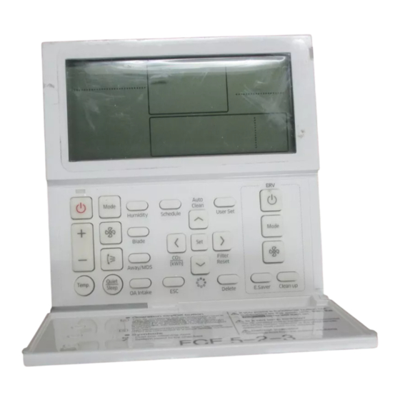
Page 4: Display And Buttons
Display and Buttons Changing a User Setting (Example) ......20 Display and Buttons Figure 1. Display elements and cover buttons 11 12 13 14 LED indicator... - Page 5 Display and Buttons Note: You can turn the unit On/Off or set the desired temperature without opening the cover of the wired remote controller. Table 1. User interface elements classified and described Classification Indicator Description Displays unit operation Displays quiet/sleep operation Unit Displays discharge temperature control functions...
- Page 6 Display and Buttons Table 1. User interface elements classified and described (continued) Classification Indicator Description Displays invalid operation/central control/filter cleaning (filter cleaning period) Displays check/partial locking/full locking Displays away/motion detector sensor/ outdoor air supply intake/humidifying/ external interconnection control/range hood Common functions Some of these features are not Note:...
- Page 7 Display and Buttons Figure 2. Buttons Quiet/Sleep VRF-SVU41C-EN © 2016 Ingersoll Rand All Rights Reserved...
- Page 8 Display and Buttons Table 2. Buttons classified and described Classification Button Function Operation Turns the unit operation On/Off On/Off Mode Selects the desired unit operation Temperature Sets the desired temperature setpoint setpoint Fan speed Changes the unit fan speed Air flow Changes the air flow direction Unit functions Room...
- Page 9 Display and Buttons Table 2. Buttons classified and described (continued) Classification Button Function Schedule Selects the schedule setting function User Set Selects the detailed setting functions Navigational Moves between items or changes the item value Saves new settings Returns to general mode from schedule and detailed setting screens Special functions...
-
Page 10: Operation
Operation Operation Turning On/Off the Indoor Unit Press the Power button [ ] to turn the unit on/off. Changing Operating Modes Press the Mode button [ ] to select the desired operation. Note: The system may not respond to the remote control signal if the building is currently operating in a mode that is in conflict with the mode you are requesting (for example, a request for cooling when the building is currently heating, or vice versa). -
Page 11: Heat
Operation Heat While the unit is in Heat mode, be aware of the following: • There may be a delay before the fan begins running to avoid generating a cold breeze. • The defrost indicator ( ) will appear when frost is being removed from the outdoor unit. -
Page 12: Changing Settings And Functions
Operation Changing Settings and Functions Temperature Setpoint Press the button to change the desired temperature setpoint for the room. +/— Note: The temperature setpoint cannot be adjusted when the unit is operating in Fan mode. Auto Adjust the desired temperature by 1ºF within the range of 65-86ºF Cool Adjust the desired temperature by 1ºF within the range of 65-86ºF Adjust the desired temperature by 1ºF within the range of 65-86ºF... -
Page 13: Quiet/Sleep
Operation Quiet/Sleep The Quiet function reduces operating noise.The Sleep function automatically turns the unit off after six hours of operation. Press the Quiet/Sleep button [ ] until the desired operation appears on the display: Quiet, Sleep, or both Quiet and Sleep. Refer to the following list for the functions that are available in the various operating modes: If the unit supports both Quiet and Sleep functions:... -
Page 14: Away Function/Motion Detection Sensor
Operation Away Function/Motion Detection Sensor The Away function automatically turns off the power to the unit after running the energy savings operations for a designated period of time. Note: The Away function is available only for the global duct model. The Motion Detection Sensor automatically turns off the power to the unit when the room is unoccupied. - Page 15 Operation 3. Press the up/down arrow buttons to select the day. An outline will appear around the selected day. In the example below, Saturday has been selected. Note: If a selected event is to apply to more than one day, select other days of the week by the same method.
- Page 16 Operation 12. Press > to advance to the operating mode section.The Auto mode icon will flash. 13. Press the up/down arrow to select an operating mode (Auto, Cool, Dry, Fan, or Heat). 14. Depending on the unit model, Auto and Heat may not be available as mode options. 15.
-
Page 17: Scheduling Holidays
Operation When a day with a scheduled event is selected, the event is represented by a number on the display.The example below shows that Monday has three events. When an event is selected, an outline appears around the number.The example below shows “3”... -
Page 18: User Settings
Operation User Settings This section discusses user settings that are available in the wired remote controller. SEG Used Digits Main menu Sub-menu 1 2 3 4 Table 3. Wired Remote Controller User Settings Main Sub- menu menu Functions Digit Default Range Unit Auto stop time setting/checking... -
Page 19: User Settings Procedure
Operation Main Sub- menu menu Functions Digit Default Range Unit Use of summer time Summer 0-not used, 1-use (Y/N) time use and setting Summer time 0-Weekly, 1-daily methods application method 1-12 month/ Summer time use (weekly) 1,2/4 03/F 1-4,F (last Start (? month, ? th Sunday) week)th week 1-12 month/... - Page 20 Changing a User Setting (Example) This example demonstrates how to use the wired remote control to set the current time: Press the User Set button.The Main Menu appears. 2. Press the up/down button to select number 4, which sets the current time. 3.
Need help?
Do you have a question about the TVCTRLTWRWD02T and is the answer not in the manual?
Questions and answers