Table of Contents
Advertisement
Quick Links
Close
Go Back
Introduction
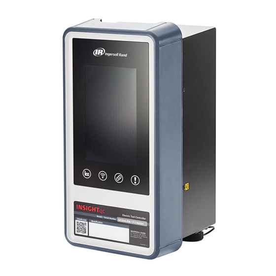
INSIGHTqc Precision Fastening Controllers are designed to control the fastening operation of
threaded fasteners and communicate with external systems for data collection and control.
About this Manual
This manual provides detailed instructions on how to use the INSIGHTqc Precision Fastening
Controllers.
Browser Settings
JavaScript and pop-ups must be enabled to view INSIGHTqc WebHelp contents.
Compatibility
Device
Desktop
Desktop
Desktop
Ipad (IOS
8.1)
Mobile
(Android
OS V5.1.1)
Browser
Version
Google
35 or
Chrome
later
Mozilla
37 or
Firefox
later
Internet
11 or
Explorer
later
Google
47 or
Chrome
later
Mozilla
42 or
Firefox
later
Go to top
Close
Advertisement
Table of Contents

Related Manuals for Ingersoll-Rand INSIGHTqc


Summary of Contents for Ingersoll-Rand INSIGHTqc
- Page 1 INSIGHTqc Precision Fastening Controllers are designed to control the fastening operation of threaded fasteners and communicate with external systems for data collection and control. About this Manual This manual provides detailed instructions on how to use the INSIGHTqc Precision Fastening Controllers. Browser Settings JavaScript and pop-ups must be enabled to view INSIGHTqc WebHelp contents.
- Page 2 Close Go Back Home This screen gives an interface for the user to monitor Cycle Status, Batch Count, Angle or Torque values achieved against the defined limits, System Alarms, Trace, Cycle Results, and connection status of any external devices connected to the fastening controller.
- Page 3 Figure A: Home Screen Icons displayed at top left corner of the home screen are described as follows: Icon Description Select to view menu options. Green icon indicates that the tool is connected. Red icon indicates that the tool is not connected.
- Page 4 Cycle Status Parameters displayed on the cycle status area are described as follows: Parameter Description Indicates pass or fail status of the Cycle Status last tightening. Specifies the total number of fasteners to be fastened in a group. Total Batch Count NOTE : Graphical representation of Batch count and the numerical...
- Page 5 NOTE : It triggers when angle achieved is less than the set limit. NOTE : For a quick identification of results using background Background Colors colors in angle (°) area, refer to Torque (Nm) Parameters displayed on the torque (Nm) area are described as follows: Parameter Description Torque...
- Page 6 Incremental number of fastenings Spindle Cycle performed by the connected tool. NOTE : For more details, from the right hand corner of the cycle results area, select Communication Protocol Status This area displays the connection status of various communication protocols associated with the controller.
- Page 7 the controller. Trace This area will give graphical representation of the fastening operation result. The default view is Torque vs Angle. For other views, from the right hand corner of the Trace area, select . In the Trace Selection field, select a view from the drop down list. To download trace result, select .
- Page 8 Close Go Back Cycle Results This screen provides detailed results from each fastening performed by the tool connected to that controller. Filters are added to allow the user to easily search through the data to view specific records. Columns can be customized based on user requirements. Parameters displayed on the cycle results screen are described as follows: Parameter Description...
- Page 9 This is used to uniquely identify fastening results for a particular fastener. Indicates the name given for the Job Name user defined job. Indicates the name given for the Pset Name user defined Pset. Incremental number of jobs run by the controller.
- Page 10 Creating Filter To expand Filter contents, select . User can select one or more filters from the filter type fields and then select Apply . The result will be displayed on the Cycle Results screen. To view unfiltered result, user can select Clear to remove the filters and then select Apply . Filter Type Action From the Job Name field, select a job from...
- Page 11 Close Go Back System Diagnostics This screen provides the result for overall system status of the tool connected to the Fastening Controller. To enable communication log, select Enable MCE Communication Log field to show indicator in position. Select Save . To update the diagnostic information of the controller, select Parameters displayed on the screen are described as follows: Parameter Description...
- Page 12 Close Go Back Job Results This screen provides the overall result for each execution of a specific job with the ability to view all the individual cycle results that constituted the execution of the job. User can create a filter to display results for a specific job.
- Page 13 Torque result is 'Low Torque' failure, if the value of torque is below the minimum torque limit. Otherwise, the Torque result is a Pass. Angle result is 'High Angle' failure, if the value of angle exceeds the maximum angle limit. Angle result Angle Result is 'Low Angle' failure, if the value of angle is below the minimum...
- Page 14 Creating Filter To expand Filter contents, select . User can select one or more filters from the filter type fields and then select Apply . The result will be displayed on the Job Results screen. To view unfiltered result, user can select Clear to remove the filters and then select Apply . Filter Type Action From the Job Name field, select a job from...
- Page 15 Close Go Back Tool Diagnostics This screen provides real time information about the tool connected to the Fastening Controller. Tool Information section gives information related to Tool Model Number and Tool Serial Number along with values for the listed parameters. Tool Fault section gives information related to errors along with date and time of the occurrence.
- Page 16 Date & Time Description of the recorded fault. Description Running Diagnostics Test This test will examine the overall status of the tool connected to the Fastening Controller. Do the following to run a diagnostic test: Select Enter Diagnostics . At the Warning screen, select Yes. Display state on the screen are described as follows: Display State Description...
- Page 17 Dynamic Torque value in Nm while Torque (Nm) tool is running. Dynamic Speed value in RPM Speed (RPM) while the tool is running. Total number of degrees of rotation Angle (°) while the tool is running. Running LED Test Do the following to run a LED test: Under Tool Information, below LED Test, select Start.
- Page 18 Close Go Back Audit Logs This screen logs records associated with user actions. For an example, value for a parameter updated by the user. Parameters displayed on the Audit Log screen are described in the following table: Parameter Description Date & Time Date and time of the occurrence.
- Page 19 Close Go Back Event Log This screen logs records associated with alerts and notifications. Parameters Parameters displayed on the Event Log screen are described as follows: Parameter Description Date & Time Date and time of the occurrence. Description Description of the event. To download event logs, select...
- Page 20 Close Go Back Spindle Management This screen allows the user to configure the spindle settings. Do the following to modify the settings: NOTE : Tool type is a read only field. The tool type is read from the tool and presented to the user for reference.
- Page 21 or OFF position. NOTE : This can be enabled only when Handheld tools are configured to be in handheld mode. A handheld tool in machine mount mode cannot have tubenut enabled. When Enable Tubenut is ON, normal reverse operation of the tool is disabled. If indicator is ON, from the Tubenut Operation Mode field, select from the drop down list: Tubenut 0 (Default): In this mode, using the direction switch will place the tool in reverse direction.
- Page 22 Close Go Back Power Focus Open Protocol Power Focus Open Protocol (PFOP) is a communication protocol used to connect the controller with various MES systems. To enable PFOP, select the Enable field to show indicator in ON position. To enable logs, select within the Enable Logs field to show indicator in ON position. Fields displayed on the PFOP screen are described as follows: Field Description...
- Page 23 Close Go Back System Initialization This screen lets the user give unique names for identification during system Initialization. Select the preferred language from the drop down list. Enter the information in the fields and then select Save . Field names displayed on the system initialization screen are described as follows: Field Description Name...
- Page 24 portrait mode with connectors facing downward - default. Screen will be set to landscape mode with connectors facing left side. Screen will be set to portrait mode with connectors facing upward. Screen will be set to landscape mode with connectors facing right side.
- Page 25 Close Go Back Date & Time This screen allows the user set date and time as follows: Manual : Manual adjustment of date and time. Network Time Protocol (NTP) : Automatic clock synchronization on networking protocol. Manual Do the following to manually set date and time: Under Settings, select Manual.
- Page 26 Close Go Back EOR Data Out EOR Data Out is a communication protocol that gives end of run data in a configurable format. This format is easily integrated with MES and data collection systems. The EOR data is transmitted through USB-Serial or Ethernet interface in ASCII text format. To enable EOR Data Out, select the Enable field to show indicator in ON position.
- Page 27 NOTE : Default communication settings are 9600, n, 8, 1. From the USB Port No field, select a port from the drop down list. From the Baud Rate field, select the rate from the drop down list. From the Data Bits field, select the number of data bits from the drop down list. From the Stop Bits field, select the number of stop bits.
- Page 28 Select Save. Go to top Close...
- Page 29 Close Go Back EOR Nissan Nissan EOR is a serial protocol to interface with the data collection system for a particular Nissan plant. The user must connect a USB to serial converter to the controller on the specified USB port to use this feature.
- Page 30 Close Go Back Tool Calibration This screen allows the user to calibrate the tool parameters. It is a process of maintaining accuracy of the tool. This involves configuring the tool parameters with values that are in acceptable range. Do the following to modify the existing value of any parameter: Enter a value in the New Value field.
- Page 31 parameter. Last Calibration Date on which the last calibration Date was performed. Factory Value TR value set at the factory. Current Value Present TR value. New Value User defined TR value. Fields displayed on the calibration of transducer range screen are described as follows: Field Description Cycle Counter...
- Page 32 Close Go Back Login user Login with valid credentials to access the account. Do the following at the Login screen: In the Username field, enter a valid username. In the Password field, enter a valid password. From the Language field, select the preferred language from the drop down list. NOTE : Language selected at the time of login will override the system language setting for the current session.
- Page 33 Alarms Parameters displayed on the alarms screen are described as follows: Paramete Description Indicates the date and time Date when the alarm was triggered. Type Indicates the type of alarm. Describes the alarm that Message was triggered.
- Page 34 Close Go Back Ford Open Protocol Ford Open Protocol (FOP) is a communication protocol used to connect the controller with various MES systems. To enable FOP, select the Enable Protocol field to show indicator in ON position. To enable logs, select the Enable Logs field to show indicator in ON position.
- Page 35 Close Go Back Barcode This screen allows the user to enable or disable the use of a barcode scanner and to configure the settings. To enable use of barcode scanner, select within the Enable Barcode field to show indicator in ON position. User has an option to manually enter barcode on the home screen.
- Page 36 From the Parity field, select one from the drop down list: None Even If USB is selected, do as follows: From the USB Port field, select a port from the drop down list. NOTE : When selecting USB, the controller will consider all data from the scanner as keyboard data.
- Page 37 Select Save . Go to top Close...
- Page 38 Close Go Back IP Settings This screen allows the user to configure Internet Protocol. The fastening controller is provided with 2 Ethernet ports. Ports can be identified as shown in Figure Figure A: View of Port 1 and Port 2 on fastening controller Status of each port is described as follows: Status Description...
- Page 39 : Connected Port Error : Not connected Do the following to configure either one or both the ports: Select from the following: Static : IP address along with the corresponding subnet mask needs to be manually assigned to the controller. DHCP : IP address along with the corresponding subnet mask is automatically assigned to the controller from the DHCP server in the network.
- Page 40 Close Go Back Pset This screen allows the user to create, edit or delete Psets. Parameters displayed on the Pset screen are described as follows: Parameter Description Indicates the Pset ID. Indicates the name given to identify the Pset. Pset To edit the Pset, select the Pset.
- Page 41 Clockwise : Sets tightening direction to Clockwise. Counter Clockwise : Sets tightening direction to Counter Clockwise. In the Reserve Speed (RPM) field, enter a value for the maximum speed at which the tool will run in reverse direction. In the Acceleration (%) field, enter a value for the tool motor acceleration at the start of tightening.
- Page 42 At Tubenut Parameters, select to view the contents: In the Reverse Speed (RPM) field, enter a value for the maximum speed at which the tool will run in reverse direction. In the Reverse Threshold (%) field, enter a value (percentage of max torque) at which the tubenut tool will stop while reversing to the home position.
- Page 43 Angle Prevailing Torque Prevailing torque step – Angle method Prevailing torque step – Slope method Do the following to define settings for torque step: At Flags, select to view the contents: Select if applicable: EOR Data Enable : If enabled, system will provide EOR message at the completion of tightening strategy.
- Page 44 Select if applicable: Override Enable : If enabled, checks bolt yield condition by enabling slope monitoring. Fail Yield Override : If enabled, triggers failure during fastening operation when yield condition is detected. In the Point of Peak Slope field, enter a percentage value to identify the drop in the Torque/Angle slope from the peak slope stored during the tightening, that will stop the tool at the yield point of the fastener.
- Page 45 torque drops below then rises above the threshold torque. To save the advance step settings for torque step, select Ok. Select Save . Do the following to define settings for angle step: to view the contents: At Flags, select Select if applicable: EOR Data Enable : If enabled, system will provide EOR message at the completion of tightening strategy.
- Page 46 Override Enable : If enabled, checks bolt yield condition by enabling slope monitoring. Fail Yield Override : If enabled, triggers failure during fastening operation when yield condition is detected. In the Point of Peak Slope field, enter a percentage value to identify the drop in the Torque/Angle slope from the peak slope stored during the tightening, that will stop the tool at the yield point of the fastener.
- Page 47 At Miscellaneous, select to view the contents. If enabled, do as follows: In Windup compensation field, enter a value that eliminates the problem of a reported Final angle being less than the Target angle. Select if applicable: Proximity Switch Enable: When enabled, the tool will stop receiving the proximity input. To save the advance step settings for angle step, select Ok.
- Page 48 In the Prevailing Angle High Limit field, enter a value for the maximum angle rotation allowed during the Prevailing Torque zone. In the Prevailing Angle Low Limit field, enter a value for the minimum angle rotation acceptable during the Prevailing Torque zone. At Stick Slip, select to view the contents: If enabled, do as follows:...
- Page 49 At Torque (N m), select to view the contents: In the High Limit field, enter a value for the maximum allowable average torque during the last 360 degrees of the Prevailing Zone. In the Low Limit field, enter a value for the minimum allowable average torque during the last 360 degrees of the Prevailing Zone.
- Page 50 Close Go Back User Management This screen allows an administrator to create, edit, or delete users. Controller Settings Do the following to update the controller settings: Select Controller Settings. The controller settings screen will be displayed. To update the No Login Required settings: If No Login Required is selected, users need not login to the controller to view home screen.
- Page 51 is provided to access the application for viewing data only. Operator : Access to home screen only. This type of login is provided to perform fastening operations. If Administrator or Supervisor is selected, select Timeout from the drop down list. NOTE: Operator login and Viewer login does not get Timed out.
- Page 52 Close Go Back Statistics Settings This screen allows the user to provide settings for calculating statistical data. To enable statistical calculation, select the Enable Calculation field to show indicator in position. Edit Statistics Settings Do the following to edit the statistics settings: In the Sample Size field, enter a value for size of the sample to be used for calculation.
- Page 53 (Upper Limit - Lower Limit)/ (6*(W/dS)) Capability Statistics parameters calculated as Min ( (mean- Lower set limit)/(3*sigma) or (Upper set limit – mean)/(3*sigma)) Go to top Close...
- Page 54 Close Go Back Statistics Summary This screen allows the user to view a summarized statistical data. Do the following to view the population and sample statistics: To view statistics, select a Pset from the Pset Selection drop down list. The calculated angle and torque values for population and sample statistics will be displayed as follows: Parameter Population Angle...
- Page 55 Close Go Back Statistics Alarm Summary This screen provides a summary of all Statistics alarms. Icon Description Alarm is not enabled Alarm is not active Alarm is active Statistics Alarm Settings To set Statistic alarms, refer to...
- Page 56 Close Go Back Fieldbus Settings The screen allows setting I/O and controls for industrial fieldbus. Do the following to enable fieldbus: From the Type field, select from the following: None Ethernet Ip Profinet To enable fieldbus master to control a tool in machine mount mode, select within the Enable Bus Controls System field to show indicator in position.
- Page 57 From Polarity fields, select from the following: Normally Open Normally Close In the Timeout (Sec.) fields, enter values for time interval elapse. Under Output Register Assignment, select the fastening data to be included in the fieldbus data stream. To add a new field, select To change the order of a selected field, select To remove a field from the data stream, select Select Ok.
- Page 58 Close Go Back Digital IO This screen allows the user to add, edit or delete Input / Output devices. Adding Modules Do the following to add I/O modules: Select Add Module. From the ADD Device IO field, select a device type from the drop down list: QLight (0x4) Light Tree (0x3) Socket Tray (4x4)
- Page 59 Input Assignment and Output Assignment contents. NOTE: USB cable length should be limited to 3m. If longer cable is used, performance may differ. In case of a DIO Box (8x8) device, the input assignment and output assignment points will be 0 - 7. To edit the Input Assignment contents, select Edit.
- Page 60 Close Go Back Email Settings This screen allows the user to configure outgoing emails. Do the following to configure outgoing emails: In the Email Address field, enter address that will be displayed as the from address for any email sent from the controller. In the User Name field, enter username for the mail server.
- Page 61 Close Go Back Statistics Alarm Settings This screen allows the user to set Statistics Alarm. Do the following for setting statistics alarm: From the Pset Selection field, select a Pset from the drop down list. Creating Pset. To create a new Pset, refer to To activate torque or angle alert for any of the listed parameters, select Enable Alarm corresponding to the parameter.
- Page 62 Close Go Back Backup & Restore This screen allows the user to backup controller information or restore previously backed up information. Creating Backup NOTE : When backup and restore operation is in progress, fastening operation will be disabled and all other users will be logged out. Do the following to create a backup for the modules: NOTE : If backup is performed from a local controller screen, make sure to connect a USB memory stick to the controller.
- Page 63 Close Go Back Firmware Update This screen allows the user to update the firmware of the controller. The current application version and MCE firmware version is listed on the screen. Do the following to update the firmware: NOTE : All other users will be logged out of the controller. To select the update package file, select Browse near Select File field.
- Page 64 Close Go Back Digital IO Diagnostics This screen provides real time information on the Input / Output devices connected to the Fastening Controller. Input diagnostics displays the status of all digital input signals as received by the fastening controller. Output diagnostics displays the status of all digital output signals as updated by the fastening controller.
- Page 65 Close Go Back License This screen allows the user to update the software license. Updating License Do the following to update the license: NOTE : If update is performed from a controller screen, make sure to connect a USB memory stick containing .dat file to the USB port of that controller. To attach a .dat file, select Browse near the Update License field.
- Page 66 Close Go Back Factory Reset This screen allows the user to restore the controller memory and database to the original system state. Any data stored on the controller memory and database will be erased, settings will be restored to default set by the manufacturer. Do the following to do a factory reset: NOTE : It is recommended to make backup before performing factory reset!! Select Factory Reset .
- Page 67 Gateway - 192.168.5.1 Primary DNS Server - 0.0.0.0 Secondary DNS Server - 0.0.0.0 IP Address - 192.168.5.6 Subnet mask - 255.255.255.0 Port 2 Gateway - 192.168.5.1 Primary DNS Server - 0.0.0.0 Secondary DNS Server - 0.0.0.0 NOTE : After a factory reset, the port settings will be automatically set to Static IP. To update the settings after a factory reset, refer IP Settings Go to top...
- Page 68 Close Go Back Discovery This screen allows the user to search, view or connect with other fastening controllers. When Start Discovery is selected, it searches for the availability of all controllers over the network and establishes connections. NOTE : This feature will list the controllers which are currently powered ON and connected to same network.
- Page 69 Name that uniquely identifies the Station Name station. To download discovery results in CSV format, select Export. The search result displayed on the screen will be downloaded. Go to top Close...
- Page 70 Close Go Back About This screen provides information related to the fastening controller unit, software version, licensing and features enabled on the user interface. Controller Information This covers information related to the model and serial number of the controller. Version Information This covers information related to the OS version, application version, DB version, and firmware version.
- Page 71 Close Go Back Fieldbus Diagnostics This screen provides real time information for the industrial fieldbus devices connected to the Fastening Controller. Tabulated Input represents the communication received from external devices. Tabulated Output represents the communication sent from the Fastening Controller. Do the following to view or update the output values: To view Fieldbus Diagnostics screen for a specific device, at the right hand side of the listed Devices, select Fieldbus Diagnostics .
- Page 72 Communication Status Indicators Colors displayed for the status of these communication protocols are described as follows: Color Description Indicates communication protocol in connected state. Indicates communication protocol in disabled state. Indicates communication protocol in disconnected state.
- Page 73 Close Go Back This screen allows the user to create, edit, or delete jobs. Parameters displayed on the job screen are described as follows: Parameter Description Indicates validity of the job with Status respect to connected tool. Indicates the Job ID. NOTE: A Job ID can be used for Job selection by DIO, Fieldbus or...
- Page 74 Tool Enable : The tool is disabled until an enable signal is received. The tool is disabled when a disable signal is received. The enable or disable signals can come from MES protocols, DIO, or Fieldbus. DIO and Fieldbus are governed by the setting for either 1 Line or 2 Line Enable or Disable in the spindle settings.
- Page 75 Low Torque and High Angle Low Torque and Low Angle Cycle Timeout In the Action field, select a rule from the drop down list: Abort : Cancel the job. Retry : Retry the same Pset. Retry then Abort : Retry the same Pset as specified in the count value. After exhausting the retries, the job will be aborted.
- Page 76 Close Go Back System Logs This screen allows the user to download the Communication Logs and the Debug Logs. To download these logs, select . User working on a local display must connect a USB pen drive to the controller before downloading. For remote access, a default location must be set in the browser settings.
- Page 77 Close Go Back Preventive Maintenance Alarm This screen allows the user to set maintenance alarms for smooth functioning of the tools. These alarms notify the user when one or more maintenance activities are due. For description of any table listed parameter, refer to the Modifying the Alarm Do the following to modify the alarm settings: From right side of the related alarm, select...
- Page 78 Parameters displayed on the Preventive Maintenance screen are described as follows: Parameter Description Alarms Indicates the type of alarm. Indicates whether the alarm is Configured configured or not configured. Indicates the date on which the Enabled/Reset Date alarm was enabled or last reset. Indicates the name given to the Alarm Name alarm.
- Page 79 Close Go Back Global Settings Perform the following to update the global settings: At the Job List screen, select Global Settings . The Global Settings screen will be displayed. To enable boot job, select the Boot Job field to show indicator in ON position. NOTE : If enabled, boot job allows the user to resume a job that was interrupted by a power cycle/outage once the controller reboots.
- Page 80 For example: If all job selection inputs are OFF, then the binary number will be 00000000, that is, job 1 will be selected (0 + 1). If job selection 1 is asserted and all other jobs are OFF, then the binary number will be 00000001,that is, job 2 will be selected (1+1).
- Page 81 Close Go Back Advanced Cycle Result Parameters Additional parameters displayed on the Cycle Results screen are described as follows: Parameter Description Indicates the overall pass/fail Cycle Pass/Fail status of the fastening that generated the fastening results. Date and time of completing the Date &...
- Page 82 Indicates the name given for the Job Name user defined job. Indicates the name given for the Pset Name user defined Pset. If enabled, it displays barcode Barcode scanned from a scanner. Indicates the name of the operator Operator Name who performed the fastening.
- Page 83 Indicates whether or not the Slope Dual Slope B Low check in region B against the Limit Pass Slope low limit for region B passed or failed. Indicates whether or not the Slope Dual Slope B High check in region B against the Limit Pass Slope high limit for region B passed or failed.
- Page 84 zone. Measured/Peak Maximum value of angle achieved Angle (°) during fastening. Displays maximum current drawn Peak Current (A) during tightening cycle. Maximum value of slope achieved Peak Slope during fastening. Final value of slope during Final Slope fastening. Total time taken to complete all Cycle Time (Sec) fastening steps in a Pset.
- Page 85 Maximum acceptable torque value Torque High Limit during the fastening step. Minimum amount of torque that Torque Low Limit must be reached during the fastening step. Maximum angle of rotation Angle High Limit (°) acceptable during the fastening step. Minimum angle of rotation Angle Low Limit (°) acceptable during the fastening step.
- Page 86 NOTE : Tare Compensation is only available if the Final tightening step is Torque Control and must follow a Prevailing- Torque step. Specifies the total number of Total Batch Count fasteners to be fastened in a batch. Present value of batch count to indicate which fastener in the Current Batch Count batch was fastened to generate...
- Page 87 Close Go Back Volkswagen XML Volkswagen XML (VWXML) is a communication protocol used to connect the controller with Master server and sends the EOR results in the XML format. To enable VWXML, select the Enable field to show indicator in ON position. To enable logs, select within the Enable Logs field to show indicator in ON position.
- Page 88 Close Go Back Toolsnet Toolsnet is a communication protocol used to connect the controller with Toolsnet server to store the tightening records and curve data in the toolsnet database. The controller connects to PIM (Protocol Interface Module) server to obtain toolsnet server IP address and port number. To enable Toolsnet, select the Enable field to show indicator in ON position.
- Page 89 System Name Identifies the system name. Station Name Identifies the station name. Spindle Name Identifies the spindle name. Enter the information in the fields and then select Save .
- Page 90 Status Indicators Status indicators displayed on the screen are described as follows: Status Description Indicates connected state. Indicates disabled state. Indicates disconnected state.
- Page 91 Background Colors Colors displayed for the status of these communication protocols are described as follows: Color Description Green [background Indicates pass state for a given task. color to be added instead of text] Blue [background Indicates torque or angle is within color to be range for a given task.
Need help?
Do you have a question about the INSIGHTqc and is the answer not in the manual?
Questions and answers
What is the password and user for initial logging