
Related Manuals for Ingersoll-Rand XS-180


Summary of Contents for Ingersoll-Rand XS-180
- Page 1 APPROVED 27/Mar/2023 12:32:06 GMT 47798444 Revision B March 2023 XS-180 Controller User Manual Product Information Product Information Save These Instructions...
-
Page 2: Table Of Contents
APPROVED 27/Mar/2023 12:32:06 GMT Table of Contents Table of Contents ................................2 Table of Figures ................................4 Safety Information ................................6 Explanation of Safety Signal Words ..........................6 Prohibition/Mandatory Action Requirements ........................8 Safety Precautions ................................. 9 Revision History ..............................10 General ................................. - Page 3 APPROVED 27/Mar/2023 12:32:06 GMT 4.1.4.1. Ethernet Communication ........................38 4.1.4.2. Serial Communication ........................39 4.2. Control and Option Settings ..........................40 4.2.1. Control Settings ............................40 4.2.2. Option Settings ............................41 4.2.3. Calibration Settings ........................... 42 4.2.4. Programmable I/O Settings ........................43 4.2.5.
-
Page 4: Table Of Figures
APPROVED 27/Mar/2023 12:32:06 GMT Table of Figures Figure 2.1.1: Display and Border ........................... 10 Figure 2.1.2: IO Module ..............................11 Figure 2.1.3: FX-30 Cellular Modem ..........................12 Figure 3.1: UI Home Screen (Example) ......................... 13 Figure 3.1.1.1: Top Bar ..............................14 Figure 3.1.1.2: Bottom Bar ............................. - Page 5 APPROVED 27/Mar/2023 12:32:06 GMT Figure 4.2.2: Option Settings ............................42 Figure 4.2.3: Calibration Settings ........................... 43 Figure 4.2.4: Programmable IO ............................44 Figure 4.2.5-A: Timer Control ............................45 Figure 4.2.5-B: Configuration ............................46 Figure 4.2.5-C: Channel Settings ........................... 46 Figure 4.2.5-D: Schedule Overview ..........................47 Figure 5.1-A: Home Screen Example ..........................
-
Page 6: Safety Information
APPROVED 27/Mar/2023 12:32:06 GMT Safety Information Only allow Ingersoll Rand trained technicians to perform maintenance on these products. For additional information, contact Ingersoll Rand or nearest authorized distributor. The use of other than genuine Ingersoll Rand replacement parts may result in safety hazards, decreased performance, increased maintenance and will invalidate all warranties. - Page 7 APPROVED 27/Mar/2023 12:32:06 GMT Note: Important Information The following safety symbols are used in the manual. These safety symbols are kept in the appropriate areas of the compressor package, to alert users of the following conditions: Equipment Starts Automatically Health Hazard – Explosive Release of Pressure High Voltage –...
-
Page 8: Prohibition/Mandatory Action Requirements
APPROVED 27/Mar/2023 12:32:06 GMT Prohibition/Mandatory Action Requirements Do not Operate Compressor with Guard Removed Lockout Electrical Equipment in De-Energized State Loud Noise Hazard – Wear Ear Protection Do Not Lift Equipment with Hook – No Lift Point Handle Package at Forklift Points Only Read the Operator’s Manual Before Proceeding with Task P a g e... -
Page 9: Safety Precautions
APPROVED 27/Mar/2023 12:32:06 GMT Safety Precautions Safety is everybody’s business and is based on your use of good common sense. All situations or circumstances cannot always be predicted and covered by established rules. Therefore, use your past experience, watch out for safety hazards and be cautious. Some general safety precautions are given below: Failure to observe these notices will result in death or serious injury to personnel. -
Page 10: Revision History
2.1.1. Display Module The display module is the primary control and processing component of the XS-180. The display module houses the main processor and memory for the system, as well as manages and interfaces with other components, modules, sensors, and ports installed throughout the control system. -
Page 11: Input/Output Module
2.1.2. Input/Output Module The input/output module (IO module) included as part of the XS-180 is engineered to provide reliable, fast and efficient integration of external sensors, valves, and other devices with the display module. Customized specifically for Ingersoll Rand, the IO module houses a combination of inputs and outputs designed to accommodate most IO requirements. -
Page 12: Features And Control Methods
In essence, the control algorithms are the logic behind the features and functions that make up the XS-180. From simple tasks to complex calculations or predictions, these algorithms analyze received input data. Then, depending on the type and critical nature of the data, a varying set of rules are applied that ultimately determine the resulting output. -
Page 13: Quick Start
APPROVED 27/Mar/2023 12:32:06 GMT 3. Quick Start This section provides the basic information on the controller and serves as a quick guide to help the user interact and operate the machine. It focuses only on the common elements of the user interface and is intended for operators and maintenance personnel after initial setup and commissioning. -
Page 14: Ui Top Bar
APPROVED 27/Mar/2023 12:32:06 GMT 3.1.1.1. UI Top Bar The Top Bar persists across most screens and pages and includes the following features: Figure 3.1.1.1: Top Bar 1. The Menu icon (three small horizontal lines) provides access to all the screens available for the logged in user type. The menu expands to provide a cascading navigation menu. -
Page 15: Ui Center Area (Main Data Display)
APPROVED 27/Mar/2023 12:32:06 GMT Possible methods of remote control are as follows: Sequence Controlled (either client or server), Hardwired Remote Control (start, stop, load, and unload wherever applicable), Communicated Remote Control (same as hardwired, but through communication), ... -
Page 16: Scroll And Tab Elements
APPROVED 27/Mar/2023 12:32:06 GMT 1. Primary buttons are shown in a dark blue fill with white text, and indicate the default or most common action(s) for the screen. In contrast, secondary buttons are outlined in blue with a white fill and blue text. Secondary buttons represent less common action(s) for a screen. -
Page 17: Figure 3.1.1.6-A: Settings Screen (Example)
APPROVED 27/Mar/2023 12:32:06 GMT Numeric Switches Figure 3.1.1.6-A: Settings Screen (Example) If the setting field includes multiple choices, a drop down box similar to Figure 3.1.1.6-B will provide a list of options for the user to select from. Figure 3.1.1.6-B: Drop Down (Example) A numeric pad will pop up for adjusting or setting fields where a user is required to enter a physical value. -
Page 18: Figure 3.1.1.6-C: Numeric Pad (Example)
APPROVED 27/Mar/2023 12:32:06 GMT Figure 3.1.1.6-C: Numeric Pad (Example) Similar to the numeric keypad, the control system includes a general textual keypad used for entering named values. Unlike the numeric keypad, the minimum and maximum character limit is not displayed on the keypad, however the minimum character count is 1 while the maximum is 20. NOTE: Depending on available features and screen content, some lines of text will be shown truncated, even if under the maximum limit. -
Page 19: Home Screen
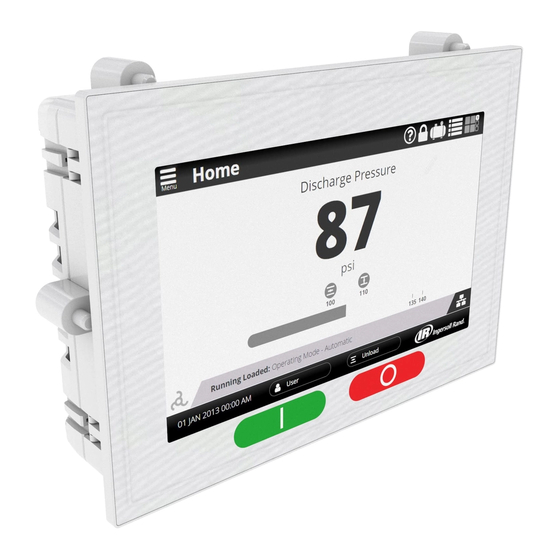
APPROVED 27/Mar/2023 12:32:06 GMT 3.2. Home Screen The Home Screen is the primary screen and typically includes the main information or data needed by the user for safe reliable operation of the compressor. The control system provides three (3) selectable Home Screen styles to choose from, each with the ability to allow some customization. -
Page 20: Schematic And List Screens
APPROVED 27/Mar/2023 12:32:06 GMT Figure 3.2.1 Screen Saver 3.3. Schematic and List Screens In addition to the Tile View, the control system includes a Schematic View and List View, allowing data to be displayed in different perspectives. This concept provides the most comprehensive means of troubleshooting and diagnostics. Although the Schematic View does not have many options or customization, the user is able to select components on the screen, causing the controller to navigate to a schematic view with focus on the component selected. -
Page 21: Figure 3.3-A: Schematic View
APPROVED 27/Mar/2023 12:32:06 GMT Figure 3.3-A: Schematic View Figure 3.3-B: List View P a g e | 21... -
Page 22: Navigation Menu
APPROVED 27/Mar/2023 12:32:06 GMT 3.4. Navigation Menu The main navigation menu provides quick access to all screens in the control system. Access to specific sections or data may not be available depending on user permission at the time. Figure 3.4: Navigation Menu 1. -
Page 23: Logging In
3.5.1 Access Levels Access to operation and configuration of the XS-180 is protected and controlled through three (3) fixed user classes, each with a predefined set of permissions based on the following assumptions: User: The user class is the default and lowest level of access. Intended for personnel who may only need to start and stop the compressor, or review operating parameters, the user has the following limited permissions: ... -
Page 24: Figure 3.5.1: Access Default Passwords
APPROVED 27/Mar/2023 12:32:06 GMT Technician: The technician class is intended primarily for personnel charged with maintaining and troubleshooting individual compressors and air system as a whole. This class, intended for facilities maintenance technicians, distributor technicians and other authorized service providers, inherits all lower level permissions and includes the following additional permissions: ... -
Page 25: Operating The Compressor
APPROVED 27/Mar/2023 12:32:06 GMT 3.6. Operating the Compressor Figure 3.6 Status Bar and Messages To preface this section of Quick Start, there are several steps required to prepare the control system and compressor for service prior to operation. It is recommended that all initial setup, configuration, and commissioning be performed by an authorized service provider. Contact your company representative or closest authorized distributor for more information. -
Page 26: Ready To Start
Starting the Compressor Depending on which options are enabled within the controller, the XS-180 has the ability to receive and process start commands from many sources in addition to the start button located on the UI. This includes a variety of remote and automatic commands, however, regardless of the method used, the controller must be in a "Ready to Start"... -
Page 27: Figure 3.6.2: Start Button
APPROVED 27/Mar/2023 12:32:06 GMT Figure 3.6.2: Start Button P a g e | 27... -
Page 28: Running The Compressor
APPROVED 27/Mar/2023 12:32:06 GMT 3.6.3 Running the Compressor Figure 3.6.3: Running the Compressor After completion of the starting state, the compressor transitions into a running state based on the mode of operation and other options selected during commissioning. Although there are several modes of operation, this Quick Start section will be limited to the Automatic Online /Offline mode. -
Page 29: Stopping The Compressor
APPROVED 27/Mar/2023 12:32:06 GMT 3.6.4 Stopping the Compressor Figure 3.6.4: Stop Button Stopping the compressor can also come from many sources, from manually pressing the stop button to receiving a stop command through a system controller. The way in which the control system processes a stop command may vary depending on the source of it. Although there are multiple sources for this command, this section will focus on manually stopping the compressor by pressing the stop button on the UI. -
Page 30: Active Alarms And Alarm History
APPROVED 27/Mar/2023 12:32:06 GMT Note: pressing the Emergency Stop button is not considered a normal stopping process. It is mechanically hard on components, and is intended for emergency use only. Once the compressor has come to a complete stop, and before it can be returned to service, the user must ensure all operating conditions have returned to normal before resetting the active trip. -
Page 31: Figure 3.7-A: Active Alarms
APPROVED 27/Mar/2023 12:32:06 GMT Figure 3.7-A: Active Alarms The Active Alarm screen lists all warning and trip events not reset. Using the arrows on the right side of the screen, the user can navigate through the list, highlighting each event. With an event highlighted, the user can select the “Info” button to view machine condition data recorded at the time of the event. -
Page 32: Figure 3.7-B: Alarm Info
APPROVED 27/Mar/2023 12:32:06 GMT Figure 3.7-B: Alarm Info Figure 3.7-C: Contact Info P a g e | 32... -
Page 33: Figure 3.7-D: Alarm History
APPROVED 27/Mar/2023 12:32:06 GMT Figure 3.7-D: Alarm History As discussed previously, once an active alarm has been reset, it is moved to and listed within the Alarm History screen. Listed events are arranged in descending order, starting on top with the most recently recorded event. Machine condition captured at the time of the event will persist for the last 50 events, and can be identified when selected by the inclusion of an “... -
Page 34: Settings And Configuration
APPROVED 27/Mar/2023 12:32:06 GMT 4. Settings and Configuration The control system installed on the compressor is pre-configured at the factory for testing purposes, however configuration and setting adjustments are required once installed at site and ready for commissioning. This section provides an overview of the various setting and configuration screens incorporated into the control system. -
Page 35: Initial Setup Settings
APPROVED 27/Mar/2023 12:32:06 GMT 4.1. Initial Setup Settings The Initial Setup category focuses on those screens and fields most likely to be edited only once during commissioning. There are many settings required during commissioning, most of which must be performed by an authorized service provider with technician or higher access permission. The following table includes initial setup settings available for the maintenance and lower permission. -
Page 36: Date & Time
APPROVED 27/Mar/2023 12:32:06 GMT 4.1.2 Date & Time Name: Date & Time | Location: Settings>Configuration>Date & Time Available Fields: Setting Name Description User Rights Maintenance Rights Month Calendar month Calendar day Year Calendar year Hour Hour (24 hour format) Minute Minute Second Second... -
Page 37: Security
APPROVED 27/Mar/2023 12:32:06 GMT 4.1.3 Security Name: Security Location: Settings>Configuration>Security Available Fields: Setting Name Description User Rights Maintenance Rights Change Password Change the password for the logged in user only. (no other administrative rights) Legend: H = Hidden, R = Read Only, RW = Read Write Notes: Maintenance user only has the rights to change their password. -
Page 38: Communication
APPROVED 27/Mar/2023 12:32:06 GMT 4.1.4 Communication The Communication configuration settings screens include all communication protocols available to the maintenance and user class. In an effort to ensure reliable connectivity, it is highly recommended to limit access to, and adjustment of, these settings to trained and authorized personnel only. -
Page 39: Serial Communication
APPROVED 27/Mar/2023 12:32:06 GMT 4.1.4.2. Serial Communication Name: Serial Tab Location: Settings>Configuration>Communication Available Fields: Setting Name Description User Rights Maintenance Rights Mode Selection of available modes for a specific port, including named sequencer and typical Modbus serial modes Baud Rate Select available baud rate for the connection (applies to Modbus selections only) Node ID Select a unique node ID for each device on the serial bus... -
Page 40: Control And Option Settings
APPROVED 27/Mar/2023 12:32:06 GMT 4.2. Control and Option Settings The Control and Option Settings category includes a wide range of setting screens and fields focused on the day to day operation of the compressor. Most screens and fields in this category are available to the maintenance class with “Read Only” visibility for the user class. -
Page 41: Option Settings
APPROVED 27/Mar/2023 12:32:06 GMT Figure 4.2.1: Control Settings 4.2.2. Option Settings Name: Options Location: Settings>Options Available Fields: Setting Name Description User Rights Maintenance Rights Auto Restart Time Amount of time the compressor must run in an unloaded state before stopping in auto restart mode Auto Restart Delay Time Delay time before compressor can restart when commanded to in auto restart mode... -
Page 42: Calibration Settings
APPROVED 27/Mar/2023 12:32:06 GMT Enable Inlet Position Test Enable/disable feature that tests the inlet position Hot Discharge Enable/disable feature providing accommodations for a compressor without an after cooler Legend: H = Hidden, R = Read Only, RW = Read Write Notes: Depending on application installed, some options may not be available. -
Page 43: Programmable I/O Settings
APPROVED 27/Mar/2023 12:32:06 GMT Figure 4.2.3: Calibration Settings 4.2.4. Programmable I/O Settings Name: Programmable IO Location: Settings>Programmable IO Available Fields: Setting Name Description User Rights Maintenance Rights Digital inputs Configure available digital inputs: Remote Load Enable, Remote Load, Remote Start, Remote Stop, Phase Monitor Trip, Auxiliary 1 and 2 Digital outputs Configure available digital outputs for warning and trip indication... -
Page 44: Timer Control (Scheduled Start/Stop & Press Band P2)
APPROVED 27/Mar/2023 12:32:06 GMT Figure 4.2.4: Programmable IO 4.2.5. Timer Control (Scheduled Start/Stop & Press Band p2) Name: Timer Control Location: Settings>Timer Control Available Fields: Setting Name Description User Rights Maintenance Rights Date and Time Link to the date and time described in a previous section. This link is a short-cut Timer Start/Stop Configuration Navigate to Timer Start/Stop screen Button... -
Page 45: Figure 4.2.5-A: Timer Control
APPROVED 27/Mar/2023 12:32:06 GMT Channel Settings Description User Rights Maintenance Rights Start Hour Select and enter the hour to start the compressor (24hr clock, 0-23hr) Start Minutes Select and enter the minutes to start the compressor (0-59min) Stop Hour Select and enter the hour to stop the compressor (24hr clock, 0-24hr) Stop Minute Select and enter the minutes to stop the compressor (0-59min) Day of the Week... -
Page 46: Figure 4.2.5-B: Configuration
APPROVED 27/Mar/2023 12:32:06 GMT Figure 4.2.5-B: Configuration Figure 4.2.5-C: Channel Settings P a g e | 46... -
Page 47: Figure 4.2.5-D: Schedule Overview
APPROVED 27/Mar/2023 12:32:06 GMT Figure 4.2.5-D: Schedule Overview P a g e | 47... -
Page 48: Viewing Data
APPROVED 27/Mar/2023 12:32:06 GMT 5. Viewing Data Operating the compressor can seem overwhelming or too complicated due to the many features, settings, and options that can be incorporated into it. Proper organization and presentation of data reduces the complexity associated with operating the compressor, and makes navigating the controller more intuitive. -
Page 49: Trends Screen Editing
APPROVED 27/Mar/2023 12:32:06 GMT Figure 5.1-B: Edit Metric Screen 5.2. Trends Screen Editing Name: Trends Location: Trends (Main Menu Item) Available Fields: Main Trend View Setting Description User Rights Maintenance Rights Left Y-Axis Drop Down Drop down box providing access to the available selection of parameters to chart Right Y-Axis Drop Down Drop down box providing access to the available selection of parameters to chart Graph Setup... -
Page 50: Figure 5.2-A: Trend View
APPROVED 27/Mar/2023 12:32:06 GMT Time Span Total chart length (time) for display on screen. Available times: Default is 300 sec (5 min), 1 hr, 3 hrs, 6 hrs, 12 hrs Save and Cancel Save chart or cancel and return to the previous screen Legend: H = Hidden, R = Read Only, RW = Read Write Notes:... -
Page 51: List View Editing
APPROVED 27/Mar/2023 12:32:06 GMT Figure 5.2-B: Graph Setup 5.3. List View Editing Name: List View Edit Location: Home Available Fields: Setting Name Description User Rights Maintenance Rights Edit Custom List Press this button while in Custom List View to navigate to the Customized List editing screen Snapshot Press this button to take and store snapshot of the current list readings... -
Page 52: Service Dashboard
APPROVED 27/Mar/2023 12:32:06 GMT Figure 5.3-A: Custom List View Figure 5.3-B: Edit Custom List 5.4. Service Dashboard In addition to the Home and Trends screens, the Service Dashboard provides users and maintenance personnel information on the remaining life of the various filters and coolant installed on the compressor (consumables). With this information, maintenance can be scheduled in advance, minimizing unexpected downtime and costly repairs. -
Page 53: Figure 5.4-A: Service Dashboard Example
APPROVED 27/Mar/2023 12:32:06 GMT class. Within the dashboard, each consumable item is shown as a horizontal bar graph depicting the life and any associated limits. Additionally, service counters are provided to track the life cycle of components that may have a definitive life span. Limits are applied to these components as well to inform users when components become aged and may begin experiencing failure. -
Page 54: Web Interface
APPROVED 27/Mar/2023 12:32:06 GMT 5.5. Web Interface The Web Interface serves as a portal or remote user interface option for users looking to gain access to the compressor from an office desktop or off-site location. Using the Ethernet connection explained earlier, the web interface relies on those configuration settings for connectivity. -
Page 55: Figure 5.5-B: List View Example
APPROVED 27/Mar/2023 12:32:06 GMT Figure 5.5-B: List View Example P a g e | 55... -
Page 56: Diagnostics
APPROVED 27/Mar/2023 12:32:06 GMT 6. Diagnostics Diagnostics are a critical component of any reliable control system. The control system incorporates several methods of providing diagnostic information, including the local UI, web interface, and those covered by the installed IoT system. This section focuses on the overview of the systems that make up the diagnostic suite. -
Page 57: Figure 6.1-B: Local Diagnostic Screens
APPROVED 27/Mar/2023 12:32:06 GMT Figure 6.1-B: Local Diagnostic Screens Figure 6.1-C: Local Diagnostic Screens P a g e | 57... -
Page 58: Figure 6.1-D: Local Diagnostic Screens
APPROVED 27/Mar/2023 12:32:06 GMT Figure 6.1-D: Local Diagnostic Screens Figure 6.1-E: Local Diagnostic Screens P a g e | 58... -
Page 59: Figure 6.1-F: General Diagnostic Screens
APPROVED 27/Mar/2023 12:32:06 GMT Figure 6.1-F: General Diagnostic Screens Figure 6.1-G: Audit Diagnostic Screens P a g e | 59... -
Page 60: Figure 6.1-H: Communication Diagnostic Screens
APPROVED 27/Mar/2023 12:32:06 GMT Figure 6.1-H: Communication Diagnostic Screens Figure 6.1-I: Remote Commands Diagnostic Screens P a g e | 60... -
Page 61: Integrated System Control
APPROVED 27/Mar/2023 12:32:06 GMT 7. Integrated System Control “Integrated System Control” is incorporated in every controller. It has the ability to connect and integrate multiple compressors as one system, providing shared load, sequencing and capacitance to help ensure consistent air production for processes and production in the plant. The following provides an overview of the integrated system controls currently implemented within each controller. -
Page 62: Setup, Pressure Sensor For Leading Machines
APPROVED 27/Mar/2023 12:32:06 GMT 7.1.2. Setup, Pressure sensor for leading machines For a compressor intended to act as a lead machine, it will be necessary to install and configure the “Sequence System Pressure” sensor. This sensor takes the place of the Remote sensor input. Figure 7.1.2 Settings >... -
Page 63: Setup, Sequencing Configuration
APPROVED 27/Mar/2023 12:32:06 GMT 7.1.3. Setup, Sequencing Configuration Figure 7.1.3: Settings > Sequencing 7.1.3.1. Unit Number The “Unit Number” defines the address on the AirSmart network, which this compressor might be using. Each machine needs a unique address and if more than one machine is assigned the same Unit number, operation of sequence control will not operate as described. However, each node will follow all of its local safety overrides for any type of system control. -
Page 64: Transfer Load Decrement
APPROVED 27/Mar/2023 12:32:06 GMT “Transfer Interval” controls how often the group Lead is transferred to a dormant machine during periods of low demand. This parameter is referenced to the total hours’ value. It is critical for all lead candidates in a network to have the same value if the goal is to balance usage among machines. -
Page 65: Startup
APPROVED 27/Mar/2023 12:32:06 GMT Figure 7.1.4: Settings > Control 7.1.4.1. Startup Upon network startup, the AirSmart lead with the following parameters shall start as the lead unit: The largest capacity unit shall be lead. If the units are of equal capacity, the unit with the lowest value of “Total Hours + hour offset” shall be the lead. ... -
Page 66: Delcos Sequencing
APPROVED 27/Mar/2023 12:32:06 GMT 7.2. Delcos Sequencing Delcos must be set up as either a lead using “client enable”, or the “Unit Number” must be configured with a value between 1 and 12. Note that a compressor controller client is limited to controlling only units 1 to 4, while an external sequencer called “Connect 12” may control up to 12 units. Only one Delcos lead should be configured on a network. -
Page 67: Setup, Pressure Sensor For Lead Machine
APPROVED 27/Mar/2023 12:32:06 GMT 7.2.2. Setup, Pressure sensor for lead machine For a compressor intended to act as a lead machine, it will be necessary to install and configure the sequence system pressure sensor. This sensor takes the place of the remote sensor input. Figure 7.2.2: Settings >... -
Page 68: Operation
APPROVED 27/Mar/2023 12:32:06 GMT Setting Minimum Value Maximum Value Default Value Description Client Enable Designates which machine in the sequenced network is the client. Only a single machine in the network can have client enable turned ‘ON’. Client enable must also set to ‘OFF’... -
Page 69: Diagnostics
APPROVED 27/Mar/2023 12:32:06 GMT Defining a new sequence based on Hours Run (BLS): When the transfer interval has expired, the client defines a new sequence based on the hours run (BLS) of the compressors. The compressor with the least hours run (BLS) is placed first in the sequence, etc. “Sequencing diagnostics”... -
Page 70: Figure 7.2.5-B: Diagnostics > Sequencing
APPROVED 27/Mar/2023 12:32:06 GMT Figure 7.2.5-B: Diagnostics > Sequencing P a g e | 70... -
Page 71: Reference Information
APPROVED 27/Mar/2023 12:32:06 GMT 8. Reference Information This section provides information and details available to support the user. 8.1. Modbus Register Table Modbus Register Data Access Type Notes Major Trip Code 0 ASCII Character Code The most recent Trip code in the Active Alarms page on the controller. - Page 72 APPROVED 27/Mar/2023 12:32:06 GMT Major Warning Code 1 ASCII Character Code Part of second warning code on the active alarms page Minor Warning Code 1 Integer Part of second warning code on the active alarms page Major Warning Code 2 ASCII Character Code Part of third warning code on the active alarms page...
- Page 73 APPROVED 27/Mar/2023 12:32:06 GMT 2073 New Controller time, Day Byte New month, range 1 to 31 2074 New Controller time, Hour Byte New hour, range 0 to 23 2075 New Controller time, Minute Byte New minute, range 0 to 59 2076 New Controller time, Second Byte...
- Page 74 APPROVED 27/Mar/2023 12:32:06 GMT 2203, 2213, 2223, 2233, Scheduled Start/Stop Day 0 Boolean Flag indicating Scheduled Start/Stop channel (1 – 8) 2243, 2253, 2263, 2273 Enabled Day 0 (Monday) is enabled 2204, 2214, 2224, 2234, Scheduled Start/Stop Day 1 Boolean Flag indicating Scheduled Start/Stop channel (1 –...
- Page 75 APPROVED 27/Mar/2023 12:32:06 GMT...
- Page 76 APPROVED 27/Mar/2023 12:32:06 GMT ingersollrandproducts.com © 2022 Ingersoll Rand...
- Page 77 APPROVED 27/Mar/2023 12:32:06 GMT...
Need help?
Do you have a question about the XS-180 and is the answer not in the manual?
Questions and answers