Veeder-Root TLS2 Manual
Site prep manual
Hide thumbs
Also See for TLS2:
- Setup and operation manual (328 pages) ,
- Serial interface manual (165 pages) ,
- Upgrade manual (13 pages)

Related Manuals for Veeder-Root TLS2


Summary of Contents for Veeder-Root TLS2
- Page 1 Manual No: 577013-756 ● Revision: J Veeder-Root TLS2 Console Gilbarco EMC2 Console Site Prep Manual...
- Page 2 Customer Service will work with production facility to have the replacement product shipped as soon as possible. If “lost” equipment is delivered at a later date and is not needed, Veeder-Root will allow a Return to Stock without a restocking fee.
-
Page 3: Table Of Contents
Table of Contents Introduction Contractor Certification Requirements ................1 Related Manuals .......................1 Safety Symbols .........................2 Control Drawing .......................3 National Electrical Code Compliance ................4 Probe-to-Console Wiring ..................4 Power Wiring ......................4 Probe Junction Boxes....................4 Probe Wiring Safety Issues ....................5 Console Installation Selecting a Console Location ...................6 Accessing the Console’s Mounting Holes ..............6 Console Dimensions ......................7 Mounting the Console .......................8... - Page 4 DB-9 Connector Pin-Outs ....................37 Comm Port 2 Pin-Outs ....................37 Figures Figure 1. Control Drawing - Example TLS2/EMC2 System Site Layout ....3 Figure 2. Console Dimensions and Designated Wiring Entry Knockouts ....7 Figure 3. Recommended Mounting of Console - International Installations .....8 Figure 4.
-
Page 5: Contractor Certification Requirements
Setup and Operation manual. Contractor Certification Requirements Veeder-Root requires the following minimum training certifications for contractors who will install and setup the equipment discussed in this manual: Installer (Level 1) Certification: Contractors holding valid Installer Certification are approved to perform wiring and conduit routing;... -
Page 6: Safety Symbols
Introduction Safety Symbols Safety Symbols The following safety symbols are used in this manual to alert you to important safety hazards and precautions. EXPLOSIVE FLAMMABLE Fuels and their vapors are extremely Fuels and their vapors are extremely explosive if ignited. flammable. -
Page 7: Control Drawing
Circuitry within the console barrier forms an intrinsically safe, energy-limited system. This system makes console probes safe for use in a Class I, Group D hazardous locations. Console probe wiring is intrinsically safe only when connected to Veeder-Root/Gilbarco Consoles. Reference Console Form Number 8560 and Probe Form Numbers 8462, 8463, 8468, and 8473. -
Page 8: National Electrical Code Compliance
1000 feet (304 m). Wire runs must be less than 1000 feet to meet intrinsic safety requirements. Splices Veeder-Root recommends that no splices be made in the wire run between a probe junction box and the console. Each splice degrades signal strength and could result in poor system performance. Wire Gauges - Color coded Shielded cable must be used in all installations. -
Page 9: Probe Wiring Safety Issues
If the TLS2/EMC2 System is being retrofitted into a paved site, you run direct burial cable to the probes, and then seal over the cable grooves. Before trenching, you should diagram all conduit runs between the console’s intended location and its deployed probes. -
Page 10: Console Installation
Console Installation Selecting a Console Location WARNING Explosive vapors or flammable liquids could be present near locations where fuels are stored or being dispensed. The console is not explosion proof. An explosion or fire resulting in serious injury or death, property loss and equipment damage could occur if the console is installed in a volatile, combustible or explosive atmosphere (Class I, Division 1 or 2). -
Page 11: Console Dimensions
(51 mm) 0.93'' 0.93'' 1.25'' (24 mm) (24 mm) (32 mm) 0.4'' tls2\dimen.eps (10 mm) 3.75" 1.18'' (95mm) (30 mm) Legend for numbered boxes Console mounting holes - 4 places. 1/2-inch I.P.S. & 0.56 inch (22 and 14 mm) - Power wiring only conduit knockouts (4 places). -
Page 12: Mounting The Console
Mounting the Console Install 1/2-inch I.P.S. (14 mm) metal conduit between the console and the power panel as shown in Figure 3 for international installations or Figure 4 for U.S. installations. consoles\tls2\mnt.eps Legend for numbered boxes 2A neon spur To an external alarm (i.e., forecourt alarm) 1000 mm, maximum Communication cable. -
Page 13: Figure 4. Recommended Mounting Of Console - Alternate Installations
Console Installation Mounting the Console consoles\tls2\mntUS.eps Legend for numbered boxes To an optional overfill alarm Communication cable. A dedicated circuit breaker rated for 15 amperes, 120 Vac or 240 Vac. NOTE, circuit breaker must be marked as the power disconnect for the console. Run three 14 AWG standard color coded wires; live, neutral, and earth, to the console. Run one 12 AWG wire, color coded green, from the earth bus bar at the distribution panel direct to the console location. -
Page 14: Wiring The Console
Console Installation Wiring the Console Wiring the Console WARNING The console contains voltages which can be lethal. It is connected to devices that must be intrinsically safe. Connecting power wires to a live circuit can cause electrical shock that may result in serious injury or death. -
Page 15: Figure 5. Wiring Ac Power To The Console
C24/C27 or the metal bands on chokes L2/L4. consoles/tls2/pcon.eps Legend for numbered boxes Attach neutral wire (N) to top terminal (J5). Attach hot wire (L) to bottom terminal (J5). Attach chassis ground wire to ground lug. -
Page 16: Cpu Board Component Locations
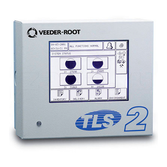
Figure 6 shows important component locations on the CPU board. 2 3 4 OPEN LED2 CONTRAST PGM1 consoles/tls2/display.eps 11 12 Legend for numbered boxes Console features ibutton (under display) Door (reference) Liquid crystal touch screen display Filtered probe data indicator... -
Page 17: Determining Mag Probe Length
2. Measure the distance from the bottom of the probe riser pipe to the top of the probe riser pipe (B). 3. Subtract (B) from (A) to determine the correct tank diameter (C). Round tank diameter (C) up to next highest inch and order this length probe. consoles/tls2/figure6.eps Legend for numbered boxes Tank 24”... -
Page 18: Special Mag Probe Installation Kits
3/8” Adaptor nut 329972-002 3/8” Straight liquidtite connectors and related parts 576008-295 Cord Grip Group 331028-001 tls2/astkit.eps Legend for numbered boxes Cord grip Flexible conduit 5 ft (1.5 m) Liquidtight connector assembly (at riser cap) Liquidtight connector assembly (at J-box) -
Page 19: Riser Cap Kit For Mag Probe Installations
Part Number Plastic Riser Cap 331106-001 Gasket 331140-001 Bushing - Cord Grip 330787-001 Nut - Cord Grip 330594-001 tls2\risercap.eps Legend for numbered boxes Cord grip nut Cord grip bushing Riser cap and gasket Figure 9. Cap and Cord Grip Kit... -
Page 20: Metal Cap And Ring Kit
Special Mag Probe Installation Kits Riser Cap Kit for Mag Probe Installations METAL CAP AND RING KIT This riser cap kit contains a metal ring which screws onto the 4-inch NPT riser and a quick-release metal cap which clamps onto the ring (Table 3). The cap comes drilled and tapped with a cord grip (Figure 10). Table 3. -
Page 21: Modifying An Existing Metal Cap
Special Mag Probe Installation Kits Riser Cap Kit for Mag Probe Installations MODIFYING AN EXISTING METAL CAP In order to ensure that the riser cap seals properly to the probe cable and riser, we recommend that you purchase one of the kits available for this purpose. Riser Caps from other manufacturers may require modification. If you use your own metal riser cap, you must drill and tap it for a cord grip fitting (V-R P/N 331028-001) as follows: 1. -
Page 22: Mag Probe Assembly
Mag Probe Assembly The following assembly instructions are for Global Mag Plus and Mag Plus probes. For other probe types follow assembly instructions included with probe. Attaching Probe Canister Spacer Rings Open the probe shipping carton so that you have access to the probe. Also open the installation kit. For 3- and 4-inch risers After adjusting the spacers for a 3- or 4-inch riser, install the two spacer rings as shown in Figure 12. -
Page 23: Figure 12. Installing Probe Canister Spacer Rings For 3- & 4-Inch Risers
Mag Probe Assembly Attaching Cable Connector to Probe Canister tls2/figure12.eps Legend for numbered boxes After setting arms (see insert) install top spacer ring. Orient locking tabs as shown, and then slide ring over top of canister until tabs snap into groove in canister. -
Page 24: Figure 13. Installing Insulating Sleeves For 2-Inch Risers
Mag Probe Assembly Attaching Cable Connector to Probe Canister probes\sleeveinst2.eps Legend for numbered boxes Canister connector up Sleeve tabs up (snap into canister groove) Canister insulator sleeves (2). Probe shaft Sleeve tabs down (snap into canister groove) Probe canister Figure 13. Installing Insulating Sleeves for 2-inch Risers... -
Page 25: Figure 14. Probe Float/Boot Installation
Mag Probe Assembly Attaching Cable Connector to Probe Canister tls2/figure13.eps Legend for numbered boxes Bottom of probe shaft 4-Inch Float set Product float - slide on probe shaft first Optional Water float OR (6) Water/Density float - slide on probe shaft second. -
Page 26: Mag Probe Installation
At sites that require installation of a riser adaptor (Phil-Tite M/F 4X4 or equivalent) at the top of the riser, do so following the manufacturer’s instructions. Next screw the adapter ring from the Veeder-Root kit (P/N 312020- 952) onto the riser adaptor by hand until the gasket contacts the sealing surface. Then use a torque wrench attached to an appropriate strap wrench (K-D Specialty tools nylon strap oil filter wrench, or equivalent) and tighten the ring to 35 - 45 ft-lbs. -
Page 27: Figure 15. Probe Installation Example - Underground Storage Tank
Mag Probe Installation UST/AST Tank - Dedicated Riser Adaptor Nut on one end and the J-box on the other. Tighten the fittings until snug. Splice and seal the wires in the J-box (see Probe Field Wiring on page 28). probes\pinst.eps Legend for numbered boxes Riser cap and cord grip 14-inch diameter or larger manhole... -
Page 28: Figure 16. U.s. Probe Installation Example - Above Ground Storage Tank
Mag Probe Installation UST/AST Tank - Dedicated Riser probes\apins.eps Legend for numbered boxes Riser cap and cord grip Use bushing and body of grip fitting supplied with probe and adaptor nut supplied with AST kit (V-R P/N 312020-984 Liquidtight fittings from AST kit Flexible metal conduit supplied with AST kit Weatherproof junction box with 1/2”... -
Page 29: Probe Conduit Installation
Mag Probe Installation Probe Conduit Installation probes\riserdapttls2.eps Legend for numbered boxes Metal cap from kit Adaptor ring from kit Riser adaptor (Phil-Tite M/F4X4, or equivalent) Tank Figure 17. Installing the Riser Adaptor Probe Conduit Installation WARNING Probes operate in areas where flammable liquids and explosive vapors may be present. -
Page 30: Rigid Conduit
Also, if the intrinsically safe wires enter the building in a wiring trough, only intrinsically safe wires (from TLS2 probes) can be in the trough. Keep all low power (intrinsically safe) wiring physically isolated from high power wires in all wiring troughs per the NEC. -
Page 31: Direct Burial
Prior to installing direct burial cable with epoxy splices, consult with the local authority having jurisdiction. Use of direct burial cable is only allowed in locations where local codes permit the use of buried cable. If you decide to use the direct burial method, you should order the Veeder-Root Direct Burial Cable Preparation Kit, P/N 848100-500. -
Page 32: Probe Field Wiring
Mag Probe Installation Probe Field Wiring Probe Field Wiring Figure 20 diagrams a typical probe field wiring connection in the junction box. consoles/tls2/pw.eps Legend for numbered boxes To console Seal off Do not ground drain wire in junction box Black wire (-) from probe... -
Page 33: Direct Burial Cable
Contains: epoxy resin and Cycloaliphatic epoxycarboxylate. Precautions: Wear suitable protective clothing, gloves, eye, and face protection. Use only in well ventilated areas. Wash thoroughly before eating, drinking, or smoking. consoles/tls2/epxy.eps Legend for numbered boxes NOTE: When temperature is below 50°F (10°C), keep resin in a warm place prior to mixing (e.g., in an inside pocket next to body).Remove guard bag, using caution not to damage inner bag. -
Page 34: Connecting Probes To The Console
Mag Probe Installation Connecting Probes to the Console Connecting Probes to the Console WARNING The equipment is used in location where lethal voltages and explosive vapors or flammable fuels may be present. Care must be taken when installing, servicing or replacing parts in the system or serious injury or death from explosion, fire or shock may occur. -
Page 35: Figure 22. Connecting Probe Wiring To Console
PROBE 1 AVERTISSEMENT LA SUBSTITUTION DE COMPOSANTS PEUT COMPROMETTRE LA SECURITE INTRINSEQUE. consoles/tls2/pbwr.eps Legend for numbered boxes Circuit Directory label Black wire from probe 1 connects to (-) terminal White wire from probe 1 connects to (+) terminal Attach probe 1 cable shield and /or drain wire to ground lug Intrinsically safe wiring cover (shown swung open to left) Figure 22. -
Page 36: Overfill Alarm Relay
C24/C27 or the metal bands on chokes L2/L4. consoles/tls2/rcon.eps Legend for numbered boxes Connect one wire from relay to top terminal of J6 (no polarity) Connect second wire from relay to lower terminal of J6 (no polarity) -
Page 37: Applying Power To System
Pins (jumper on pins 2&3) (jumper on pins 1&2) consoles/tls2/ram.eps Figure 24. RAM Clear Jumper Positions 2. Move the jumper down to the RAM Clear position (pins 1&2). Turn the power to the console ‘On’ and wait until the console completely boots up. -
Page 38: Warm Boot
Applying Power to System Warm Boot NO TANKS CONFIGURED Figure 25. Cold boot ‘No Tanks Configured’ message Warm Boot After the system has been setup, and power to the console is switched ‘Off’ and ‘On’ , the software will run a self- diagnostic warm boot program and display the test results: Test Passed Message Test Failed Message... -
Page 39: Communications
TO A DEVICE LESS THAN 50 FEET (15 METRES) FROM THE CONSOLE Veeder-Root recommends that you use a null-modem cable no longer than 50 feet for direct connections between the console and a remote device. Cable runs longer than 50 feet can result in data errors, component damage, or both. -
Page 40: Figure 26. Example Of Console Connected To A Remote Device Via Mde800A Short-Haul Modems
Communications Surge Protection for Communication Devices 12 11 10 9 19 18 17 16 consoles\tls2\shm.eps Legend for numbered boxes DB9 connector or (2) DB25 connector - depends on availability Personal Computer Twisted pair 24 or 26 AWG (0.2 mm ) cable... -
Page 41: Db-9 Connector Pin-Outs
Pin layout to connect the console’s Serial Interface DB-9 connector to a 25-pin computer terminal connector are shown in Table 1 below. These connections are standard for “AT” style modem cables. Table 4. TLS2/EMC2 DB-9 Pin-Outs Console (DB-9) Computer (DB-25) - Page 42 For technical support, sales or other assistance, please visit: www.veeder.com...
Need help?
Do you have a question about the TLS2 and is the answer not in the manual?
Questions and answers