Table of Contents
Advertisement
Quick Links
LUXOMAT
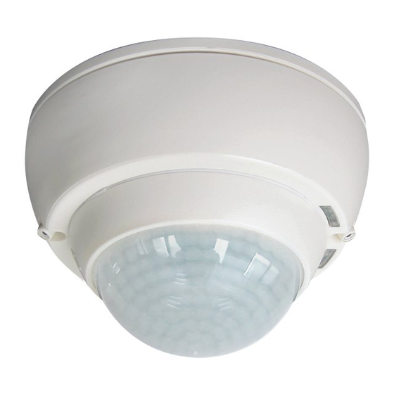
Installation and operating instructions for B.E.G.occupancy detector PD4-M-TRIO-2DALI/DSI-1C
1. Product information
•
For operation of up to 50 electronic ballasts, divided into
two separate groups (25 per channel), via broadcast
command
•
Suitable for dimmable digital electronic ballasts and
control modules
•
One additional switching channel (NO potential-free, dry)
for blackboard illumination or controlling HVAC (heating,
ventilation, air conditioning) devices
•
DALI/DSI interface
•
Constant light control (channel 1, channel 2)
•
Manually switching / dimming the individual channels by
means of separate pushbuttons
•
Fully or semi-automatic mode
•
Set value brightness, follow-up time – LIGHT/HVAC and
orientation light adjustable
•
Light measurement with two separate light sensors for wall
and window side
•
Sensor and power supply in one housing
•
Infrared remote control
2. Operation
The presence detector controls the light automatically depending
on movement and ambient brightness.
The two integrated light sensors constantly measure the ambient
light at the wall and window side and compare the measured
values with the brightness level set in the detector. Thereafter,
the two light bands are regulated individually. If the ambient
light is sufficient, lighting will not be switched on. If the ambient
light level is below the brightness level, a movement activates the
lighting in the room.
If there is enough natural light for 5 min, the detector switches
the lighting off despite of people being present. After elapse of
the follow-up time and no movement detected, the detector also
switches the light off automatically. The third channel is designed
as a relay contact and can selectively be used for blackboard
illumination (ON/OFF) or for controlling devices (HVAC). In this
case, the channel switches the connected load independent of
the brightness.
3. Safety advice
Work on the 230V mains supply may only be carried
!
out by qualified professionals or by instructed persons
under the direction and supervision of qualified skilled
electrical personnel in accordance with electrotechnical
regulations.
Disconnect supply before installing!
!
The device is not suitable for disconnection.
!
After having connected all cables, please mount the
!
cap onto the detector.
4. Mounting
PD4-M-TRIO-2DALI/DSI-1C-SM
open
close
The detector has to be installed on a solid and plane surface. The
lens has to be removed prior to mounting. To do this, twist the lens
anti-clockwise through approximately 5° and lift off. After having
connected up the wires in accordance with regulations, secure the
detector with 2 screws. After installation replace the lens and lock
(turn clockwise).
100 mm
PD4-M-TRIO-2DALI/DSI-1C-FC
A circular opening of diameter 100mm has to
be produced in the ceiling.
After having connected up the cables in
accordance with regulations, insert the
detector into the opening as shown and fix it
into position with the retaining bracket using
screws.
In Master/Slave operation, the master
device has to be mounted at the place
having less ambient light.
PD4-M-TRIO-2DALI/DSI-1C
®
5. Position of potentiometers and DIP switches
3
5 1
A
4
2 6
3
1
DIP
DIP
321
2
3 2
1
B
SM
6
5
DIP 1
Semi-automatic/
4
Fully automatic mode
A
3
DIP 2
Ini OFF/ON
2
Lamps at start-up
1
OFF/ON
DIP 3
RESET
A
Light sensor channel 1 | B
Light sensor channel 2
1
LED red OFF function
2
LED green too bright/too dark CDS 2
3
LED white semi-automatic Channel 1C
4
LED white semi-automatic DA 1/2
5
LED green too bright/too dark CDS 1
6
LED red motion indicator/walking test
6. Self-test cycle / Start-up behaviour
After having first connected the supply, the device enters an initial
60-second self-test cycle. During this time, the device does not
respond to movement and stays on. DIP switch 2 can be used for
turning off the illumination during the self-test cycle.
RESET via DIP switch
During operation, DIP switch 3 has to be put in its OFF position.
Otherwise, the detector re-starts the self-test cycle.
7. Putting into operation / Settings
Potentiometer 3: Follow-up time "light"
The time can be set at between 1 and 60 minutes. The
45
60
time-setting is valid for all three channels.
30
Symbol TEST: Test mode
15
TEST
5
Every movement switches the light ON for a period of
1
2 seconds, afterwards OFF for a period of at least 2
seconds.
Potentiometer 2: Brightness value for constant light
1200
control
600
The set value brightness can be set at between 10
200
and 1200 Lux. Using the potentiometer, the set values
40
brightness can be adjusted as desired.
Symbol
: Night-time operation | Symbol
me/Night-time operation
ON
Potentiometer 1: Orientation light (20% of the nominal
60
45
value)
30
15
Manually switching ON and OFF the orientation light.
5
OFF
"ON" for permanent orientation light.
"OFF" for switching off the orientation light.
DIP1
Fully automatic operation
In this operating mode, the lighting switches automatically on
and off for increased comfort, depending on presence and
brightness.
Semi-automatic operation (all three channels)
In this operating mode, in order to gain increased savings, the
lighting can only be switched on manually by using the pushbut-
ton or the remote control. It can be switched off automatically
or manually.
80 - 90 mm
The semi-automatic mode basically behaves like the fully auto-
matic mode. However, the difference is that switching on always
has to be carried out manually!
8. Wiring diagram – Standard mode with Master-
TRIO-2DALI/DSI-1C occupancy detectors
L
N
3
2
1
T1
FC
S
DA1/2
HVAC/Light
Master
optional
T1&2 = NO button for semi-automatic mode
B
Slave for enlargement of detection area
9. Manual switching and dimming
By means of the push button, the phase can be given to the
desired S terminal (T1 and T2). A short press of the pushbut-
ton switches the light on or off. A long press of the pushbutton
is for dimming. When releasing the pushbutton, the current
dimming value is kept. Another press of the pushbutton reverses
the dimming direction. The light remains on or off as long as
movement is detected, plus the set follow-up time. Afterwards, the
device automatically returns in the selected operating mode (fully
automatic or semi-automatic).
10. Detection area/range
2,50 m
11. Exclude sources of interference
: Dayti-
If the detection zone of the
DSI-1C is too large, or areas are covered that should not
be monitored, use the blinds (included) to reduce or limit
those areas.
12. Technical data PD4-M-TRIO-2DALI/DSI-1C
Sensor and power supply in one housing
Power supply:
Power consumption:
Ambient temperature:
Degree of protection/class:
Recommended
mounting height:
Range of coverage Ø H 2.50 m / T = 18°C:
seated 6.40m / tangential 24m / radial 8m
Detection area:
Dimensions H x Ø [mm]:
Visible portion when built
into ceiling H x Ø [mm]:
Light values - Potentiometer: 10 – 2000 Lux
L
N
E1 DALI
DA
DA
L
N
E2 DALI
DA
T2
DA
HVAC/Light
S
N
L
+
-
+
NO NO
R
R
DA1
DA2
HVAC/Light
Slave
1
Walking across
2
Walking towards
Seated
LUXOMAT
®
PD4-M-TRIO-2DALI/
110-240 VAC, 50/60 Hz
approx. 1W
-25°C – +50°C
IP20 / II
2 – 3m
circular 360°
SM
FC
124 x 85 97 x 103
37 x 117mm
GB
N
L
Advertisement
Table of Contents

Subscribe to Our Youtube Channel
Related Manuals for B.E.G. LUXOMAT PD4-M-TRIO-2DALI DSI-1C


Summary of Contents for B.E.G. LUXOMAT PD4-M-TRIO-2DALI DSI-1C
- Page 1 LUXOMAT PD4-M-TRIO-2DALI/DSI-1C ® Installation and operating instructions for B.E.G.occupancy detector PD4-M-TRIO-2DALI/DSI-1C 1. Product information 5. Position of potentiometers and DIP switches 8. Wiring diagram – Standard mode with Master- TRIO-2DALI/DSI-1C occupancy detectors • For operation of up to 50 electronic ballasts, divided into...
- Page 2 DALI/DSI: DA 1 and DA2 for light control 15. Putting into operation of the remote control The semi-automatic mode basically behaves like the fully auto- depending on brightness matic mode. The only difference is that the switching on has to IR-PD-DALI-1C (optional) (broadcast per channel) be done by hand, always!
Need help?
Do you have a question about the LUXOMAT PD4-M-TRIO-2DALI DSI-1C and is the answer not in the manual?
Questions and answers