Advertisement
Quick Links
LUXOMAT
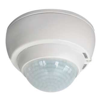
Installation and Operating Instruction for B.E.G. - Occupancy detector PD4-M-TRIO-C-3P-SM
1. Product information
1-channel occupancy detector with two simultaneously-
„
working relay outputs which enable division across different
phases.
„ The switching channel with the two relay outputs closes if
the detector power supply fails, so that the lighting remains
on as long as both phases of the lights are supplied with
power.
„ Especially for corridors
„ Master version
„ Extension of the detection area by slave devices is possible
„ Manual switching via push-button possible
„ Other functions adjustable by remote control (optional)
2. Functionality
The PD4-M-TRIO-C-3P can be connected to three different
electric circuits (phases). The first electric circuit supplies the
operating voltage, the other two electric circuits can be switched.
A lighting system can therefore be split into two galvanically
separated groups.
For increased operational safety the PD4-M-TRIO-C-3P switches
when the operating voltage fails.
The integrated light sensor constantly measures the ambient
light and compares it with the switch-lon threshold defined on
the detector. If the ambient light is sufficient, lighting will not be
switched. If the ambient light level is below the switch-on threshold,
a movement activates the lighting in the room
The detector switches the light off despite of an actual presence
of a person, if there is enough natural light for 5 min or if no
movement is detected for one follow-up time.
3. Safety information
Work on the 110-240 V mains supply may only be carried
!
out by qualified professionals or by instructed persons
under the direction and supervision of qualified skilled
electrical personnel in accordance with electrotechnical
regulations.
!
Disconnect supply before installing!
This device is not suitable for disconnection.
!
For all connected loads, proper interference suppression
!
is obligatory (For all connected loads, proper interference
suppression is obligatory).
The total number of switchable loads is limited due to high
!
inrush currents of electronic ballasts and LED drivers. In
case of a large number of connected loads please use an
external contactor.
4. Montage
The corridor window in the lense is the essential feature for
orientation when mounting the detector.
open
close
PD4-M-TRIO-C-3P
®
Before mounting, the lens must be removed. To remove it, the lens
must be turned about 5° anticlockwise and taken out
Use the supplied screws and wall plugs to mount the socket. After
properly connecting the wiring, the detector must be placed on the
socket and screwed in. Then reattach the lens, turning it clockwise,
and fasten with a screw. Once mounted, the detector can be
adjusted by approx. 90° max.
5. Position DIP switches, LEDs and Potentiometer
I II
III
IV
I
red LED
II
green LED
III
white LED
IV
Lightsensor
Potentiometer TIME:
Follow-up time Light
Potentiometer LUX:
switch-on threshold
Determining current brightness
Set TIME potentiometer to TE position. The green LED shows
a steady light when the value set on the lux potentiometer is
above the current measured brightness value.
DIP switch functions
ON
DIP 1 Semi-automatic mode (HA)
Full automatic mode (VA)
LED (function indicators)
DIP 2 LED (function indicators) OFF
ON
DIP 3 Corridor mode (Corr)
Standard mode (NORM)
Corridor operation: if corridor function is active, the light
!
remains switched off for 5s after manual switch-off even if
movement is detected. Automatic mode is then active again.
6. Full / Semi-automatic mode
Full automatic operation
In this operating mode, the lighting switches automatically
on and off for increased comfort, depending on presence and
brightness. The light switches on when there is movement if the
current light value is below the switch-on threshold.
Semi-automatic operation
The semi-automatic mode basically behaves like the full
automatic mode. The only difference is that the switching
on has to be done by hand.
The main light can be switched on again automatically by
movement within 10s after the follow-up time has passed. After
this time has passed, the switch must be pressed again to switch
on the main light.
Semi-automatic mode can be activated via DIP switches or via
the remote control "HA ON/OFF" command. If semi-automatic
90°
mode is activated, this is indicated by the white status LED
7. Self test cycle
The product enters an initial 60-second self-test cycle, when the
supply is first connected. During this time the device does not
respond to movement and stays on.
8. Light measuring
In order to calculate a switch-off threshold, there is a five-minute
light measurement. For this, the light is switched off by the detector
for all channels for 5s and then switched on for 5 min.
Measurement is carried out if:
„ the level goes below the switch-on threshold
for the very first time
„ the switch-on threshold is changed on a
potentiometer
„ a new switch-on threshold is programmed by remote control
(finish setting up with CLOSE button)
The measurement is not done during the activated test function.
Unlocking the device halts light measurement.
After programming ends, light measurement is restarted.
9. Putting into operation / Settings
Potentiometer TIME - Adjustment follow-up time
TIME
"Light"
2 1
5
30
10
Symbol TE: Test mode, reacts on motion only. Every
15
16
movement switches on the light for a period of 2
seconds, switching it off for a period of 2 seconds
The follow-up time can be set infinitely variably at
between 15 sec. and 16 minutes.
Pulse function
The pulse function can be used to control external
HVAC systems. When movement is detected, a 1s
pulse is sent every 9s.
Potentiometer LUX -
LUX
setting - switch-on threshold
600
1200
200
The switch-on threshold can be set to between
2000
40
approx. 10 and 2000 Lux.
When the detector is set to "Sun", it switches on at every
movement regardless of brightness. (Light analysis disabled)
Factory setting
OFF
If the potentiometers are in "Test" and "Sun" positions,
the factory settings are activated (detector not programmed):
500 Lux and 10 min.
EN
Advertisement

Related Manuals for B.E.G. LUXOMAT PD4-M-TRIO-C-3P


Summary of Contents for B.E.G. LUXOMAT PD4-M-TRIO-C-3P
- Page 1 LUXOMAT PD4-M-TRIO-C-3P ® Installation and Operating Instruction for B.E.G. - Occupancy detector PD4-M-TRIO-C-3P-SM 1. Product information 6. Full / Semi-automatic mode Before mounting, the lens must be removed. To remove it, the lens 1-channel occupancy detector with two simultaneously- must be turned about 5° anticlockwise and taken out Full automatic operation „...
- Page 2 10. Wiring diagram 15. Article / Part nr. / Accessory Standard mode with Master/Slave Part nr. PD4-M-TRIO-C-3P-SM 92747 LUXOMAT® Remote control: IR-PD-1C (incl. wall bracket) 92520 R-PD-1C-E 92077 IR-Adapter for Smartphones 92726 Accessory: Recommended slave: PD4-S-C-SM 92442 Sockel IP54 PD4-TRIO-SM 92836 RC-Arc extinction kit 10880...
- Page 3 18. Putting into operation of the remote control (optional) 20. Explanation of the remote control button functions After activating the function via the “Pulse“ push button, select the desired time within 5s. The DIP switch and potentiometer settings are overriden Pressing a button is confirmed by a short switching of both using the remote control.
Need help?
Do you have a question about the LUXOMAT PD4-M-TRIO-C-3P and is the answer not in the manual?
Questions and answers