Table of Contents
Advertisement
Quick Links
Download this manual
See also:
Instruction Manual
Advertisement
Chapters
Table of Contents
Troubleshooting

Subscribe to Our Youtube Channel
Related Manuals for Sel SEL-421


Summary of Contents for Sel SEL-421
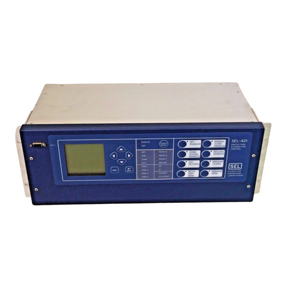
- Page 1 SEL-421 Relay SEL-421-1 Relay Protection Automation Control User’s Guide Schweitzer Engineering Laboratories 2350 NE Hopkins Court Pullman, WA USA 99163-5603 Tel: (509) 332-1890 FAX: (509) 332-7990...
- Page 2 5,367,426; 5,479,315; 5,515,227; 5,652,688; 5,694,281; 5,703,745; 5,731,943; 5,790,418; 5,793,750; 5,883,578; 5,914,663; 6,028,754; 6,084,755; U.S. and Foreign Patent(s) Pending. This product is covered by the standard SEL 10-year warranty. For warranty details, visit www.selinc.com or contact your customer service representative. ã...
-
Page 3: Table Of Contents
Making Simple Settings Changes......................U.4.15 Examining Metering Quantities ........................ U.4.31 Reading Oscillograms, Event Reports, and SER..................U.4.39 Operating the Relay Inputs and Outputs ....................U.4.52 Configuring High-Accuracy Timekeeping ....................U.4.66 Readying the Relay for Field Application....................U.4.72 SEL-421/SEL-421-1 Relay Date Code 20020501... - Page 4 Section 4: Time-Synchronized Measurements Relay Configuration for High-Accuracy Timekeeping ................A.4.2 Fault Analysis ..............................A.4.6 Power Flow Analysis ...........................A.4.7 State Estimation Verification ........................A.4.10 Section 5: Substation Automatic Restoration 230 kV Tapped Transmission Line Application Example ................A.5.2 SEL-421/SEL-421-1 Relay Date Code 20020501...
- Page 5 Table of Contents Section 6: SEL-2030 Applications SEL Communications Processor ......................... A.6.2 SEL-2030 and SEL-421 Relay Architecture ....................A.6.4 SEL-2030 Example ............................. A.6.6 Section 7: Direct Network Communication Direct Network Communication ......................... A.7.2 Serial Networking............................A.7.3 SEL-2701 Ethernet Processor........................A.7.5 Direct Networking Example........................
- Page 6 Serial Communication ..........................R.4.3 Communications Card ..........................R.4.6 Section 5: SEL Communications Protocols Serial Port Hardware Protocol ........................R.5.2 Software Protocol Selections ........................R.5.4 Protocol Active When Setting PROTO := SEL................... R.5.5 Virtual File Interface ..........................R.5.14 SEL M Communications ..................... R.5.18 IRRORED SEL Distributed Port Switch Protocol (LMD) ..................
- Page 7 Table of Contents Appendix C: GOMSFE Tables Introduction ..............................R.C.1 GOMSFE Tables ............................R.C.2 SEL-421 Relay Domains..........................R.C.3 SEL-421 Relay Domain–LN0 ........................R.C.4 SEL-421 Relay Virtual Device Domain ......................R.C.9 Special Translation Rules ..........................R.C.17 Glossary ................................GL.1 Index ................................... IN.1 SEL-421/SEL-421-1 Relay Date Code 20020501...
- Page 8 This page intentionally left blank...
-
Page 9: List Of Tables
Commissioning Testing...................... U.6.3 Table 6.3 Maintenance Testing ......................U.6.3 Table 6.4 UUT Database Entries for SEL-5401 Relay Test System Software—5 A Relay ....U.6.8 Table 6.5 UUT Database Entries for SEL-5401 Relay Test System Software—1 A Relay ....U.6.8 Table 6.6 Phase Instantaneous Overcurrent Pickup ................. - Page 10 Table 1.4 Options for Enabling Pole-Open Logic ................A.1.13 Table 1.5 Setting TULO Unlatch Trip Options ................A.1.14 Table 1.6 SEL-421 Relay Settings....................A.1.16 Table 1.7 System Data—500 kV Parallel Overhead Transmission Lines ........A.1.21 Table 1.8 Secondary Impedances ..................... A.1.21 Table 1.9 LOP Enable Options ......................
-
Page 11: Features........................................................................................................................................................ U
HIS Command........................A.3.32 Table 3.9 SER Commands ....................... A.3.35 Section 4: Time-Synchronized Measurements Table 4.1 SEL-421 Relay Voltage and Current Measurement ............A.4.8 Section 5: Substation Automatic Restoration Table 5.1 Global Settings ........................A.5.6 Table 5.2 Breaker Monitor Settings ....................A.5.6 Table 5.3... - Page 12 Selectable Current Quantities ................... R.1.69 Table 1.51 Selectable Inverse Time-Overcurrent Settings ..............R.1.69 Table 1.52 Selectable Inverse-Time Overcurrent Relay Word Bits............ R.1.70 Table 1.53 SOTF Settings........................R.1.86 Table 1.54 SOTF Relay Word Bits ..................... R.1.86 SEL-421/SEL-421-1 Relay Date Code 20020501...
- Page 13 Auto-Reclose Logic Relay Word Bits ................R.2.31 Table 2.26 Synchronism-Check Relay Word Bits................R.2.45 OGIC ® Section 3: SEL Control Equation Programming Table 3.1 Advanced SEL-421 Relay SEL Control Equation Features........R.3.2 OGIC Table 3.2 SEL-421 Relay SEL Control Equation Programming Summary ........R.3.2 OGIC Table 3.3...
-
Page 14: Index
SEL-421 Relay DNP Object List..................R.6.14 Table 6.10 SEL-421 Relay DNP 3.0 Default Data Map..............R.6.19 Table 6.11 SEL-421 Relay Object 1, 2 Relay Word Bit Mapping ............. R.6.23 Table 6.12 Object 1, 2 Indices 1600—1615 Front-Panel Targets............R.6.26 Table 6.13 Object 30, Index 176 Upper Byte—Event Cause............. - Page 15 List of Tables Table 6.14 Object 30, Index 176 Lower Byte—Fault Type ..............R.6.26 Table 6.15 SEL-421 Relay Object 12 Trip/Close Pair Operation ............R.6.27 Table 6.16 SEL-421 Relay Object 12 Code Selection Operation ............R.6.28 Table 6.17 DNP 3.0 Application Example Data Map .................R.6.29 Table 6.18...
- Page 16 Table 8.91 SER Command ......................... R.8.37 Table 8.92 SER C and SER R Commands ..................R.8.37 Table 8.93 SER CA Commands ......................R.8.37 Table 8.94 SER D Command ......................R.8.38 Table 8.95 SET Command Overview....................R.8.39 SEL-421/SEL-421-1 Relay Date Code 20020501...
- Page 17 Table 9.4 Station DC1 Monitor (and Station DC2 Monitor)...............R.9.4 Table 9.5 Control Inputs (Global) .......................R.9.4 Table 9.6 Main Board Control Inputs ....................R.9.4 Table 9.7 Interface Board #1 Control Inputs..................R.9.5 Table 9.8 Interface Board #2 Control Inputs..................R.9.5 SEL-421/SEL-421-1 Relay Date Code 20020501...
- Page 18 Table 9.61 Breaker 2 Synchronism Check ..................R.9.25 Table 9.62 Recloser and Manual Closing ..................R.9.25 Table 9.63 Single-Pole Reclose Settings .................... R.9.26 Table 9.64 Three-Pole Reclose Settings ..................... R.9.26 Table 9.65 Voltage Elements ......................R.9.27 SEL-421/SEL-421-1 Relay Date Code 20020501...
- Page 19 Table 9.85 Port Settings Categories ....................R.9.38 Table 9.86 Protocol Selection ......................R.9.38 Table 9.87 Communications Settings....................R.9.38 Table 9.88 SEL Protocol Settings .......................R.9.38 Table 9.89 Synchronized Phasor Measurement Settings ..............R.9.39 Table 9.90 DNP 3.0 Protocol Settings ....................R.9.39 Table 9.91 Protocol Settings ..................R.9.40 IRRORED Table 9.92...
- Page 20 GCTL Model (GCTL)—LN0 Domain ................R.C.5 Table C.6 Globe Model (GLOBE)—LN0 Domain ................R.C.5 Table C.7 Models in Virtual Device Domain for SEL-421 Relays............ R.C.9 Table C.8 Device ID Model (DI)—SEL-421 Relay Domain............. R.C.9 Table C.9 Fault Identification Model (FAULT1—FAULT20)—SEL-421 Relay Domain ....R.C.10 Table C.10...
- Page 21 Major Component Locations on the SEL-421 Relay Main Board........U.2.18 Figure 2.14 J18 Header—Password and Breaker Jumpers..............U.2.19 Figure 2.15 Major Component Locations on the SEL-421 Relay INT1 I/O Board......U.2.22 Figure 2.16 Major Component Locations on the SEL-421 Relay INT5 I/O Board......U.2.23 Figure 2.17 Major Component Locations on the SEL-421 Relay INT6 I/O Board.
-
Page 22: Connection................................................................................................................................................. U
Software..........U.4.26 ERATOR Figure 4.17 Software Global Settings Window........... U.4.26 ERATOR Figure 4.18 Uploading Global Settings to the SEL-421 Relay............U.4.27 Figure 4.19 DATE and TIME Settings: Front-Panel LCD..............U.4.28 Figure 4.20 SETTINGS Menus......................U.4.30 Figure 4.21 Setting ESS: Terminal.......................U.4.31 Figure 4.22... - Page 23 Figure 4.59 Setting 52AA1 in the Software............... U.4.64 ERATOR Figure 4.60 Uploading Global and Breaker Monitor Settings to the SEL-421 Relay......U.4.65 Figure 4.61 TIME BNC Jacks......................U.4.67 Figure 4.62 Confirming the High-Accuracy Timekeeping Enable Settings........U.4.68 Figure 4.63...
- Page 24 Software....... U.6.21 ERATOR Figure 6.14 Setting SER Points and Aliases: Software..........U.6.22 ERATOR Figure 6.15 Uploading Group 1 and Report Settings to SEL-421 Relay..........U.6.22 Figure 6.16 HMI Tree View: Software............... U.6.23 ERATOR Figure 6.17 SER Report: HMI..................
- Page 25 SEL-421 Relay Intelligent Circuit Breaker Monitor............A.2.2 Figure 2.2 Circuit Breaker Maintenance Curve (Manufacturer’s Data)..........A.2.5 Figure 2.3 Circuit Breaker Contact Wear Curve With SEL-421 Relay Settings......... A.2.5 Figure 2.4 Trip Bus Sensing With Relay Input IN106................ A.2.8 SEL-421/SEL-421-1 Relay...
- Page 26 Figure 4.4 Selecting Trip Logic and ER Trigger Settings in the Software....A.4.4 ERATOR Figure 4.5 Uploading Group Settings to the SEL-421 Relay............... A.4.5 Figure 4.6 230 kV Transmission Line System..................A.4.6 Figure 4.7 500 kV Three Bus Power System..................A.4.7 Figure 4.8...
- Page 27 Figure 6.2 Multitiered SEL-2030 Architecture................... A.6.3 Figure 6.3 Enhancing Multidrop Networks With the SEL-2030............A.6.5 Figure 6.4 Example SEL-421 Relay and SEL-2030 Configuration............ A.6.6 Section 7: Direct Network Communication Figure 7.1 DNP Multidrop Network Topology..................A.7.3 Figure 7.2 DNP Star Network Topology.
- Page 28 Two Circuit Breakers Three-Pole Cycle State (79CY3)........... R.2.38 Figure 2.17 Partial Breaker-and-a-Half or Partial Ring-Bus Breaker Arrangement......R.2.41 Figure 2.18 Voltage Angle Difference in a Paralleled System............. R.2.42 Figure 2.19 Synchronism-Check Voltages for Two Circuit Breakers..........R.2.43 Figure 2.20 Synchronism-Check Settings.................... R.2.44 SEL-421/SEL-421-1 Relay Date Code 20020501...
- Page 29 List of Figures xxxi Figure 2.21 Synchronism-Check Relay Word Bits................R.2.44 Figure 2.22 Synchronism-Check Voltage Connections to SEL-421 Relay..........R.2.46 Figure 2.23 Synchronism-Check Voltage Reference................R.2.47 Figure 2.24 Normalized Synchronism-Check Voltage Sources VS1 and VS2........R.2.48 Figure 2.25 Healthy Voltage Window and Indication................R.2.49 Figure 2.26...
- Page 30 This page intentionally left blank...
-
Page 31: List Of Equations
Equation 1.11 ............................A.1.29 Equation 1.12 ............................A.1.29 Equation 1.13 ............................A.1.30 Equation 1.14 ............................A.1.30 Equation 1.15 ............................A.1.30 Equation 1.16 ............................A.1.32 Equation 1.17 ............................A.1.33 Equation 1.18 ............................A.1.35 Equation 1.19 ............................A.1.54 SEL-421/SEL-421-1 Relay Date Code 20020501... - Page 32 Equation 1.69 ............................A.1.120 Equation 1.70 ............................A.1.121 Equation 1.71 ............................A.1.121 Equation 1.72 ............................A.1.122 Equation 1.73 ............................A.1.122 Equation 1.74 ............................A.1.123 Equation 1.75 ............................A.1.124 Equation 1.76 ............................A.1.124 Equation 1.77 ............................A.1.124 SEL-421/SEL-421-1 Relay Date Code 20020501...
- Page 33 Equation 3.4 ............................A.3.19 Equation 3.5 ............................A.3.19 Section 4: Time-Synchronized Measurements Equation 4.1 ............................. A.4.8 Section 5: Substation Automatic Restoration Section 6: SEL-2030 Applications Section 7: Direct Network Communication Reference Manual Section 1: Protection Functions Equation 1.1 ............................R.1.30 Equation 1.2 ............................R.1.30 Equation 1.3 ............................R.1.30...
- Page 34 ............................R.2.55 OGIC ® Section 3: SEL Control Equation Programming Section 4: Communications Interfaces Section 5: SEL Communications Protocols Section 6: DNP 3.0 Communications Section 7: UCA2 Communications Section 8: ASCII Command Reference Section 9: Settings Appendix A: Relay Word Bits...
-
Page 35: List Of Examples
Inactivity Time Settings ....................A.2.16 Example 2.10 Motor Running Time Settings ..................A.2.17 Section 3: Analyzing Data Example 3.1 Triggering Event Report/Data Capture Using the ER SEL Control Equation ... A.3.4 OGIC Example 3.2 Including PUL Command Triggering in the ER SEL Control Equation.... - Page 36 OGIC Example 3.24 Converting SEL-311 Series Relay SEL Control Equation Timers ......R.3.37 OGIC Example 3.25 Converting SEL-311 Series Relay Latch Bits ..............R.3.37 Section 4: Communications Interfaces Section 5: SEL Communications Protocols Section 6: DNP 3.0 Communications Section 7: UCA2 Communications...
-
Page 37: Manual Change Information
Initial Release with Synchrophasor Measurement capability to SEL-421. Added VAZ, VBZ, VCZ settings options to SYNCP. Added VAY, VBY, VCY settings options to SYNCS1, SYNCS2 and ASYNCS2. Added ACOS, ASIN, CEIL, FLOOR and LOG math functions to SEL control equations. OGIC... - Page 38 Added Notes to flag the differences in the SEL-421-1 Relay. Reference Manual Appendix A: Relay Word Bits Added Notes to flag the differences in the SEL-421-1 Relay. Index Added index entries for configurable front-panel labels, SEL-421-1 Relay, and series-compensated line. 20010703 Initial Release. SEL-421/SEL-421-1 Relay...
-
Page 39: Preface
Preface This manual provides information and instructions for installing and operating the SEL-421 Relay. The three volumes that comprise this manual are for use by power engineers and others experienced in protective relaying applications. Included are detailed technical descriptions of the relay and application examples. -
Page 40: User's Guide
Index. Also included is a Glossary that lists and defines technical terms used throughout the manual. The SEL-421 Relay Manual is a comprehensive work covering all aspects of relay application and use. Read the sections that pertain to your application to gain valuable information about using the SEL-421 Relay. - Page 41 Section 2: Auto-Reclose and Synchronism Check. the SEL-421 Relay two-circuit breaker multi-shot recloser; describes how to set the SEL-421 Relay for single-pole reclosing, three-pole reclosing, or both; shows selection of the lead and follow circuit breakers; explains how to set and apply synchronism-check elements for automatic and manual closing.
- Page 42 The three volumes of the SEL-421 Relay Manual are represented by the first letter in the page number character string: U is for User’s Guide, A is for Applications Handbook, and R is for the Reference Manual.
- Page 43 To benefit fully from reading this manual, take a moment to familiarize yourself with these conventions. The SEL-421 Relay Manual shows certain information with specific font and Typographic formatting attributes. The following table lists the typographic conventions Conventions used in this documentation.
- Page 44 If your facility is not equipped to work with these components, contact SEL about returning this device and related SEL equipment for service. A CAUTION statement alerts you about unsafe practices that CAUTION: ➤ Equipment damage can result from connecting ac circuits to can possibly cause property damage.
- Page 45 Preface xlvii 11 WARNING Margin notes serve two purposes in the SEL-421 Relay Manual. Notes present Notes valuable or important points about relay features or functions. Use these notes as tips to easier and more efficient operation of the relay. Also in this manual, Notes specify differences between the SEL-421 Relay and the SEL-421-1 Relay models when these differences affect relay functions or operations.
- Page 46 Input S asserts output Q until input R asserts. SET RESET FLIP FLOP Output Q deasserts or resets when R asserts. FALLING EDGE B asserts at the falling edge of input A. Logic Diagram Symbols. SEL-421/SEL-421-1 Relay Date Code 20020501...
-
Page 47: Section 1: Introduction And Specifications
SEL control equation programming into 10 blocks OGIC of 100 program lines each. The SEL-421-1 Relay has the same protection programming capability but has only 1 block of 100 lines of automation programming capability. Both the SEL-421 Relay and the SEL-421-1 Relay provide extensive communications interfaces from standard SEL ASCII and enhanced ITS ™... -
Page 48: Features
U.1.2 Introduction and Specifications Features Features The SEL-421 Relay contains many protection, automation, and control features. Figure 1.1 presents a simplified functional overview of the relay. SEL-421 Relay • Password Separation of Protection and Automation • Expanded SEL ® Control... - Page 49 OGIC includes math and comparison functions. Use counters and multifunction timers for greater application flexibility. Perform advanced PLC functions within the relay. The SEL-421 Relay has separate protection and automation SEL control equation OGIC programming areas. These programming areas provide you with ample protection programming capability and 10 blocks of 100-line automation programming capability (1000 lines).
- Page 50 (LANs) and company wide-area-networks (WANs). Employ UCA and FTP protocols for system data acquisition and control. The SEL-421 Relay divides control and settings into Increased Security. seven relay access levels; the relay has separate breaker, protection, automation, and output access levels, among others.
-
Page 51: Models And Options
Introduction and Specifications U.1.5 Models and Options Models and Options The SEL-421 Relay and the SEL-421-1 Relay have many common features. Consider the following options when ordering and configuring these relays. ➤ Chassis size 3U, 4U, and 5U ➢ (U is one rack unit–1.75 inches or 44.45 mm) Additional I/O boards (for 4U and 5U chassis) ➤... -
Page 52: Applications
Selection on page R.1.2 in the Reference Manual. The SEL-421 Relay has two sets of three phase analog current inputs, IW and IX, and two sets of three-phase analog voltage inputs, VY and VZ. The drawings that follow use a two-letter acronym to represent all three phases of a relay analog input. - Page 53 Introduction and Specifications U.1.7 Applications SEL-421 Relay Analog Input Function CB1 protection, line protection CB1 breaker failure Line protection Synchronism check Figure 1.4 Single Circuit Breaker Configuration With Line and Breaker CTs (ESS := 2). BUS 1 BUS 2 SEL-421 Relay...
- Page 54 U.1.8 Introduction and Specifications Applications BUS 1 BUS 2 SEL-421 Relay Analog Input Function IW+IX CB2 protection Line protection CB1 protection Line protection Synchronism check Circuit Breaker 1 Synchronism check Circuit Breaker 2 Figure 1.6 Double Circuit Breaker Configuration With Bus Protection (ESS := 4).
-
Page 55: Section 1: Introduction And Specifications
Introduction and Specifications U.1.9 Applications Apply the SEL-421 Relay in power system protection and control situations. Application Table 1.1 lists applications and key features of the relay. Highlights Table 1.1 Application Highlights (Sheet 1 of 2) Application Key Features Single-pole and... - Page 56 Analog and digital data acquisition for station wide functions Communications SEL ASCII capability communications IRRORED SEL Fast Meter, SEL Fast Operate, SEL Fast SER SEL Compressed ASCII Optional protocols: Ethernet, UCA2, FTP, Telnet Optional DNP 3.0 Customized protection Separate protection and automation SEL...
-
Page 57: Specifications
1 Front & 3 Rear Range: 18–60 Vdc Serial Data Speed: 300–57600 bps Burden: <35 W Communications Card Slot for optional SEL-2701 Ethernet Processor Control Outputs Standard: Time Inputs Make: 30 A IRIG Input Carry: 6 A continuous carry at 70°C... - Page 58 Storage: 1000 entries Monitor, 10 V/m ( ± 10%); Trigger elements: 250 relay elements SEL-2701 Installed, 10 V/m Surge Withstand: IEC 60255-22-1(1988), Processing Specifications 2.5 kV peak common mode, 2.5 kV peak differential mode AC Voltage and Current Inputs IEEE C37.90.1-1989, 8000 samples per second, 3 dB low-pass analog filter cut-off 3.0 kV oscillatory,...
- Page 59 Phase elements: 1–200 V secondary, Overreach: < 5% of setting plus 1 V steps steady state accuracy SEL-421 Maximum Phase-to-phase elements: 1.0–300.0 V secondary, 0.1 V steps Operating Time: 0.8 cycle at 70% of reach and SIR = 1 Accuracy (Steady State): ±1 V plus ±5% of setting...
- Page 60 1 A Model Input ³ 0.1 A: ± 0.2% plus ±0.8 mA Voltage Angle Accuracy: ±0.125° Phase Current Angle: ±0.2° Voltage Range: 30–150 V * Synchrophasor capability is not available in the SEL-421-1 Relay. SEL-421/SEL-421-1 Relay User’s Guide Date Code 20020501...
-
Page 61: Section 2: Installation
2.47). Use these drawings as a starting point for planning your particular relay application. It is also very important to limit access to the SEL-421 Relay settings and control functions by using passwords. For information on relay access levels and passwords, see Changing the Default Passwords: Terminal on page U.4.10 in the User’s... -
Page 62: Shared Configuration Attributes
Relay sizes correspond to height in rack units, U, where U is approximately 1.75 inches or 44.45 mm. The SEL-421 Relay is available in 3U, 4U, and 5U sizes. The horizontal front-panel template shown in Figure 2.1 on page 2.4... - Page 63 Installation U.2.3 Shared Configuration Attributes Connectorized The Connectorized SEL-421 Relay features receptacles that accept plug- in/plug-out connectors for terminating PT and CT inputs; you must order a wiring harness (SEL-WA0421) with mating plugs and wire leads. Figure 2.4 on page 2.5 shows the relay 3U chassis with Connectorized CT and PT analog inputs.
- Page 64 U.2.4 Installation Shared Configuration Attributes Operator Control Labels Opening Target Label Opening Target Label Operator Control Labels Opening Figure 2.1 Horizontal Front-Panel Template. Figure 2.2 Vertical Front-Panel Template. SEL-421/SEL-421-1 Relay User’s Guide Date Code 20020501...
- Page 65 Figure 2.4 Rear 3U Template, Connectorized Analog Inputs. (When using a vertical-mount relay, the right rear side is at the top.) The SEL-421 Relay is a very low burden load on the CT secondaries and PT Secondary Circuits secondaries. For both the CT and PT inputs, the frequency range is 40–65 Hz.
- Page 66 Control Inputs I/O inputs into the relay are direct-coupled, high-impedance control inputs. NOTE: The SEL-421 Relay has polarity-sensitive inputs. Observe the Use these inputs for monitoring on/off and logical change-of-state conditions polarity marks when connecting of power system equipment.
- Page 67 330 Vdc. The maximum pickup time for the Hybrid control outputs is 6 ms. Figure 2.6 shows a representative connection for a Form A Hybrid control output on the main board I/O terminals. User’s Guide SEL-421/SEL-421-1 Relay Date Code 20020501...
- Page 68 Fast Hybrid output circuitry charges (creating a momentary short circuit that a fast, sensitive device sees as a contact closure). A third terminal (03 in Figure 2.8) provides an internal path for precharging the Fast Hybrid output circuit capacitance when the circuit is open. SEL-421/SEL-421-1 Relay User’s Guide Date Code 20020501...
- Page 69 Hybrid control output Figure 2.9 Precharging Internal Capacitance of Fast Hybrid Output Contacts. The SEL-421 Relay base model is a 3U chassis with I/O interface on the main Main Board I/O board (the top board). See Figure 2.20 on page 2.33 Figure 2.21 on...
- Page 70 At room temperature (25° C), the battery will operate for approximately 10 years at rated load. When the SEL-421 Relay is operating with power from an external source, the self-discharge rate of the battery only is very small. Thus, battery life can extend well beyond the nominal 10-year period because the battery rarely discharges after the relay is installed.
- Page 71 For more information on UCA2 applications, see Section 7: UCA2 Communications in the Reference Manual. All versions of the SEL-421 Relay also feature ground, power, and battery Other Shared monitor connections, communications ports, and fiber ports. See...
-
Page 72: Plug-In Boards
2.5). Other ordering options include versions of the relay in larger enclosures (4U or 5U) with all, partial, or no extra I/O boards installed. Also available for the SEL-421 Relay is a plug-in communications card. The NOTE: Ordering the 4U and 5U relay... -
Page 73: Table 2.2 I/O Interface Boards Control Outputs
INT6 Main Board High-Speed/High-Current Interrupting High-Current Interrupting Installing Optional I/O Interface Boards When expanding the capability of the SEL-421 Relay with additional I/O interface boards, perform the following steps: WARNING: Have only qualified personnel service this Step 1. Remove the relay from service. Follow your company standard equipment. - Page 74 Figure 2.26 on page 2.36). Step 9. Attach the screw terminal connector. Mount the screw terminal connectors to the rear panel of the SEL-421 Relay. Refer to Figure 2.10 on page 2.12 Figure 2.11 on page 2.12 screw terminal connector placement. Tighten the screw terminal connector mounting screws to between 7 in-lb.
- Page 75 LAN (local area network). Installing the Communications Card To install a communications card in an SEL-421 Relay, perform the following steps. If your communications card is already installed, skip the following steps and perform the Initial Checkout procedures for your communications card.
- Page 76 8.0 in-lbs (0.9 Nm) to prevent stripping the threads in the nylon standoffs. Step 10. Reinstall the SEL-421 Relay main board, and reconnect power, interface board cables, and the input board analog cable. Step 11. Reattach rear-panel connections. Affix the screw terminal connectors to the appropriate 100-addresses locations on the rear panel.
-
Page 77: Jumpers
The jumpers are located on the main board (the top board) and the I/O interface boards (one or two boards located immediately below the main board). The jumpers on the main board of the SEL-421 Relay perform these Main Board Jumpers functions: Temporary/emergency password disable ➤... - Page 78 U.2.18 Installation Jumpers Figure 2.13 Major Component Locations on the SEL-421 Relay Main Board. SEL-421/SEL-421-1 Relay User’s Guide Date Code 20020501...
-
Page 79: Table 2.3 Main Board Jumpers
The password disable jumper, J18B, is for temporary or emergency suspension of the relay password protection mechanisms. Under no circumstance should you install J18B on a long-term basis. The SEL-421 Relay ships with password disable jumper J18B OFF (passwords enabled). -
Page 80: Table 2.4 Main Board Jumpers-Jmp1, Jmp2, And Jmp3
Jumpers positions. Refer to Figure 2.13 on page 2.18 for the locations of these jumpers. The SEL-421 Relay ships with JMP1, JMP2, and JMP3 OFF (no +5 Vdc on Pin 1). Table 2.4 Main Board Jumpers—JMP1, JMP2, and JMP3 Jumper... - Page 81 The jumpers on these I/O interface boards are at the front of each board, as shown in Figure 2.15 on page 2.22, Figure 2.16 on page 2.23, and Figure 2.17 on page 2.24. User’s Guide SEL-421/SEL-421-1 Relay Date Code 20020501...
- Page 82 U.2.22 Installation Jumpers JMP2A JMP2B JMP1A JMP1B Figure 2.15 Major Component Locations on the SEL-421 Relay INT1 I/O Board. SEL-421/SEL-421-1 Relay User’s Guide Date Code 20020501...
- Page 83 Installation U.2.23 Jumpers JMP2A JMP2B JMP1A JMP1B Figure 2.16 Major Component Locations on the SEL-421 Relay INT5 I/O Board. User’s Guide SEL-421/SEL-421-1 Relay Date Code 20020501...
- Page 84 JMP1A JMP1B Figure 2.17 Major Component Locations on the SEL-421 Relay INT6 I/O Board. To confirm the positions of your I/O board jumpers, you can remove the front panel and inspect the jumper placements visually. Table 2.5 on page 2.25 lists the four jumper positions for I/O interface boards.
-
Page 85: Table 2.5 I/O Board Jumpers
Change the I/O interface board jumpers only when you move the slot position of an I/O board. You must remove the I/O interface boards to access the jumpers. To change JMP1A, JMP1B, JMP2A, and JMP2B on an SEL-421 Relay I/O interface board, perform the following steps: Step 1. -
Page 86: Front-Panel Labels
U.2.26 Installation Front-Panel Labels Front-Panel Labels The SEL-421 Relay features a versatile front panel that you can customize for your needs. Use SEL control equations and slide-in configurable front- OGIC panel labels to change the function and identification of target LEDs and operator control pushbuttons and LEDs. -
Page 87: Table 2.6 Configurable Front-Panel Label Kits
Removal Tool to extract the label. For the Target LED Label, slide the Label Removal Tool from side to side to extract the label. There are four options for producing custom labels for the SEL-421 Relay Changing front panel: Configurable Use factory default labels ➤... -
Page 88: Table 2.7 Options For Configurable Front-Panel Labels
NOTE: The template is a Word 2000 file. The default template font is Arial SEL-421/SEL-421-1 Relay Product Literature CD. In addition, you can find Narrow. You can use this font or these files on the SEL website; visit www.selinc.com. choose a different font that is available on your computer system. - Page 89 Installation U.2.29 Front-Panel Labels Copy the template files from the SEL-421/SEL-421-1 Relay Product Literature CD (in the first Explorer window) to the Templates folder on your computer (in the second Explorer window). Step 2. In Microsoft Word use the File > New menu to access the 421_Horizontal.dot or 421_Vertical.dot files from your storage...
- Page 90 (Figure 2.18 on page 2.26 shows the Label Removal Tool.) Step 12. To change the labeling again, remove existing labels and repeat the above procedure. SEL-421/SEL-421-1 Relay User’s Guide Date Code 20020501...
-
Page 91: Relay Placement
U.2.31 Relay Placement Relay Placement Proper placement of the SEL-421 Relay helps make certain that you receive years of trouble-free power system protection. Use the following guidelines for proper physical installation of the SEL-421 Relay. You can mount the SEL-421 Relay in a sheltered indoor environment (a... - Page 92 U.2.32 Installation Relay Placement Figure 2.19 SEL-421 Relay Chassis Dimensions. Place the panel-mount versions of the SEL-421 Relay in a switchboard panel. Panel Mounting See the drawings in Figure 2.19 for panel cut and drill dimensions (these dimensions apply to both the horizontal and vertical panel-mount relay versions).
-
Page 93: Connection
3U, 4U, and 5U sizes. When connecting the SEL-421 Relay, refer to your company plan for wire routing and wire management. Be sure to use wire that is appropriate for your installation with an insulation rating of at least 90°C. - Page 94 Connection i3372a Figure 2.21 3U Rear Panel, Connectorized SEL-421 Relay. i3360a Figure 2.22 4U Rear Panel, Without Optional I/O, SEL-421 Relay. i3362a Figure 2.23 4U Rear Panel, INT5 I/O Interface Board, SEL-421 Relay. SEL-421/SEL-421-1 Relay User’s Guide Date Code 20020501...
- Page 95 Connection i3369a Figure 2.24 5U Rear Panel, INT5 and INT1/INT6 I/O Interface Board, SEL-421 Relay. (The INT5 board is the 200-addresses slot; the INT1/INT6 board is the 300-addresses slot.) There are important safety symbols on the rear of the SEL-421 Relay (see...
- Page 96 Figure 2.25 on page 2.35. Use 12 AWG (4 ) or heavier wire less than 6.6 feet (2 m) in length for this connection. This terminal connects directly to the internal chassis ground of the SEL-421 Relay. SEL-421/SEL-421-1 Relay User’s Guide...
- Page 97 Installation U.2.37 Connection Figure 2.27 Rear-Panel Receptacle Keying, SEL-421 Relay. User’s Guide SEL-421/SEL-421-1 Relay Date Code 20020501...
-
Page 98: Table 2.8 Fuse Requirements For The Sel-421 Relay Power Supply
Place an external switch, circuit breaker, or overcurrent device in the POWER leads for the SEL-421 Relay; this device must interrupt both the hot (H) and neutral (N) power leads. The maximum current rating for the power disconnect circuit breaker or overcurrent device (fuse) must be 20 A. Be sure to locate this device within 9.8 feet (3.0 m) of the relay. - Page 99 Connection Power Supply Fuse Replacement You can replace a bad fuse in an SEL-421 Relay power supply, or you can return the SEL-421 Relay to SEL for fuse replacement. If you decide to replace the fuse, perform the following steps to replace the power supply fuse: Step 1.
- Page 100 600 V lead to Terminal #Z27, and the negative lead to Terminal #Z28. (rms or dc). The SEL-421 Relay has two sets of three-phase current inputs and two sets of Secondary Circuit three-phase voltage inputs. Shared Configuration Attributes on page 2.2 Connections describes these inputs in detail.
- Page 101 #Z19 to #Z24 for the VZ inputs, as appropriate. Odd numbered terminals are the polarity terminals. You can install these connectors in only one orientation. You can configure the SEL-421 Relay with many combinations of control Control Circuit inputs and control outputs. See Main Board I/O on page 2.9...
- Page 102 Alarm Output The SEL-421 Relay monitors internal processes and hardware in continual self-tests. If the relay senses an out-of-tolerance condition, the relay declares a Status Warning or a Status Failure. The relay signals a Status Warning by pulsing the HALARM Relay Word bit (hardware alarm) to a logical 1 for five seconds.
- Page 103 For ease of connection or for long runs from the IRIG-B generator to the SEL-421 Relay, use the BNC IRIG-B input. Connect a 50 W coaxial cable assembly with a male BNC connector to the IRIG-B input of the SEL-421 Relay and the other end of the coaxial cable to the GPS receiver or other IRIG-B generation equipment.
- Page 104 Connection 1k PPS Input Connection The SEL-421 Relay accepts a 1k PPS (or 1000 PPS) input from a GPS receiver/time source through the rear-panel BNC jack labeled 1k PPS. (For PPS mode, you must also supply a locked IRIG-B input.) For more...
- Page 105 Basic Relay Operations in the User’s Guide. Figure 2.30 shows the configuration of SEL Cable C234A that you can use for basic ASCII and binary communication with the relay. A properly configured ASCII terminal, terminal emulation program, or the software...
- Page 106 10 feet. Modems provide communication over long distances and give ➤ isolation from ground potential differences that are present between device locations. (Examples are the SEL-28XX-series transceivers.) Lower data speed communication is less susceptible to ➤...
-
Page 107: Ac/Dc Connection Diagrams
U.2.47 AC/DC Connection Diagrams AC/DC Connection Diagrams You can apply the SEL-421 Relay in many power system protection schemes. Figure 2.31 on page 2.48 shows one particular application scheme with connections that represent typical interfaces to the relay for a single circuit breaker connection. - Page 108 Lock Out Breaker Failure (—) OUT103 86B1 Trip Circuit Alarm to OUT108 Annunciator, RTU, Circuit or SEL-2020/2030 Breaker SEL-421 Relay Synch Check (—) IN101 Breaker Status 1 52A1 (—) Breaker IN102 Failure Lock Out BF LO I POL (—) Power Power (—)
- Page 109 (—) Breaker 2 Trip Coil 52A2 Trip Circuit OUT201 (—) Breaker 2 Close Coil 52B2 Close Circuit OUT202 Forward Direction LINE SEL-421 Relay (—) Bus2 Breaker Failure Lock Out 86B2 OUT203 Trip Circuit LINE PTs (—) IN101 Breaker Status 1...
- Page 110 This page intentionally left blank...
-
Page 111: Section 3: Pc Software
Section 3 UUser’s Guide PC Software The SEL-421 Relay includes a powerful relay settings, analysis, and measurement tool to aid you in applying and using the relay; this tool is the ERATOR ® SEL-5030 Software Program. The software ERATOR reduces engineering costs for relay settings, logic programming, and system analysis. -
Page 112: Installing The Computer Software
IBM-compatible PC. If you ERATOR encounter any difficulties installing the software, contact your ERATOR Technical Service Center or the SEL factory for assistance. See Factory Assistance on page U.6.43 in the User’s Guide for contact information. To successfully install and use the... - Page 113 ERATOR you installed the software to the Program Manager group, ERATOR ERATOR click the Start button and point to Programs. Point to SEL Applications and click . If you used a custom program group, click the Start Software ERATOR button and click in the custom group.
-
Page 114: Communications Setup
Communications Setup software uses the relay communications ports to ERATOR communicate with the SEL-421 Relay. Configure the ERATOR Communication menu Parameters settings to communicate effectively with the relay. You can also use a basic terminal emulation any time you run the software. - Page 115 3.3). The default Telnet Port Number for accessing the relay is T1PNUM := 23. The default Telnet Port Number for communicating directly with the SEL-2701 Ethernet Processor is T2PNUM := 1024. See Section 7: Direct Network Communication in the Application Handbook for information on changing the Telnet Port Number.
-
Page 116: Settings Database Management And Drivers
R.5.14 in the Reference Manual for a list of the settings file in the SEL-421 Relay. Choose appropriate storage backup methods and a secure location for storing your relay database files. Use the File > Active Database menu to retrieve a relay database from computer memory. - Page 117 (see ERATOR Figure 3.8). Compare the driver number and the relay FID ERATOR number. This software driver Z-number and the corresponding ERATOR part of the relay FID must match. User’s Guide SEL-421/SEL-421-1 Relay Date Code 20020501...
-
Page 118: Figure 3.9 Hmi Driver Version Number In The Hmi Window
Figure 3.9 HMI Driver Version Number in the HMI Window. As SEL develops new drivers, you can update your existing ERATOR software with specific relay drivers for each SEL product that uses the software. Contact your local Technical Service Center or the ERATOR SEL factory for the latest software drivers. -
Page 119: Create And Manage Relay Settings
Create and Manage Relay Settings Create and Manage Relay Settings software gives you the ability to create settings for one or ERATOR more SEL-421 Relays. You can store existing relay settings downloaded from SEL-421 Relays with the software, creating a library of relay ERATOR... - Page 120 Figure 3.13. The ERATOR software uses serial protocols at a serial port or FTP from an Ethernet port to read settings from SEL devices. SEL-421/SEL-421-1 Relay User’s Guide Date Code 20020501...
-
Page 121: Figure 3.14 Ac Sel Erator Software Relay Editor
ERATOR should confirm that the software part number matches the ERATOR relay part number so that you can access all of the settings you need for your relay. User’s Guide SEL-421/SEL-421-1 Relay Date Code 20020501... -
Page 122: Figure 3.15 Retrieving The Relay Part Number
3.16. Use the arrows inside the text boxes to match corresponding portions of the Relay Part Number dialog box to your relay. Figure 3.16 Setting the Relay Part Number in the Software. ERATOR SEL-421/SEL-421-1 Relay User’s Guide Date Code 20020501... -
Page 123: Expression Builder
(Relay Word bits) and analog quantities in the relay. software simplifies this process with the Expression ERATOR Builder, a rules-based editor for programming SEL control equations. OGIC The Expression Builder organizes relay elements, analog quantities, and... - Page 124 Expression Builder For Protection Free-Form SEL and Automation Free Form SEL Using the OGIC OGIC select the type of result (LVALUE) for the SEL control equation to use OGIC Expression Builder the Expression Builder. The software shows these possibilities ERATOR in the file box directly underneath the left side of the equation.
-
Page 125: Analyze Events
Use the protection system event information that the SEL-421 Relay stores to evaluate the performance of a protection system. The SEL-421 Relay records power system events for all trip situations and for Event Waveforms other operating conditions that you program with SEL... -
Page 126: Figure 3.20 Ac Sel Erator Event Waveform Window
View menu and click Phasors, as shown in Figure 3.22, to view a sample-by-sample phasor display. You should see a phasor display similar to Figure 3.23. Figure 3.22 Retrieving Event Report Waveforms. SEL-421/SEL-421-1 Relay User’s Guide Date Code 20020501... -
Page 127: Figure 3.23 Sample Phasors Event Waveform Screen
Click Summary Data on the Event Waveform View menu to see event summary information and to confirm that you are viewing the correct event. Figure 3.25 shows a sample software Event Report Summary ERATOR screen. User’s Guide SEL-421/SEL-421-1 Relay Date Code 20020501... -
Page 128: Figure 3.25 Sample Event Report Summary Screen
At the Event Waveform dialog box, you can select the Phasors display, the Harmonic Analysis display, the Summary Data display, and the Settings display from the Event Waveform window (see Read History on page 3.15). SEL-421/SEL-421-1 Relay User’s Guide Date Code 20020501... -
Page 129: Hmi Meter And Control
“on.” The flashing LED representation in the lower left of each HMI screen indicates an active data update via the communications channel. Click the button marked “Disable Update” to suspend HMI use of the communications channel. Figure 3.27 HMI Features. ERATOR User’s Guide SEL-421/SEL-421-1 Relay Date Code 20020501... - Page 130 A table showing the latest circuit breaker monitor data. Control Window Metering and records reset buttons, trip and close control, out- put pulsing, target reset, time and date set, group switch, and remote bit control. SEL-421/SEL-421-1 Relay User’s Guide Date Code 20020501...
-
Page 131: Section 4: Basic Relay Operations
Section 4 UUser’s Guide Basic Relay Operations The SEL-421 Relay is a powerful tool for power system protection and control. Understanding basic relay operation principles and methods will help you use the relay effectively. This section presents the fundamental knowledge you need to operate the SEL-421 Relay organized by task. These... -
Page 132: Inspecting A New Relay
Cleaning Use care when cleaning the SEL-421 Relay. Use a mild soap or detergent solution and a damp cloth to clean the relay chassis. Allow the relay to air dry, or wipe dry with a soft dry cloth. Do not use abrasive materials or polishing compounds on any relay surface. - Page 133 The serial number label does not list a control input (logic input) level because the SEL-421 Relay uses an advanced A/D input converter circuit that accepts inputs over a wide range. For more information on control inputs, see Control Inputs on page U.2.6 in the User’s...
-
Page 134: Connecting And Applying Power
You can order the SEL-421 Relay with one of three power supplies with nominal operating voltages: 24/48 Vdc, 48/125 Vdc, and 125/250 Vdc. The two higher voltage supplies, 48/125 Vdc and 125/250 Vdc use ac input and dc input. -
Page 135: Establishing Communication
PORT F, also shown in Figure 4.3. A design philosophy for all SEL relays is that an ASCII or open terminal is all that you need to communicate with the relay. Many “off-the-shelf” computer programs provide terminal emulation. These programs are inexpensive and widely available. -
Page 136: Table 4.2 General Serial Port Settings
The following steps use any popular computer terminal emulation software Making an and SEL serial cables to connect to the SEL-421 Relay. Use an SEL Cable EIA-232 Serial C234A cable to connect a 9-pin computer serial port to the SEL-421 Relay. - Page 137 Access Level 0. You cannot control relay functions at this level. Higher access levels are password protected and allow increased control over relay operation. For more information on access levels and password protection, see Changing the Default Passwords: Terminal on page 4.10. User’s Guide SEL-421/SEL-421-1 Relay Date Code 20020501...
-
Page 138: Changing The Default Passwords
Access levels control whether you can perform different operations within the Access Levels SEL-421 relay. These security levels are labeled 0, 1, B, P, A, O, and 2. Figure 4.5 presents an overview of the general access level structure in the relay. -
Page 139: Table 4.4 Access Level Commands And Passwords
Level 1, you must use the access level commands and passwords to log in to that previous access level. When a connection with the SEL-421 Relay times out, the relay reduces the access level to Access Level 0 for that communications port connection. - Page 140 Access Level 2. If you are presently at Access Level 1, B, P, A, or O, typing 2AC <Enter> causes the SEL-421 Relay to prompt you to type the Access Level 2 password. If the present level is Access Level 0, the SEL-421 Relay responds with “Invalid Access Level.” The relay asserts alarm Relay Word bit SALARM when entering Access Level B, P, A, O, and 2 from a lower access level.
-
Page 141: Figure 4.6 Default Passwords
Changing the Default Passwords: Terminal on page 4.10, you can temporarily disable password verification. See Jumpers on page U.2.17 in the User’s Guide for information on the password disable jumper J18B. User’s Guide SEL-421/SEL-421-1 Relay Date Code 20020501... -
Page 142: Checking Relay Status
Basic Relay Operations Checking Relay Status Checking Relay Status With continual self-testing, the SEL-421 Relay monitors the internal operation of all circuits to verify optimal performance of relay functions. If an internal circuit, protection algorithm, or automation algorithm enters an out-of- tolerance operating range, the relay reports a status warning. - Page 143 HMI tree view. See Figure 4.9. Step 5. View relay status. The software displays relay ERATOR status with a display similar to that in Figure 4.7. Figure 4.9 Retrieving Relay Status: Software. ERATOR User’s Guide SEL-421/SEL-421-1 Relay Date Code 20020501...
-
Page 144: Figure 4.10 Checking Relay Status: Front-Panel Lcd
U.4.14 Basic Relay Operations Checking Relay Status Use the front-panel display and navigation pushbuttons to check SEL-421 Checking Relay Relay status. See Section 5: Front-Panel Operations in the User’s Guide Status: Front Panel information on using the relay front panel. -
Page 145: Making Simple Settings Changes
Level 4 overcurrent element settings do not appear on the communications terminal screen. Hiding unused elements and settings that you have not enabled greatly simplifies the task of setting the SEL-421 Relay. software uses a similar method to focus your attention on ERATOR the active settings. -
Page 146: Figure 4.11 Relay Settings Structure Overview
Relay Config. EDCMON E21P E21P Setting EICIS E21MG E21MG EDRSTC E21XG E21XG Mho Phase Mho Phase Category DC1 Mon Dist. Dist. DC1LFP Setting DC1LWP Setting Setting Setting Figure 4.11 Relay Settings Structure Overview. SEL-421/SEL-421-1 Relay User’s Guide Date Code 20020501... -
Page 147: Table 4.5 Settings Classes And Instances
Relay control Output SET O OGIC control equations output settings and Mirrored Bits communication transmit equations SER is the Sequential Events Recorder; see SER (Sequential Events Recorder) on page A.3.34 in the Applications Handbook. User’s Guide SEL-421/SEL-421-1 Relay Date Code 20020501... -
Page 148: Figure 4.12 Components Of Set Commands
Action Prompt ?<Enter> Present Action Relay Identifier (40 characters) Prompt Value Prompt RID := "Relay 1" ?<Enter> Number of Breakers in Scheme (1,2) NUMBK := 1 ?<Enter> Figure 4.12 Components of SET Commands. SEL-421/SEL-421-1 Relay User’s Guide Date Code 20020501... -
Page 149: Table 4.6 Actions At Settings Prompts
Making Settings Changes: Initial Global Settings You must configure the SEL-421 Relay for specific conditions found in the power system where you are connecting the relay. In particular, you must set the nominal frequency and phase rotation. -
Page 150: Figure 4.13 Initial Global Settings
Type <Enter> to accept the ABC phase rotation default. Step 4. Set the date format. The SEL-421 Relay reports dates in three formats: MDY, YMD, and DMY (where M = month, D = date, and Y = year). For this procedure type YMD<Enter>. At each setting in turn, the relay presents the settings prompt, name, present value, and action prompt. -
Page 151: Table 4.7 Actions At Text-Edit Mode Prompts
Making Simple Settings Changes Text-Edit Mode Line Editing Some SEL-421 Relay settings present multiple input lines to your terminal; you use basic line text editing commands to construct the setting. For display, the relay references each line of the setting by line number, not by the setting name. - Page 152 At the end of the readback information, just before the “Save settings (Y,N) ?” prompt, you can verify the new display point information. Answer Y<Enter> to save the new settings. SEL-421/SEL-421-1 Relay User’s Guide Date Code 20020501...
-
Page 153: Figure 4.14 Using Text-Edit Mode Line Editing To Set Display Points
IN105. Choose any relay input that conforms to your requirements. See Control Inputs on page U.2.6 in the User’s Guide for more information on SEL-421 Relay control inputs. Deleting a Display Point This example shows how you can delete a previously used display point. In the SET F command, at the Display Points and Aliases prompt, use the text- edit mode line editing commands to set and delete the display points. -
Page 154: Figure 4.15 Using Text-Edit Mode Line Editing To Delete A Display Point
Step 6. Examine the remaining display points. Type LIST<Enter>. Former Display Point 2 is eliminated, and Display Point 3 moves up to position 2. The relay returns you to line “2:” followed by the “?” settings action prompt. SEL-421/SEL-421-1 Relay User’s Guide Date Code 20020501... - Page 155 Level Two Password text box. Click the OK button to accept changes and close the dialog box. Step 3. Read the present configuration in the SEL-421 Relay. On the Settings menu, click Read. The relay sends all configuration and settings data to the software.
-
Page 156: Figure 4.16 Selecting Global Settings In The Ac Sel Erator Software
Right click in the setting dialog box and select Default Value if you want to restore the factory default setting value. Figure 4.16 Selecting Global Settings in the Software. ERATOR Figure 4.17 The Software Global Settings Window. ERATOR SEL-421/SEL-421-1 Relay User’s Guide Date Code 20020501... -
Page 157: Figure 4.18 Uploading Global Settings To The Sel-421 Relay
On the ERATOR Relay Editor File menu, click Save, specify a Relay Name, and click OK. Step 7. Upload the new settings to the SEL-421 Relay. On the File menu, click Send. The software prompts you ERATOR for the settings class or instance you want to send to the relay,... -
Page 158: Figure 4.19 Date And Time Settings: Front-Panel Lcd
When finished adjusting the new date, press {ENT}. The relay returns the display to the DATE/TIME submenu. Note that the relay reports the TIME SOURCE as FP DATE (front-panel date). Step 6. Normalize the front-panel display. Press {ESC} repeatedly. SEL-421/SEL-421-1 Relay User’s Guide Date Code 20020501... - Page 159 Highlight YES, and then press {ENT}. The relay validates the setting and returns you to the PORT screen (the third screen of Figure 4.20). Step 7. Normalize the front-panel display. Press {ESC} repeatedly to return to the MAIN MENU. User’s Guide SEL-421/SEL-421-1 Relay Date Code 20020501...
-
Page 160: Figure 4.20 Settings Menus
GROUP ACTIVE GROUP = 1 DATE/TIME SELECT A CLASS Port SELECT AN INSTANCE Port F Protocol Selection Communications Setti SEL Protocol Setting Save Settings SELECT A CATEGORY Communications Setti SPEED :=9600 DATABIT :=8 PARITY :=N STOPBIT :=1 RTSCTS :=N SELECT A SETTING... -
Page 161: Examining Metering Quantities
Basic Relay Operations U.4.31 Examining Metering Quantities Examining Metering Quantities The SEL-421 Relay features high-accuracy power system metering. You can view fundamental and rms quantities by using a communications terminal, the software, or the front panel. For more information on ERATOR SEL-421 Relay metering, see Metering on page A.2.28 in the Applications... -
Page 162: Figure 4.22 Setting Ctrw And Ptry: Terminal
Apply 2.0 A per phase, in phase with the applied phase voltages. Three-Phase Voltage and Current Test Sources Relay Rear-Panel Analog Voltage and Current Inputs Figure 4.23 Test Connections Using Three Voltage Sources/Three Current Sources. SEL-421/SEL-421-1 Relay User’s Guide Date Code 20020501... -
Page 163: Figure 4.24 Test Connections Using Two
Level 1, then type your password and press <Enter>. Type MET<Enter>. The relay displays the fundamental frequency (50 Hz or 60 Hz) metering information in a manner similar to that in Figure 4.25. User’s Guide SEL-421/SEL-421-1 Relay Date Code 20020501... -
Page 164: Figure 4.25 Terminal Screen Met Metering Quantities
Metering on page A.2.28 in the Applications Handbook METER on page R.8.28 in the Reference Manual for more information on the MET command. Use the procedures in the following steps to examine the SEL-421 Relay View Metering: metering with the software HMI. ERATOR... - Page 165 W-input ratio), and PTRY is 2000 (the potential transformer Y-input ratio). Save the settings and send the Group 1 settings if you change the settings. See Step 6 Step 7 on page 4.27. User’s Guide SEL-421/SEL-421-1 Relay Date Code 20020501...
- Page 166 4.28. The software displays ERATOR fundamental line metering quantities with a display similar to Figure 4.29. (The test setup is adjusted for an approximately 30-degree lagging current.) Figure 4.28 HMI Tree View: Software. ERATOR SEL-421/SEL-421-1 Relay User’s Guide Date Code 20020501...
- Page 167 Figure 4.25. You can use the front-panel display and navigation pushbuttons to view the View Metering: metering quantities of the SEL-421 Relay. See METER on page U.5.11 in the Front Panel User’s Guide for more information on viewing metering on the relay front panel.
-
Page 168: Figure 4.7 Relay Status
VDC1 = xxx.x V VDC2 = xxx.x V FUND LINE METER VOLTAGE (kV) VAB = xxxx.x +xxx˚ VBC = xxxx.x +xxx˚ VCA = xxxx.x +xxx˚ • • • Figure 4.30 Front-Panel Screens for METER. SEL-421/SEL-421-1 Relay User’s Guide Date Code 20020501... -
Page 169: Reading Oscillograms, Event Reports, And Ser
Reading Oscillograms, Event Reports, and SER Reading Oscillograms, Event Reports, and SER The SEL-421 Relay has great capabilities for storing and reporting power system events. These include high-resolution oscillography with sampling as high as 8 kHz, event reports that encompass important variables in the power system, and the SER that reports changing power system conditions and relay operating states. - Page 170 Step 5. View the Control Window. Click the Control Window button of the HMI tree view. See Figure 4.31. The ERATOR software displays the Control Window similar to that in Figure 4.32. Figure 4.31 HMI Tree View. ERATOR Figure 4.32 HMI Control Window. ERATOR SEL-421/SEL-421-1 Relay User’s Guide Date Code 20020501...
- Page 171 4.33. Click Yes to trigger an event. Figure 4.33 Event Trigger Prompt: Software. ERATOR The SEL-421 Relay has two convenient methods for checking whether you Reading the successfully captured power system data. You can view the event history data Event History...
-
Page 172: Figure 4.34 Relay Event History Dialog Box
Figure 4.34 Relay Event History Dialog Box. Reading the Event History: Terminal The procedure in the following steps shows how to use the SEL-421 Relay file structure to confirm that you captured power system data with an event trigger. This example assumes that you have successfully established communication with the relay;... -
Page 173: Figure 4.36 Events Folder Files
Basic Relay Operations U.4.43 Reading Oscillograms, Event Reports, and SER the relay. The SEL-5601 Analytic Assistant is a program you can use to view COMTRADE data. Many third-party software suppliers can provide you with programs to display and manipulate COMTRADE files. - Page 174 You will usually see a confirmation message when the file transfer is complete. When these files have transferred successfully, you have the entire COMTRADE file for the high-resolution raw data capture. Step 5. Analyze the data. Use the SEL-5601 Analytic Assistant, SEL-5030 Software Program, or other ERATOR...
- Page 175 You can also examine a phasors display, an event harmonic analysis display, and the event summary from the Event Waveform View menu. See Analyze Events on page U.3.15 in the User’s Guide Section 3: Analyzing Data in the Applications Handbook for more information. User’s Guide SEL-421/SEL-421-1 Relay Date Code 20020501...
- Page 176 U.4.46 Basic Relay Operations Reading Oscillograms, Event Reports, and SER Examine relay event reports to inspect the operating quantities the SEL-421 Viewing Event Relay used at each triggered event. Unlike the raw data samples/second high- Report Data resolution oscillography files, these reports contain the filtered samples/cycle data the relay uses to make protection decisions.
- Page 177 Basic Relay Operations U.4.47 Reading Oscillograms, Event Reports, and SER SEL-421 Relay stores the latest 1000 entries to a nonvolatile record. Use the relay communications ports or the software to view the SER ERATOR records. For more information on the SER, see...
-
Page 178: Figure 4.42 Uploading Report Settings To The Sel-421 Relay
Step 6. Save the new settings in the software. On the ERATOR File menu, click Save. Step 7. Upload the new settings to the SEL-421 Relay. On the File menu, click Send. The software prompts you ERATOR for the settings class you want to send to the relay, as shown in... -
Page 179: Figure 4.43 Retrieving Ser Records With The Ac Sel Erator Software
Setting the SER and Examining the SER Record: Terminal The procedure in the following steps shows how to use a terminal connected to an SEL-421 Relay communications port to set an element in the SER. Use text edit mode line editing to enter the SER settings; see... -
Page 180: Figure 4.45 Setting An Ser Element: Terminal
<Enter>. The terminal lists the file names for standard reports as shown in Figure 4.46. Step 3. Prepare the relay to download SER report. Type FILE READ REPORTS SER.TXT<Enter>. If you want the Compressed ASCII file, type FILE READ REPORTS CSER.TXT<Enter>. SEL-421/SEL-421-1 Relay User’s Guide Date Code 20020501... -
Page 181: Figure 4.46 Reports File Structure
Figure 4.44. The CSER.TXT file viewed with a word-processing program is similar to the example in CSER, SER (Sequential Events Recorder), in CSER on page A.3.35 in the Applications Handbook. User’s Guide SEL-421/SEL-421-1 Relay Date Code 20020501... -
Page 182: Operating The Relay Inputs And Outputs
Operating the Relay Inputs and Outputs Operating the Relay Inputs and Outputs The SEL-421 Relay gives you great ability to perform control actions at bay and substation locations via the relay control outputs. The control outputs close and open circuit breakers, switch disconnects, and operate auxiliary station equipment such as fans and lights. -
Page 183: Figure 4.48 Front-Panel Menus For Pulsing Out104
Pulsing a Control Output: Front Panel The procedure in the following steps shows you how to use the front-panel display and navigation pushbuttons to check for proper operation of the SEL-421 Relay control outputs. See Section 5: Front-Panel Operations in the User’s Guide for information on using the relay front panel. -
Page 184: Figure 4.49 Password Entry Screen
In this example, you set Local Bit 3 to start the transformer cooling fans near the breaker bay where you have installed the SEL-421 Relay. Thus, you can use the LCD screen and navigation pushbuttons to toggle relay Local Bit 3 to control the state of the cooling fans. - Page 185 At the end of the readback information, just before the “Save settings (Y,N) ?” prompt, you can see the new local bit information. Answer Y<Enter> to save your new settings. User’s Guide SEL-421/SEL-421-1 Relay Date Code 20020501...
-
Page 186: Figure 4.51 Setting Control Output Out105: Terminal
4.52. Press {ENT} to see the last screen of Figure 4.52. Highlight “1 ON” and press {ENT}. The graphical local control handle moves to the 1 position. At this time, the transformer fans will begin running. SEL-421/SEL-421-1 Relay User’s Guide Date Code 20020501... - Page 187 1 ON 0 OFF Figure 4.52 Front-Panel LOCAL CONTROL Screens. To actuate power system circuit breakers, you must configure the SEL-421 Setting Outputs for Relay control outputs to operate the trip bus and close bus. The relay uses Tripping and Closing internal logic and SEL control equations to activate the control outputs.
- Page 188 Level Two Password text box. Click the OK button to accept changes and close the dialog box. Step 3. Read the present configuration in the SEL-421 Relay. On the Settings menu, click Read. The relay sends all configuration and settings data to the software.
-
Page 189: Figure 4.54 Uploading Output Settings To The Sel-421 Relay
Basic Relay Operations U.4.59 Operating the Relay Inputs and Outputs Step 7. Upload the new settings to the SEL-421 Relay. On the File menu, click Send. The software prompts you ERATOR for the settings class or instance you want to send to the relay. - Page 190 (Use the setting BK1TYP appropriate for your circuit breaker(s).) At the BK2TYP setting, type 3<Enter> for a three-pole circuit breaker for this example. The relay next displays the 52AA1 SEL control OGIC equation action prompt. Type IN101<Enter> at the ? prompt to specify input IN101 as the control input that represents the close/open state of Circuit Breaker 1.
-
Page 191: Figure 4.55 Setting 52Aa1: Terminal
:= 3 BK2TYP := 3 Breaker 1 Inputs 52AA1 := IN101 Breaker 2 Inputs 52AA2 := IN102 Save settings (Y,N) ?Y<Enter> Saving Settings, Please Wait... Settings Saved =>> Figure 4.55 Setting 52AA1: Terminal. User’s Guide SEL-421/SEL-421-1 Relay Date Code 20020501... - Page 192 Setting a Control Input for Circuit Breaker Auxiliary Contacts (52A): Software ERATOR The procedure in the following steps shows how to program the SEL-421 Relay control input IN101 to read the state of circuit breaker auxiliary contacts. This example uses a single three-pole tripping breaker. Modify the procedure listed here for your application.
- Page 193 Double-click the mouse cursor (or use the Tab key) to highlight IN101D Input101 Debounce Time. Delete the present setting by using the Delete key. Type 0.25<Enter>. The relay checks the new value and enters the value in the ERATOR database. User’s Guide SEL-421/SEL-421-1 Relay Date Code 20020501...
- Page 194 Step 10. Save the new settings in the software. On the ERATOR File menu, click Save. Step 11. Upload the new settings to the SEL-421 Relay. On the File menu, click Send. The software prompts you ERATOR for the settings class or instance you want to send to the relay.
- Page 195 The Relay Editor dialog boxes shown in Figure 4.60 are for the SEL-421 Relay. The SEL-421-1 Relay dialog boxes are similar. Figure 4.60 Uploading Global and Breaker Monitor Settings to the SEL-421 Relay. User’s Guide SEL-421/SEL-421-1 Relay Date Code 20020501...
-
Page 196: Configuring High-Accuracy Timekeeping
The IRIG-B signal includes code for time-of-day and day-of- year time stamping. The signal does not include a code to identify the year. To verify that the SEL-421 Relay calendar is set to the proper year, use the DATE command to view or change the date (see DATE on page R.8.17 in the... -
Page 197: Figure 4.61 Time Bnc Jacks
GPS receiver IRIG-B output to the SEL-421 Relay TIME IRIG-B BNC jack. Connect the 1k PPS signal with a BNC-to-BNC coaxial jumper cable from the GPS receiver 1000 PPS output to the SEL-421 Relay TIME 1k PPS BNC jack. See Figure 4.61. -
Page 198: Figure 4.62 Confirming The High-Accuracy Timekeeping Enable Settings
4.68. The header line internal clock setting is initially calibrated at the SEL factory; you do not need to connect a PPS mode satellite receiver to get good time results from the SEL-421 Relay. The Time Source provides the present high-accuracy timing input source;... -
Page 199: Table 4.9 Date/Time Last Update Sources
The relay sets Relay Word bit TUPDH to logical 1, if the updating Time Source Status source is a high-accuracy time source. For this application example, use a PSV (Protection SEL Variable) to monitor time keeping status. OGIC... - Page 200 Level Two Password text box. Click the OK button to accept changes and close the dialog box. Step 3. Read the present configuration in the SEL-421 Relay. On the Settings menu, click Read. The relay sends all configuration and settings data to the software.
- Page 201 Step 7. Save the new settings in the software. On the ERATOR File menu, click Save. Step 8. Upload the new settings to the SEL-421 Relay. On the File menu, click Send. The software prompts you ERATOR for the settings class or instance you want to send to the relay.
-
Page 202: Readying The Relay For Field Application
Readying the Relay for Field Application Readying the Relay for Field Application Before applying the SEL-421 Relay in your power system, set the relay for your particular field application. Be sure to modify the relay factory default settings for your power system conditions to enable relay features to help you protect and control your system. -
Page 203: Table 4.10 Communications Port Commands That Clear Relay Buffers
Step 14. Connect the secondary voltage and current inputs. See User’s Guide Section 2: Installation. Step 15. Confirm secondary connections. Use the MET command or the HMI to view relay metering. See Examining ERATOR Metering Quantities on page 4.31. User’s Guide SEL-421/SEL-421-1 Relay Date Code 20020501... - Page 204 This page intentionally left blank...
-
Page 205: Section 5: Front-Panel Operations
Section 5 UUser’s Guide Front-Panel Operations The SEL-421 Relay front panel makes power system data collection and system control quick and efficient. Using the front panel, you can analyze power system operating information, view and change relay settings, and perform relay control functions. The relay features a straightforward menu- driven control structure presented on the front-panel liquid crystal display (LCD). -
Page 206: Front-Panel Layout
U.5.2 Front-Panel Operations Front-Panel Layout Front-Panel Layout The front panel for the horizontal 3U (3 rack unit) SEL-421 Relay configuration is shown in Figure 5.1 (other configurations are similar). Liquid Crystal Direct-Action Display (LCD) Operation Pushbuttons EIA-232 and Trip and Navigation... -
Page 207: Table 5.1 Front-Panel Inactivity Time-Out Setting
Front-Panel Operations U.5.3 Front-Panel Layout The LCD is the prominent feature of the SEL-421 Relay front panel. Front-Panel LCD Figure 5.2 on page 5.3 shows the areas contained in the LCD: ➤ Title area ➤ Main area ➤ Message area ➤... -
Page 208: Table 5.2 Metering Screens Enable Settings
MAIN MENU. The SEL-421 Relay has two screen scrolling modes: autoscrolling mode and Screen Scrolling manual-scrolling mode. After front-panel time out, the LCD presents each of... -
Page 209: Figure 5.4 Sample Rotating Display
VB = 130.3 -114˚ VC = 130.5 -126˚ Current (A) IA = 119.6 35˚ IB = 119.7 -95˚ IC = 119.5 155˚ FREQ = 60.00 Hz Press For Menu Figure 5.4 Sample ROTATING DISPLAY. User’s Guide SEL-421/SEL-421-1 Relay Date Code 20020501... -
Page 210: Figure 5.5 Sample Display Points Screen
Display Points). Each display points screen shows as many as four enabled display points. (With 32 display points, the SEL-421 Relay can present a maximum of eight display points screens.) If a display point does not have text to display, the screen space for that display point is maintained. -
Page 211: Table 5.3 Display Point Settings
EXAMPLE 5.1 Creating a Display Point Display points screens provide operator feedback about the readiness of equipment connected to the SEL-421 Relay. A display points screen contains four display points; this example demonstrates a method to set the top (first) display point message that is shown in Figure 5.5 on... -
Page 212: Figure 5.6 Fast Meter Display Points Sample Screen
ROTATING DISPLAY. ROTATING DISPLAY FAST METER TEST!!!! Press For Menu Figure 5.6 Fast Meter Display Points Sample Screen. SEL-421/SEL-421-1 Relay User’s Guide Date Code 20020501... -
Page 213: Front-Panel Menus And Screens
U.5.9 Front-Panel Menus and Screens Front-Panel Menus and Screens Operate the SEL-421 Relay front panel through a sequence of menus that you view on the front-panel display. The MAIN MENU is the introductory menu for other front-panel menus (see Figure 5.3 on page 5.4). -
Page 214: Figure 5.8 Enter Password Screen
U.5.10 Front-Panel Operations Front-Panel Menus and Screens The SEL-421 Relay uses passwords to control access to settings and control Password menus. The relay has six access-level passwords. See Changing the Default Passwords on page U.4.8 in the User’s Guide for more information on access... -
Page 215: Figure 5.10 Main Menu
RELAY STATUS VIEW CONFIGURATION DISPLAY TEST RESET ACCESS LEVEL Figure 5.10 MAIN MENU. The SEL-421 Relay displays metering screens on the LCD. Highlight METER METER on the MAIN MENU screen to select these screens. The METER MENU, shown in Figure 5.11, allows you to choose the following metering... -
Page 216: Figure 5.12 Meter Submenu
For example, if you have two sources feeding a transmission line through two circuit breakers and you set ESS := 3, NUMBK := 2, then the SEL-421 Relay measures BREAKER 1 currents, BREAKER 2 currents, and combined (Circuit Breakers 1 and 2) currents for LINE. - Page 217 IB = x xxx.xx +xxx˚ IC = x xxx.x IC = x xxx.xx +xxx˚ n = 1 or 2, representing Circuit Breaker 1 or Circuit Breaker 2, respectively. Figure 5.13 RMS, FUND, and DEMAND Metering Screens. User’s Guide SEL-421/SEL-421-1 Relay Date Code 20020501...
- Page 218 Breaker 1 or Circuit Breaker 2, respectively. Figure 5.14 ENERGY, MAX/MIN, and SYNCH CHECK Metering Screens. The SEL-421 Relay front panel features summary event reporting, which EVENTS simplifies post-fault analysis. These summary event reports include all trip events, event and data capture triggering (via the ER SEL...
- Page 219 Figure 5.16 BREAKER MONITOR Report Screens. You can view the RELAY ELEMENTS screen to check the state of the Relay RELAY ELEMENTS Word bits in the SEL-421 Relay. The relay has two unique manual-scrolling (Relay Word Bits) features for viewing these elements: Accelerated navigation ➤...
-
Page 220: Figure 5.17 Relay Elements Screen
If the relay finds no match, the screen displays an error message and stays in the ELEMENT SEARCH screen. If the relay finds a match, the screen displays the element row containing the matching element. SEL-421/SEL-421-1 Relay User’s Guide Date Code 20020501... -
Page 221: Figure 5.19 Local Control Initial Menu
Front-Panel Operations U.5.17 Front-Panel Menus and Screens The SEL-421 Relay provides great flexibility in power system control through LOCAL CONTROL the LOCAL CONTROL menus. You can use the front-panel LOCAL CONTROL menus to perform these relay functions: Trip and close circuit breakers (password required) ➤... - Page 222 The relay provides 32 local control bits. These local bits replace substation control handles to perform switching functions such as bus transfer switching. The SEL-421 Relay saves the states of the local bits in nonvolatile memory and restores the local bit states at relay power-up.
-
Page 223: Table 5.4 Local Bit Control Settings
“Y” (for Yes). The default for the pulse state is “N” (for No); if you do not specify “Y,” the local bit defaults at “N” and gives a continuous set or clear switch level. User’s Guide SEL-421/SEL-421-1 Relay Date Code 20020501... - Page 224 OUT201 := LB09 Use the appropriate interface hardware to connect the circuit breaker interlock to OUT201. OUTPUT TESTING You can check for proper operation of the SEL-421 Relay control outputs by NOTE: The circuit breaker control enable jumper J18C must be installed using the OUTPUT TESTING submenu of the LOCAL CONTROL menu.
-
Page 225: Table 5.5 Settings Available From The Front Panel
PRESS TO PULSE Figure 5.22 OUTPUT TESTING Screen. You can use the SET/SHOW menus to examine or modify SEL-421 Relay SET/SHOW port settings, global settings, active group settings, and date/time. From the front panel you can change only the settings classes and settings listed in Table 5.5. - Page 226 6 7 8 9 - . A B C D E F G H I J K L M N O P Q R S T U V W X ACCEPT BACKSPACE Figure 5.23 SET/SHOW Screens. SEL-421/SEL-421-1 Relay User’s Guide Date Code 20020501...
-
Page 227: Figure 5.25 Changing The Active Group
Front-Panel Operations U.5.23 Front-Panel Menus and Screens The SEL-421 Relay displays different settings entry screens depending on the settings type. For the CTRW setting in Figure 5.23 on page 5.22, the relay requires basic alphanumeric input. Other settings can have other data input requirements. -
Page 228: Figure 5.26 Date/Time Screen
Figure 5.27 Edit DATE and Edit TIME Screens. To enable a high-accuracy external time source, connect a GPS receiver to the relay. For a discussion of the IRIG and PPS timing modes in the SEL-421 Relay see Configuring High-Accuracy Timekeeping on page U.4.66 in the User’s... - Page 229 SEL-421-R101-V0- SEL-421-R101-V0- Z001001-D20010315 Z001001-D20010315 Z001001-D20010315 S/N=2001001234 S/N=2001001234 S/N=2001001234 RELAY ENABLED RELAY ENABLED RELAY DISABLED TEMPERATURE WARNING NO FAILURES OR MASTER OFFSET FAILED WARNINGS Normal Status Warning Status Failure Figure 5.28 Relay STATUS Screens. User’s Guide SEL-421/SEL-421-1 Relay Date Code 20020501...
- Page 230 Front-Panel Menus and Screens You can use the front panel to view detailed information about the VIEW configuration of the firmware and hardware components in the SEL-421 CONFIGURATION Relay. In the MAIN MENU, highlight the VIEW CONFIGURATION option by using the navigation pushbuttons. The relay presents five screens in the...
-
Page 231: Figure 5.31 Reset Access Level Screen
All LEDs should be lit. be lit. Figure 5.30 DISPLAY TEST Screens. The SEL-421 Relay uses various passwords to control access to front-panel RESET functions. As you progress through these menus, the relay detects the existing ACCESS LEVEL password level and prompts you for valid passwords before allowing you access to levels greater than Access Level 1 (see Password on page 5.10... -
Page 232: Front-Panel Automatic Messages
BK2 CLOSED Figure 5.32 Sample Status Warning and Trip EVENT SUMMARY Screens. If you are on site using the SEL-421 Relay front panel in menus and screens other than the MAIN MENU and a status warning occurs or an event report triggers, the relay shows automatic messages at the bottom of the active screen in the message area. - Page 233 The relay displays no further LCD screens until the status failure clears. Should an unlikely status failure event occur, contact your local Technical Service Center or an SEL factory representative (see Factory Assistance on page U.6.43 in the User’s Guide).
-
Page 234: Operation And Target Leds
Front-Panel Operations Operation and Target LEDs Operation and Target LEDs The SEL-421 Relay gives you at-a-glance confirmation of relay conditions via operation and target LEDs. These LEDs are located in the middle of the relay front panel. You can reprogram all of these indicators except the ENABLED and TRIP LEDs to reflect other operating conditions than the factory default programming described in this subsection. - Page 235 Trip Logic on page R.1.103 in the Reference Manual. The INST target LED illuminates, indicating operation of the SEL-421 Relay instantaneous elements. This LED lights if elements M1P (the Zone 1 mho phase distance element) or Z1G (the Zone 1 mho ground distance element) pick up and the relay has not illuminated the COMM or SOTF targets.
-
Page 236: Table 5.6 Time Target Led Trigger Elements-Factory Defaults
Zone 1, Zone 2, and Zone 3 did not operate. The phase(s) or ground targets illuminate according to the SEL-421 Relay Phase(s) or Ground special targeting logic. This logic accurately classifies which phase, phases, and/or ground were involved in a trip event. - Page 237 The 79 RESET and the 79 LOCKOUT target LEDs show the operating status Recloser Status of the SEL-421 Relay reclosing function. The 79 RESET LED indicates that the relay recloser is in the reset or ready-to-reclose state for Circuit Breaker 1 (Relay Word bit BK1RS is asserted).
-
Page 238: Front-Panel Operator Control Pushbuttons
U.5.34 Front-Panel Operations Front-Panel Operator Control Pushbuttons Front-Panel Operator Control Pushbuttons The SEL-421 Relay front panel features large operator control pushbuttons coupled with amber annunciator LEDs for local control. Figure 5.35 shows this region of the relay front panel with factory default configurable front-panel label text. -
Page 239: Figure 5.36 Factory Default Operator Control Pushbuttons-Left Side
The SEL-421 Relay has two types of outputs for each of the front-panel pushbuttons. Relay Word bits represent the pushbutton presses. One set of Relay Word bits follows the pushbutton and another set pulses for one processing interval when the button is pressed. -
Page 240: Figure 5.37 Factory Default Operator Control Pushbuttons-Right Side
= NOT 52ACL1 Circuit Breaker 1. The corresponding BREAKER OPEN and 52BCL1 OPEN LED illuminates, indicating that Circuit and 52CCL1 Breaker 1 is open. #BREAKER OPEN Figure 5.37 Factory Default Operator Control Pushbuttons—Right Side. SEL-421/SEL-421-1 Relay User’s Guide Date Code 20020501... - Page 241 Testing and Troubleshooting This section contains guidelines for determining and establishing test routines for the SEL-421 Relay. Follow the standard practices of your company in choosing testing philosophies, methods, and tools. The relay incorporates self- tests to help you diagnose potential difficulties should these occur. The subsection Relay Troubleshooting on page 6.40...
-
Page 242: Section 6: Testing And Troubleshooting Testing Philosophy
Each testing category includes particular details as to when to perform the test, the testing goals at that time, and the relay functions that you need to test. This information is a guide to testing the SEL-421 Relay; be sure to follow the practices of your company for relay testing. -
Page 243: Table 6.3 Maintenance Testing
Test all relay features/power system components that did not operate during an actual fault within the past maintenance interval. You can use the SEL-421 Relay reporting features as maintenance tools. Periodically compare the relay METER command output to other meter readings on a line to verify that the relay measures currents and voltages correctly and accurately. - Page 244 U.6.4 Testing and Troubleshooting Testing Philosophy The SEL-421 Relay is based on microprocessor technology; the relay internal processing characteristics do not change over time. For example, if time- overcurrent element operating times change, these changes occur because of alterations to relay settings and/or differences in the signals applied to the relay.
-
Page 245: Testing Features And Tools
The relay samples power system data at high sample rates from 1 kHz to 8 kHz. You can use the SEL-5601 Analytic Assistant or other COMTRADE viewing program to export and view these raw data in a binary COMTRADE file format. - Page 246 Use the MAP 1 command and the VIEW1 command to inspect the relay database (see MAP on page R.8.27 in the Reference Manual). You must be familiar with the relay database structure to use the TEST DB SEL-421/SEL-421-1 Relay User’s Guide Date Code 20020501...
-
Page 247: Figure 6.1 Low-Level Test Interface
You cannot directly test Fast Meter values that the relay derives from the reported values (power, sequence components, and so on). For more information on Fast Meter and the SEL-421 Relay, see Section 5: SEL Communications Protocols in the Reference Manual. -
Page 248: Table 6.4 Uut Database Entries For Sel-5401 Relay Test System Software-5 A Relay
CT ratio scaling. Use relay metering to determine whether the applied test voltages and currents produce correct relay operating quantities. The UUT Database entries for the SEL-421 Relay in the SEL-5401 Relay Test System Software are shown in Table 6.4 Table 6.5. -
Page 249: Relay Test Connections
Testing and Troubleshooting U.6.9 Relay Test Connections Relay Test Connections The SEL-421 Relay is a flexible tool that you can use to implement many NOTE: The procedures specified in this subsection are for initial relay protection and control schemes. Although you can connect the relay to the testing only. -
Page 250: Figure 6.3 Test Connections Using Two Current Sources For
6.11 to simulate three-phase faults. Three-Phase Voltage and Current Test Sources Relay Rear-Panel Secondary Voltage and Current Inputs Figure 6.3 Test Connections Using Two Current Sources for Phase-to-Phase, Phase-to-Ground, and Two-Phase-to-Ground Faults. SEL-421/SEL-421-1 Relay User’s Guide Date Code 20020501... - Page 251 You can use the connections shown in Figure 6.5 to simulate phase-to-ground faults. Use the connections shown in Figure 6.6 to simulate phase-to-phase faults. User’s Guide SEL-421/SEL-421-1 Relay Date Code 20020501...
- Page 252 U.6.12 Testing and Troubleshooting Relay Test Connections Three-Phase Voltage and Current Test Sources Relay Rear-Panel Secondary Voltage and Current Inputs Figure 6.5 Test Connections Using a Single Current Source for a Phase-to-Ground Fault. SEL-421/SEL-421-1 Relay User’s Guide Date Code 20020501...
- Page 253 Testing and Troubleshooting U.6.13 Relay Test Connections Three-Phase Voltage and Current Test Sources Relay Rear-Panel Secondary Voltage and Current Inputs Figure 6.6 Test Connections Using a Single Current Source for a Phase-to-Phase Fault. User’s Guide SEL-421/SEL-421-1 Relay Date Code 20020501...
-
Page 254: Test Methods
Figure 6.5 on page 6.12 Section 2: Installation in the User’s Guide). 3. View the initial element status. Type TAR 50P1<Enter>. The relay returns a target terminal screen similar to Figure 6.7 on page 6.15. SEL-421/SEL-421-1 Relay User’s Guide Date Code 20020501... -
Page 255: Figure 6.7 Sample Targets Display On A Serial Terminal
{Down} arrow navigation pushbutton to highlight the RELAY ELEMENTS action item (see the first screen of Figure 6.8). Press the {ENT} pushbutton. You will see a RELAY ELEMENTS screen (the second screen of Figure 6.8). User’s Guide SEL-421/SEL-421-1 Relay Date Code 20020501... -
Page 256: Figure 6.8 Viewing Relay Word Bits From The Front-Panel Lcd
Connect a single-phase current output of the test source to the IAW analog input (see Figure 6.5 on page 6.12 Secondary Circuits on page U.2.5 in the User’s Guide). SEL-421/SEL-421-1 Relay User’s Guide Date Code 20020501... - Page 257 Step 3. Save the new settings in software. On the File ERATOR menu, click Save. Step 4. Upload the new settings to the SEL-421 Relay. On the File menu, click Send. The software prompts you ERATOR for the settings class you want to send to the relay, as shown in the Group Select dialog box of Figure 6.10 on page...
-
Page 258: Figure 6.10 Uploading Front-Panel Settings To The Sel-421 Relay
For this test, you must have a computer with the software for ERATOR the SEL-421 Relay, a variable current source for relay testing, and a control output closure indicating device such as a test set or a VOM (volt ohmmeter). In this example, use the software to configure the relay. -
Page 259: Figure 6.12 Uploading Output Settings To The Sel-421 Relay
Step 4. Save the new settings in the software. On the ERATOR File menu, click Save. Step 5. Upload the new settings to the SEL-421 Relay. On the File menu, click Send. The software prompts you ERATOR for the settings class you want to send to the relay, as shown in... -
Page 260: Table 6.7 Selectable Operating Quantity Time-Overcurrent Element (51S1) Default Settings
Testing With SER include the element that you want to test in the SER Points and Aliases list. Set aliases for the element name, set state, and clear state in the SEL-421 Relay SER to simplify reading the SER report. See SER (Sequential Events Recorder) on page A.3.34 in the Applications Handbook... - Page 261 Elements on page R.1.69 in the Reference Manual. In this example, use the software to configure the relay. You ERATOR must have a computer that is communicating with the SEL-421 Relay and running the software; see Making Settings Changes: Initial ERATOR Global Settings on page U.4.19 in the User’s...
-
Page 262: Figure 6.15 Uploading Group 1 And Report Settings To Sel-421 Relay
Step 5. Save the new settings in the software. On the ERATOR File menu, click Save. Step 6. Upload the new settings to the SEL-421 Relay. On the File menu, click Send. The software prompts you ERATOR for the settings class you want to send to the relay, as shown in... -
Page 263: Figure 6.16 Hmi Tree View: Ac Sel Erator Software
SER report similar to Figure 6.17. The time difference between SER entries “51S1 PICKED UP” and “51S1 TIMOUT” is approximately 3.2 seconds. Figure 6.16 HMI Tree View: Software. ERATOR Figure 6.17 SER Report: HMI. ERATOR User’s Guide SEL-421/SEL-421-1 Relay Date Code 20020501... -
Page 264: Checking Relay Operation
Checking Relay Operation Checking Relay Operation The SEL-421 Relay comes to you with all functions fully checked and calibrated so that the relay operates correctly and accurately. You can perform tests on the relay to verify proper relay operation, but you do not need to test every relay element, timer, and function in this evaluation. - Page 265 = 1 A + 0 (shifted –120°) + 0 (shifted 120°) = 1 A (a simulated ground fault condition) Ground Overcurrent Elements The SEL-421 Relay ground overcurrent elements compare a residual ground calculation of the three-phase inputs with the residual overcurrent setting. The relay makes this residual current calculation:...
-
Page 266: Figure 6.19 Negative-Sequence Instantaneous
Figure 6.19 Negative-Sequence Instantaneous Overcurrent Element Settings: Software. ERATOR Step 3. Upload the new setting to the SEL-421 Relay. On the File menu, click Send. The software prompts you ERATOR for the settings class you want to send to the relay, as shown in... -
Page 267: Figure 6.21 Element Search Screen
You will see that the 50Q1 element state changes on the LCD screen from 50Q1 = 0 to 50Q1 = 1. The SEL-421 Relay features a phase directional element (represented by Negative-Sequence Relay Word bits F32P/R32P) to supervise the phase distance elements and to Directional Element control phase directional elements. - Page 268 Equation 6.7 TEST For a reverse fault impedance threshold, where Z2c = Z2R, Equation 6.4 becomes: ------------ - ------------ - TEST Equation 6.8 when the angle calculation is the same as Equation 6.7. SEL-421/SEL-421-1 Relay User’s Guide Date Code 20020501...
- Page 269 ERATOR Guide. Step 1. Configure the relay. Begin the software and ERATOR read the present configuration in the SEL-421 Relay. On the Settings menu, click Read. The relay sends all settings and configuration data to the software. Expand the ERATOR...
- Page 270 Table 6.8 on page 6.31 shows the calculations. See Ground Directional Element on page R.1.21 in the Reference Manual for details on these relay calculations. Figure 6.25 Group 1 Line Configuration Settings: Software. ERATOR SEL-421/SEL-421-1 Relay User’s Guide Date Code 20020501...
-
Page 271: Table 6.8 Negative-Sequence Directional Element Settings Auto Calculations
50RP 0.08 • I 0.5 • Z1MAG Z2F + 1 / (2 • I Step 3. Upload the new settings to the SEL-421 Relay. On the File menu, click Send. The software prompts you ERATOR for the settings class you want to send to the relay, as shown in... -
Page 272: Figure 6.28 Relay Elements Lcd
RELAY ELEMENT LCD screen. Relay Word bit F32Q asserts when |I | = 4.62 A, indicating that the relay negative-sequence calculation Z2c is less than the Z2 forward threshold Z2F. SEL-421/SEL-421-1 Relay User’s Guide Date Code 20020501... - Page 273 The relay has phase distance elements to detect phase-to-phase faults, phase-to-phase-to-ground faults, and three-phase faults. The SEL-421 Relay has five independent zones of mho phase distance protection; each zone consists of phase-to-phase elements that the relay combines to produce a particular zone output.
-
Page 274: Figure 6.29 Finding Phase-To-Phase Test Quantities
The relay measures phase distance element maximum reach when the faulted phase-to-phase current lags the faulted phase-to-phase voltage by the distance element maximum torque angle. In the SEL-421 Relay, the phase distance element maximum torque angle is setting Z1ANG. Current I... - Page 275 ERATOR Guide. Step 1. Configure the relay. Begin the software and ERATOR read the present configuration in the SEL-421 Relay. On the Settings menu, click Read. The relay sends all settings and configuration data to the software. Expand the ERATOR...
-
Page 276: Figure 6.30 Phase Distance Elements Settings: Ac Sel Erator Software
Checking Relay Operation Figure 6.30 Phase Distance Elements Settings: Software. ERATOR Step 4. Upload the new settings to the SEL-421 Relay. On the File menu, click Send. The software prompts you ERATOR for the settings class you want to send to the relay, as shown in the Group Select dialog box of Figure 6.27 on page... -
Page 277: Relay Self-Tests
U.6.37 Relay Self-Tests Relay Self-Tests The SEL-421 Relay continuously runs many self-tests to detect out-of- tolerance conditions. These tests run at the same time as relay protection and automation logic, but do not degrade SEL-421 Relay performance. The relay reports out-of-tolerance conditions as a status warning or a status Status Warning failure. -
Page 278: Figure 6.33 Relay Status From A Status A Command On A Terminal
“Release”). For example, in Figure 6.32 Figure 6.33, the firmware version number is R101. SEL numbers subsequent firmware releases sequentially; the next revision following R101 is R102. See Appendix A: Firmware Versions in the User’s Guide for firmware version information. -
Page 279: Figure 6.34 Compressed Ascii Cst Command On A Terminal
➤ x is text in the FID (Firmware ID) string ➤ ccrd is the communications card hex code ➤ errb is a hex value representing the SEL control equation ➤ OGIC error bits (description) is text that the relay supplies ➤... -
Page 280: Relay Troubleshooting
6.9. The Troubleshooting table lists each symptom, possible causes, and corresponding diagnoses/ Procedures solutions. Related SEL-421 Relay commands are listed in bold capitals. See Section 8: ASCII Command Reference in the Reference Manual for details on SEL-421 Relay commands and Section 9: Settings in the Reference Manual for details on relay settings. - Page 281 Table 6.9 Troubleshooting Procedures (Sheet 2 of 3) Possible Cause Diagnosis/Solution Other self-test failure. LCD displays STATUS FAILURE screen. Contact the SEL factory or your Technical Service Center. System Does Not Respond to Commands No communication. Confirm cable connections and types. If OK, type <Ctrl+X>, then <Enter>.
- Page 282 Remove relay power. Remove the control closed. output connection. Check continuity; ‘a’ contacts will be open and ‘b’ contacts will be closed. Contact the SEL factory or your Technical Service Center if continuity checks fail. I/O interface board failure. LCD displays STATUS FAILURE screen.
-
Page 283: Factory Assistance
The employee-owners of Schweitzer Engineering Laboratories are dedicated to making electric power safer, more reliable, and more economical. We appreciate your interest in SEL products and services. If you have any questions or comments, please contact us at: Schweitzer Engineering Laboratories, Inc. - Page 284 This page intentionally left blank...
-
Page 285: Table A.1 Firmware Versions
Added 8-cycle lockout for subsequent ALTI or ALTV switches SEL-421-1-R101-V0-Z001001-D20010104 Initial SEL-421-1 Relay Release SEL-421-R100-V0-Z001001-D20010703 Initial SEL-421 Relay Release. Instructions for determining the firmware version of your SEL-421/ SEL-421-1 Relay are in Firmware Version Number on page U.6.37 in the User’s Guide. - Page 286 This page intentionally left blank...
- Page 287 U, is approximately 1.75 inches or 44.45 mm. Abbreviation for amps or amperes; unit of electrical current flow. OGIC ® ABS Operator An operator in math SEL control equations that provides absolute value. AC Ripple The peak-to-peak ac component of a signal or waveform. In the station dc battery system, monitoring ac ripple provides an indication of whether the substation battery charger has failed.
- Page 288 EADVS := Y and EGADVS := Y. Alias An alternate name for a Relay Word bit used in the SEL-421 Relay Sequential Events Recorder (SER) function. The assigned alias appears in the SER report in place of the Relay Word bit, making the SER report easier to review.
- Page 289 To activate. To fulfill the logic or electrical requirements needed to operate a device. To set a logic condition to the true state (logical 1) of that condition. To apply a closed contact to an SEL-421 Relay input. To close a normally open output contact. To open a normally closed output contact.
- Page 290 Checksum identification of the firmware. Circuit Breaker This logic within the SEL-421 Relay detects and warns of failure or Failure Logic incomplete operation of a circuit breaker in clearing a fault or in performing a trip or close sequence.
- Page 291 COMTRADE Abbreviation for Common Format for Transient Data Exchange. The SEL-421 Relay supports the IEEE Standard Common Format for Transient Data Exchange (COMTRADE) for Power Systems, IEEE C37.111–1999. Conditioning Timers Timers for conditioning Boolean values. Conditioning timers either stretch incoming pulses or allow you to require that an input take a state for a certain period before reacting to the new state.
- Page 292 To clear a logic condition to its false state (logical 0). To open the circuit or open the contacts across an SEL-421 Relay input. To open a normally open output contact. To close a normally closed output contact.
- Page 293 Echo Block Time Delay A time delay that blocks the echo logic after dropout of local permissive elements. Echo Duration Time Delay A time delay that limits the duration of the echoed permissive signal. SEL-421/SEL-421-1 Relay Date Code 20020501...
- Page 294 EXP Operator Math SEL control equation operator that provides exponentiation. OGIC F_TRIG Falling-edge trigger. Boolean SEL control equation operator that triggers OGIC an operation upon logic detection of a falling edge. SEL-421/SEL-421-1 Relay Date Code 20020501...
- Page 295 Unlike the hybrid control output, this output is not polarity sensitive; reversed polarity causes no misoperations. Fast Meter SEL binary serial port command used to collect metering data with SEL relays. Fast Operate SEL binary serial port command used to perform control with SEL relays.
- Page 296 The contacts can carry continuous current, while eliminating the need for heat sinking and providing security against voltage transients. These contacts are polarity dependent and cannot be used to switch ac control signals. IA, IB, IC Measured A-phase, B-phase, and C-phase currents. SEL-421/SEL-421-1 Relay Date Code 20020501...
- Page 297 (Group 1–Group 6), while the Global settings class has one instance. Instantaneous Meter Type of meter data presented by the SEL-421 Relay that includes the present values measured at the relay ac inputs. The word “Instantaneous” is used to differentiate these values from the measurements presented by the demand, thermal, energy, and other meter types.
- Page 298 Maximum/Minimum Type of meter data presented by the SEL-421 Relay that includes a record of Meter the maximum and minimum of each value, along with the date and time that each maximum and minimum occurred.
- Page 299 NOT Operator A logical operator that produces the inverse value. OR Operator Logical OR. A Boolean SEL control equation operator that compares two OGIC Boolean values and yields either a logical 1 if either compared Boolean value is logical 1 or a logical 0 if both compared Boolean values are logical 0.
- Page 300 Peak Demand Metering Maximum demand and a time stamp for phase currents, negative-sequence and zero-sequence currents, and powers. The SEL-421 Relay stores peak demand values and the date and time these occurred to nonvolatile storage once per day, overwriting the previously stored value if the new value is larger.
- Page 301 1 or logical 0. Logical 1 represents a true logic condition, picked up element, or asserted control input or control output. Logical 0 represents a false logic condition, dropped out element, or deasserted control input or control output. Use Relay Word bits in SEL control equations. OGIC...
- Page 302 GOMSFE models and data within the IED. Self-Test A function that verifies the correct operation of a critical device subsystem and indicates detection of an out-of-tolerance condition. The SEL-421 Relay has self-tests that validate the relay power supply, microprocessor, memory, and other critical systems.
- Page 303 Shunt Current The current that a parallel-connected high-resistance or high-impedance device diverts away from devices or apparatus. SIN Operator Operator in math SEL control equations that provides the sine function. OGIC Single-Pole Trip A circuit breaker trip operation that occurs when one pole of the three poles of a circuit breaker opens independently of the other poles.
- Page 304 Use industry accepted open- circuit and short-circuit tests to determine these transformer equivalent circuit parameters. Tree Resistance Resistance resulting from a tree in contact with a power line. Transmitted data. SEL-421/SEL-421-1 Relay Date Code 20020501...
- Page 305 Zero-Sequence Impedance Impedance of a device or circuit resulting in current flow when a single voltage source is applied to all phases. SEL-421/SEL-421-1 Relay Date Code 20020501...
- Page 306 That portion of the relay FID string that identifies the proper ERATOR software relay driver version and HMI driver version when creating or editing relay settings files. Zone Time Delay Time delay associated with the forward or reverse step distance and zone protection. SEL-421/SEL-421-1 Relay Date Code 20020501...
- Page 307 BREAKER CONTROL communications ports U.4.9 – front panel U.5.17 U.5.18 Automessages U.6.37 A.6.6 front panel U.4.9 See also SEL Binary Protocols Breaker Failure Protection Accuracy See Circuit Breaker Failure – Auto-Reclose R.2.1 R.2.40 energy metering A.2.41 – application example A.1.136...
-
Page 308: Table 6.2 Commissioning Testing
CLOSE n Command R.8.9 R.8.10 EIA-232 R.4.3 serial port U.2.45 – output U.4.57 U.4.59 hardware flow control R.5.2 terminal blocks U.2.40 pin functions R.4.3 Commands R.8.1 – test connections U.6.9 U.6.13 EIA-485 R.4.5 R.5.25 ACCESS R.8.2 SEL-421/SEL-421-1 Relay Date Code 20020501... - Page 309 A.2.25 terminal blocks U.2.2 pulsing equalize mode voltage level A.2.23 Contact Card application example float high voltage level A.2.23 See SEL Contact Card – front panel U.4.53 U.4.54 float low voltage level A.2.23 Contact Inputs – terminal U.4.52 U.4.53...
- Page 310 R.6.4 Factory Assistance U.6.43 CHISTORY command A.3.33 polling R.8.9 Fast Meter See DNP 3.0, access method contents A.3.31 See SEL Binary Protocols – – DNP 3.0 A.7.3 A.7.4 R.6.1 R.6.12 event types A.3.32 Fast Operate access method R.6.6 –...
- Page 311 Interface Boards INT1, INT5, and INT6 logic flow chart R.1.17 – Elements; Quadrilateral Ground U.2.12 U.2.15 Distance Elements inputs U.2.12 – installation U.2.13 U.2.15 Grounding U.2.36 outputs U.2.13 – U.2.15 Inverse Time-Overcurrent Elements Help See Overcurrent Elements software U.4.5 ERATOR SEL-421/SEL-421-1 Relay Date Code 20020501...
- Page 312 R.1.71 application example – terminal U.4.31 U.4.34 R.1.83 software ERATOR voltage A.2.29 torque control R.1.62 – U.4.44 U.4.45 – METER Command R.8.28 R.8.32 – terminal U.4.43 U.4.44 Metering Panel Mount U.2.32 See Meter dimensions U.2.32 SEL-421/SEL-421-1 Relay Date Code 20020501...
- Page 313 U.4.67 A.3.1 jumper U.2.19 Remote Terminal Unit (RTU) R.6.2 Protection and Automation Separation See also Jumpers R.3.3 Reset unauthorized U.4.10 See also SEL Control battery monitor metering A.2.27 OGIC Equations PC Software demand metering A.2.40 Software energy metering A.2.41 ERATOR...
- Page 314 A.5.3 – application example U.4.25 – math equations R.3.5 R.3.6 U.4.27 Substation Automation R.3.3 R.3.28 – R.3.33 – See also SEL Control application example A.1.4 A.1.19 OGIC math error R.3.29 – – Equations A.1.22 A.1.52 A.1.56 A.1.85 math variables R.3.13...
- Page 315 R.8.55 – methods U.6.14 U.6.23 output U.2.43 U.4.57 release numbers R.8.54 application example Relay Word bit, TRIP A.3.4 sample response R.8.55 – control outputs U.6.18 Trip Bus U.6.20 capture external/internal trips A.2.8 front panel U.6.17 SEL-421/SEL-421-1 Relay Date Code 20020501...
- Page 316 – – A.1.33 A.1.64 A.1.65 A.1.97 A.1.99 – Zone Time Delay R.1.59 R.1.61 common timing R.1.59 application example A.1.9 A.1.33 A.1.65 A.1.100 independent timing R.1.59 logic diagram R.1.61 Zone/Level Direction A.1.106 application example A.1.36 A.1.70 SEL-421/SEL-421-1 Relay Date Code 20020501...
- Page 317 SEL-421 Relay Command Summary a, b SEL-421 Relay Commands (Sheet 1 of 2) Command Description 2ACCESS Go to Access Level 2 (complete relay monitoring and control) AACCESS Go to Access Level A (automation control) ACCESS Go to Access Level 1 (monitor relay)
- Page 318 View Sequential Events Recorder reports Enter relay settings SHOW Display relay settings Display Sequential Events Recorder settings name strings (Fast SER) STATUS Report or clear relay status and SEL control equation errors OGIC SUMMARY View summary event reports TARGET Display relay elements for a row in the Relay Word table...
Need help?
Do you have a question about the SEL-421 and is the answer not in the manual?
Questions and answers