
Related Manuals for Sel SEL-351S


Summary of Contents for Sel SEL-351S
- Page 1 SEL-351S Relay Relay, Meter, Control, Fault Locator Instruction Manual 20080103 *PM351S-01-NB*...
- Page 2 © 1999–2008 by Schweitzer Engineering Laboratories, Inc. All rights reserved. All brand or product names appearing in this document are the trademark or registered trademark of their respective holders. No SEL trademarks may be used without written permission. SEL products appearing in this document may be covered by US and Foreign patents.
-
Page 3: Table Of Contents
Front-Panel and Rear-Panel Connection Diagrams..................2.3 User-Configurable Label Option for the Front Panel ..................2.9 Making Rear-Panel Connections ........................2.14 SEL-351S AC/DC Connection Diagrams for Various Applications ............. 2.25 Circuit Board Connections ..........................2.40 Section 3: Overcurrent, Voltage, Synchronism Check, Frequency, and Power Elements Instantaneous/Definite-Time Overcurrent Elements .................. - Page 4 Section 9: Setting the Relay Introduction..............................9.1 Settings Changes via the Front Panel.......................9.3 Settings Changes via the Serial Port ........................9.4 Time-Overcurrent Curves ..........................9.5 Relay Word Bits (Used in SEL Control Equations)................9.27 OGIC Settings Explanations.............................9.48 Settings Sheets ...............................9.57 Section 10: Serial Port Communications and Commands Introduction..............................10.1...
- Page 5 Factory Assistance............................13.14 Appendix A: Firmware and Manual Versions Firmware................................. A.1 Instruction Manual............................A.6 Appendix B: SEL-300 Series Relays Firmware Upgrade Instructions Overview .................................B.1 Relay Firmware Upgrade Instructions......................B.1 Ethernet Port Firmware Upgrade Instructions....................B.18 Appendix C: SEL Distributed Port Switch Protocol Settings ................................C.2...
- Page 6 Operation ................................. I.3 Protocol for the Pulsar 9600 Baud Modem ................I.6 IRRORED Settings................................I.7 Appendix J: SEL-351S Fast SER Protocol Introduction..............................J.1 Make Sequential Events Recorder (SER) Settings With Care................. J.2 Recommended Message Usage ........................J.3 Functions and Function Codes......................... J.4...
-
Page 7: List Of Tables
SEL-351S Firmware Versions ....................1.3 Table 2.1 Options and Explanations for the User-Configurable Front-Panel Labels......2.13 Table 2.2 Communication Cables to Connect the SEL-351S to Other Devices ........2.24 Table 2.3 Output Contact Jumpers and Corresponding Output Contacts ..........2.45 Table 2.4 “Extra Alarm”... - Page 8 Serial Port Automatic Messages...................10.9 Table 10.5 Serial Port Command Summary ..................10.12 Table 10.6 SEL-351S Word and Its Correspondence to TAR Command..........10.35 Table 10.7 SEL-351S Control Subcommand ..................10.41 Table 10.8 Factory Default Passwords for Access Levels 1, B, and 2 ..........10.42 Table 10.9...
- Page 9 SEL-351S Global Settings for Synchrophasors ..............L.8 Table L.6 SEL-351S Serial Port Settings for Synchrophasors ...............L.8 Table L.7 Time Synchronization Relay Word Bits................L.11 Table L.8 SEL Fast Message Voltage and Current Selections Based on PHDATAV and PHDATAI...L.14 Instruction Manual SEL-351S Relay Date Code 20080103...
- Page 10 This page intentionally left blank...
-
Page 11: List Of Figures
Horizontal Rack-Mount Example, (Connectorized, With Additional I/O Board)....2.8 Figure 2.7 SEL-351S (Horizontal) With User-Configurable Default Labels.......... 2.9 Figure 2.8 SEL-351S (Horizontal) Blank Slide-In Label Set and Label Removal Tool ....... 2.10 Figure 2.9 SEL-351S (Vertical) With User-Configurable Default Labels ..........2.11 Figure 2.10 SEL-351S (Vertical) Blank Slide-In Label Set and Label Removal Tool ...... - Page 12 SEL-351S Example Wiring Diagram Using the Auxiliary {TRIP}/{CLOSE} Pushbuttons for 0351Sxxx5/6/A/B Models ..............2.39 Figure 2.32 Jumper, Connector, and Major Component Locations on the SEL-351S Main Board ..2.41 Figure 2.33 Jumper, Connector, and Major Component Locations on the SEL-351SxY Extra I/O Board (Plug-In Connector Version) ................2.42 Figure 2.34...
- Page 13 POTT Logic.......................... 5.18 Figure 5.7 Permissive Input Logic Routing to Trip Logic..............5.19 Figure 5.8 SEL-351S Connections to Communications Equipment for a Two-Terminal Line POTT Scheme..........................5.20 Figure 5.9 SEL-351S Connections to Communications Equipment for a Three-Terminal Line POTT Scheme..........................5.20 Figure 5.10...
- Page 14 Figure 6.6 Reclose Supervision Limit Timer Operation (Refer to Bottom of Figure 6.5).......6.8 Figure 6.7 SEL-351S Relays Installed at Both Ends of a Transmission Line in a High-Speed Reclose Scheme ..........................6.11 Figure 6.8 Reclosing Relay States and General Operation ..............6.15 Figure 6.9...
- Page 15 Figure 8.1 Plotted Breaker Maintenance Points for a 25 kV Circuit Breaker ......... 8.3 Figure 8.2 SEL-351S Breaker Maintenance Curve for a 25 kV Circuit Breaker ........8.5 Figure 8.3 Operation of SEL Control Equation Breaker Monitor Initiation Setting ....... 8.6 OGIC Figure 8.4...
- Page 16 Correcting the Communications Parameters ................. B.6 Figure B.8 Preparing HyperTerminal for ID Command Display ............B.8 ................B.9 Figure B.9 List of Commands Available in SEL BOOT Figure B.10 Matching Computer to Relay Parameters................B.10 Figure B.11 Example Receive File Dialog Box..................B.10 Figure B.12...
-
Page 17: Preface
Overview This manual provides information and instructions for installing, setting, configuring, and operating the SEL-351S Relay. The manual is for use by power engineers and others experienced in protective relaying applications. Included are detailed technical descriptions of the relay and application examples. - Page 18 OGIC equation, global, SER, text label, and serial port settings The Settings Sheets can be photocopied and filled out to set the SEL-351S. Note that these sheets correspond to the serial port SET commands listed in Table 9.1. Section 10: Serial Port Communications and Commands.
- Page 19 Preface xvii ➤ Appendix K: acSELerator QuickSet SEL-5030 Software ➤ Appendix L: SEL Synchrophasors SEL-351S Relay Command Summary briefly describes the serial port commands that are described in detail in Section 10: Serial Port Communications and Commands. Instruction Manual SEL-351S Relay...
- Page 20 Examples This instruction manual uses several example illustrations and instructions to explain how to effectively operate the SEL-351S. These examples are for demonstration purposes only; the firmware identification information or settings values included in these examples may not necessarily match those in the current version of your SEL-351S.
- Page 21 Indicates a potentially hazardous situation that, if not avoided, could result in death or serious injury. DANGER Indicates an imminently hazardous situation that, if not avoided, will result in death or serious injury. Instruction Manual SEL-351S Relay Date Code 20080103...
- Page 22 This page intentionally left blank...
- Page 23 Section 1 Introduction and Specifications This section includes the following overviews of the SEL-351S Relay: SEL-351S Models on page 1.2 Applications on page 1.5 Hardware Connection Features on page 1.6 Communications Connections on page 1.9 Specifications on page 1.10 Instruction Manual...
-
Page 24: Section 1: Introduction And Specifications
(see Table 1.2). These numbers should not be used to order an SEL-351S. To order an SEL-351S, refer to the actual ordering information sheets. Models 0351Sx1 and 0351SxY can be ordered with a horizontal rack mount or horizontal/vertical panel mount. -
Page 25: Table 1.2 Sel-351S Firmware Versions
Includes firmware version 6 features plus power and voltage sag/swell/interruption elements. SEL-351S relays with firmware version 5, 6, or 7 come with 300 Vac voltage inputs only (connect any voltage up to 300 Vac, line-to-neutral). Auxiliary {TRIP} and The SEL-351S part number indicates whether the relay has auxiliary {TRIP} and {CLOSE} pushbuttons. - Page 26 Introduction and Specifications SEL-351S Models severe CT saturation, the adaptive current is the output of the bipolar peak detector. When the harmonic distortion index is below the fixed threshold, the adaptive current is the output of the cosine filter. The cosine filter provides excellent performance in removing dc offset and harmonics.
-
Page 27: Applications
Recloser Line Recloser SEL-351R Installations The SEL-351R Recloser Control is a similar product to the SEL-351S. The SEL-351R is powered by 120 Vac and is ideally suited for applications outside the substation. q See Figure 2.19 Figure 2.20, w See Figure 2.21... -
Page 28: Hardware Connection Features
{TRIP}/{BREAKER OPEN} operator control pushbuttons are replaced by POWER — {AUX 3} and {AUX 4}. SUPPLY BATTERY MONITOR CHASSIS GROUND Figure 1.2 Inputs, Outputs, and Communications Ports (Extra I/O Boards in Figure 1.3 Figure 1.4) SEL-351S Relay Instruction Manual Date Code 20080103... - Page 29 If the output contacts are high- OUT201 current interrupting output contacts, they are polarity dependent. See Table 1.1 for information on SEL-351S models with the high-current OUT202 interrupting output contact option. Output Contacts on page 2.16 more information on the polarity...
- Page 30 If the output contacts are high- OUT201 current interrupting output contacts, they are polarity dependent. See Table 1.1 for information on SEL-351S models with the high-current OUT202 interrupting output contact option. Output Contacts on page 2.16 more information on the polarity...
-
Page 31: Communications Connections
Computer Port 1 Port 1 Port 1 SEL-351 Relay (#1) SEL-351 Relay (#2) SEL-351 Relay (#32) Local Connections Connect to the SEL communications processor once and communicate with Front Panel any connected SEL relay SEL-2032 Port 2 Port 2 Rear Panel... -
Page 32: Specifications
Introduction and Specifications Specifications Specifications Important: Do not use the following specification information to Rated: 48/125 Vdc or 125 Vac order an SEL-351S. Refer to the actual ordering information sheets. Range: 38–200 Vdc or 85–140 Vac Section 1 Introduction and Specifications Burden: <25 W... - Page 33 Part 2: Tests – Test Bd: Dry Heat Routine Dielectric and Impulse Tests Current inputs, optoisolated inputs, and output contacts: 2500 Vac for 10 s Power supply: 3100 Vdc for 10 s Instruction Manual SEL-351S Relay Date Code 20080103...
- Page 34 IEC 60255-21-3:1993 Electrical relays, Note: See pickup and reset time curves in Figure 3.5 Part 21: Vibration, shock, bump, and Figure 3.6. seismic tests on measuring relays and protection equipment, Section Three: Seismic tests, Class 2 SEL-351S Relay Instruction Manual Date Code 20080103...
- Page 35 Phase Angle Accuracy: Slip Frequency (wye- Pickup Range: 0.005–0.500 Hz, 0.001 Hz steps connected voltages) Slip Frequency ±0.003 Hz (delta Pickup Accuracy: connected voltages) ±0.5° Phase Angle Range: 0–80°, 1° steps Phase Angle Accuracy: ±4° Instruction Manual SEL-351S Relay Date Code 20080103...
- Page 36 1–7800 VA power factor for reactive power {1 A nominal}: element {5 A nominal} (Specification is with respect to MET PM command and SEL Fast Message Synchrophasor Protocol.) ±0.005 A • (L-L voltage secondary) and ±5% of setting at unity power Voltages (33.5–150 V;...
-
Page 37: Section 2: Installation
Relay Mounting Rack Mount We offer the SEL-351S Relay in a rack-mount version that bolts easily into a standard 19-inch rack. See Figure 2.1. From the front of the relay, insert four rack screws (two on each side) through the holes on the relay mounting flanges. - Page 38 Installation Relay Mounting Figure 2.1 SEL-351S Dimensions for Rack-Mount and Panel-Mount Models SEL-351S Relay Instruction Manual Date Code 20080103...
-
Page 39: Front-Panel And Rear-Panel Connection Diagrams
All units can be ordered with either conventional terminal blocks or plug-in connectors. For model options, view the SEL-351S Model Option Tables on our website or contact your local SEL sales representative. Figure 2.2–Figure 2.5 show the various front-panel configurations available for the SEL-351S. - Page 40 Installation Front-Panel and Rear-Panel Connection Diagrams Figure 2.2 SEL-351S Front- and Rear-Panel Drawings (Model 0351SxYH3xxxx6x); Horizontal Rack Mount Example, (Connectorized, With Additional I/O Board) SEL-351S Relay Instruction Manual Date Code 20080103...
- Page 41 Installation Front-Panel and Rear-Panel Connection Diagrams Figure 2.3 SEL-351S Front- and Rear-Panel Drawings (Model 0351Sx133xxxx2x); Horizontal Panel Mount Example, (Conventional Terminal Blocks, With Additional I/O Board) Instruction Manual SEL-351S Relay Date Code 20080103...
- Page 42 Installation Front-Panel and Rear-Panel Connection Diagrams Vertical Model Top i3190a Figure 2.4 SEL-351S Front- and Rear-Panel Drawings (Model 0351Sx143xxxxXx); Vertical Panel Mount Example, (Conventional Terminal Blocks, No Additional I/O Board) SEL-351S Relay Instruction Manual Date Code 20080103...
- Page 43 Installation Front-Panel and Rear-Panel Connection Diagrams Vertical Model Top i3183a Figure 2.5 SEL-351S with Auxiliary {TRIP}/{CLOSE} Pushbuttons (Model 0351Sx145xxxx6x); Vertical Panel-Mount Example, (Conventional Terminal Blocks, With Additional I/O Board) Instruction Manual SEL-351S Relay Date Code 20080103...
- Page 44 Installation Front-Panel and Rear-Panel Connection Diagrams Figure 2.6 SEL-351S with Auxiliary {TRIP}/{CLOSE} Pushbuttons (Model 0351SxYH5xxxx2x); Horizontal Rack-Mount Example, (Connectorized, With Additional I/O Board) SEL-351S Relay Instruction Manual Date Code 20080103...
-
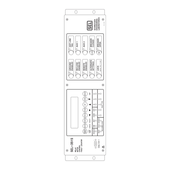
Page 45: User-Configurable Label Option For The Front Panel
User-Configurable Label Option for the Front Panel User-Configurable Label Option for the Front Panel SEL-351S relays with front-panel user-configurable labels have three (or four, depending on the model) pockets for slide-in labels: one for the target LED label, one for the breaker LEDs (for models with auxiliary {TRIP}/{CLOSE} pushbuttons), and two for the operator-control labels. - Page 46 INSERT UNDER LABEL LABEL WITH PUSH IN ALL THE WAY WITH OTHER FINGER HAND 196-0525 HERE Label Removal Tool LABEL REMOVAL TOOL Figure 2.8 SEL-351S (Horizontal) Blank Slide-In Label Set and Label Removal Tool SEL-351S Relay Instruction Manual Date Code 20080103...
- Page 47 Operator Label Control Control Label Labels Opening Opening Opening Breaker Label I1406.AI i1521A Default View Without Default View With Auxiliary {TRIP}/{CLOSE} Pushbuttons Auxiliary {TRIP}/{CLOSE} Pushbuttons Figure 2.9 SEL-351S (Vertical) With User-Configurable Default Labels Instruction Manual SEL-351S Relay Date Code 20080103...
- Page 48 FINGER 196-0525 HAND HERE Label Removal Tool LABEL REMOVAL TOOL Figure 2.10 SEL-351S (Vertical) Blank Slide-In Label Set and Label Removal Tool WARNING The SEL-351S comes with default Table 2.1 lists the various options, with explanations, available for custom labels and settings. Any change in the labeling of the SEL-351S Front Panel.
-
Page 49: Table 2.1 Options And Explanations For The User-Configurable Front-Panel Labels
Front-Panel Breaker Rear-Panel Breaker Labeling With Connectorized Rear-Panel Default Labeling Conventional Terminal Blocks Breaker Status Labeling Figure 2.11 Breaker LED Front-Panel Default Labels and Rear-Panel Labels Instruction Manual SEL-351S Relay Date Code 20080103... -
Page 50: Making Rear-Panel Connections
Wiring Harness The wiring harness includes all connectors necessary for relay installation. All connectors requiring special termination come prewired from the factory. The SEL-WA0351 Wiring Harness includes the following connectors (not prewired): ➤ (2) 8-position female plug-in connectors for output contacts OUT101–ALARM. - Page 51 These prewired connectors (and the serial port connector) are unique and may only be installed in one orientation. Model 0351SxY OUT101–OUT104 OUT105–ALARM Circuit Board-Mounted Connectors (male) IN101–IN103 IN104–IN106 Figure 2.12 SEL-351S Plug-In Connector Coding (Top View; Model 0351SxY) Instruction Manual SEL-351S Relay Date Code 20080103...
- Page 52 To determine the type of output contacts on the extra I/O board of your Model 0351S relay, refer to the part number on the serial number sticker on the relay rear panel. SEL-351S Relay Instruction Manual Date Code 20080103...
- Page 53 I/O board with standard output contacts). Optoisolated Inputs The optoisolated inputs in any of the SEL-351S models (e.g., IN102, IN207) are not polarity dependent. With nominal control voltage applied, each optoisolated input draws approximately 4 mA of current. Refer to Specifications on page 1.10...
- Page 54 Note the signal labels (VA, VB, VC, N, VS, NS) on terminals Z09–Z14. Figure 1.2 shows the internal connection for terminals VA, VB, VC, and N. Note also that VS-NS is a separate single-phase voltage input. SEL-351S Relay Instruction Manual Date Code 20080103...
- Page 55 R108 (or higher) indicates “300 V Wye/Delta.” The part number sticker on previously manufactured SEL-351S relays indicates “300 V Wye.” If older SEL-351S relays (with firmware revisions R102 through R107) are upgraded to R108 (or higher) firmware, they too can be wye connected or delta connected, provided that the voltage rating is not exceeded.
- Page 56 Synchronism Check Elements on page 3.36. SEL-351S relays with firmware revisions R107 and earlier do not have a VSCONN setting. In these relays, voltage input VS-NS operates in its traditional role of voltage input for synchronism check (as if setting VSCONN = VS).
- Page 57 VC-N (ABC rotation used in this example). For this scenario of the collapse of secondary voltage V = 0) in the broken-delta secondary, note that voltage V is 180 degrees out-of-phase with voltage V (from voltage input VA-N). Instruction Manual SEL-351S Relay Date Code 20080103...
- Page 58 To verify the correct polarity on voltage input VS-NS, perform the following test on the primary side of one of the PTs connected in broken-delta secondary (refer to Figure 2.15) and observe the resultant voltage phase angle differences: SEL-351S Relay Instruction Manual Date Code 20080103...
- Page 59 System Voltages) Serial Ports Serial PORT 1 on all the SEL-351S models is an EIA-485 port (4-wire). The serial PORT 1 plug-in connector accepts wire size AWG 24 to 12. Strip the wires 0.31 inches (8 mm) and install with a small slotted-tip screwdriver.
-
Page 60: Table 2.2 Communication Cables To Connect The Sel-351S To Other Devices
PORT 1 or PORT 2, but not both. A demodulated IRIG-B time code can be input into serial PORT 2 by connecting serial PORT 2 of the SEL-351S to an SEL-2032, SEL-2030, or SEL-2020 Communications Processor using Cable C273A. -
Page 61: Sel-351S Ac/Dc Connection Diagrams For Various Applications
). But in this residual connection example, the neutral ground and residual ground overcurrent elements operate the same because I Figure 2.17 SEL-351S Provides Overcurrent Protection and Reclosing for a Utility Distribution Feeder (Includes Fast Bus Trip Scheme) (Wye-Connected PTs) - Page 62 Although automatic reclosing is probably not needed in this example, output contact OUT102 can close the circuit breaker via initiation from various means (serial port communications, optoisolated input assertion, etc.), with desired supervision (e.g., synchronism check). Figure 2.18 SEL-351S Provides Overcurrent Protection for a Distribution Bus (Includes Fast Bus Trip Scheme) (Wye-Connected PTs) SEL-351S Relay...
- Page 63 = 3I ). But in this residual connection example, the neutral ground and residual ground overcurrent elements operate the same because I Figure 2.19 SEL-351S Provides Directional Overcurrent Protection and Reclosing for a Transmission Line (Wye-Connected PTs) Instruction Manual SEL-351S Relay...
- Page 64 Separate from Channel IN, the residual ground overcurrent elements operate from the internally derived residual current I = 3I Figure 2.20 SEL-351S Provides Directional Overcurrent Protection and Reclosing for a Transmission Line (Current-Polarization Source Connected to Channel IN) (Wye-Connected PTs) SEL-351S Relay...
- Page 65 (serial port communications, optoisolated input assertion, etc.), with desired supervision (e.g., hot bus check). For sensitive earth fault (SEF) applications, the SEL-351S should be ordered with Channel IN rated at 0.2 A or 0.05 A nominal. See current input specifications in the subsection Specifications: General on page 1.10.
- Page 66 Although automatic reclosing is probably not needed in this example, output contact OUT102 can close the circuit breaker via initiation from various means (serial port communications, optoisolated input assertion, etc.), with desired supervision (e.g., hot bus check). Figure 2.22 SEL-351S Provides Overcurrent Protection for a Transformer Bank With a Tertiary Winding (Wye-Connected PTs) SEL-351S Relay...
- Page 67 (serial port communications, optoisolated input assertion, etc.), with desired supervision. For sensitive earth fault (SEF) applications, the SEL-351S should be ordered with Channel IN rated at 0.2 A or 0.05 A nominal. See current input specifications in subsection Specifications: General on page 1.10.
- Page 68 I = 3I ). But in this residual connection example, the neutral ground and residual ground overcurrent elements operate the same because I Figure 2.24 SEL-351S Provides Dedicated Breaker Failure Protection SEL-351S Relay Instruction Manual Date Code 20080103...
- Page 69 ORDER=U (see Table 4.3–Table 4.5). Nondirectional sensitive earth fault (SEF) protection is also available. Figure 2.25 SEL-351S Provides Overcurrent Protection for a High-Impedance or Low-Impedance Grounded System (Wye-Connected PTs) Instruction Manual SEL-351S Relay...
- Page 70 Directional control for a Petersen Coil grounded system is selected with setting ORDER containing P (see Table 4.3– Table 4.5). Nondirectional sensitive earth fault (SEF) protection is also available. Figure 2.26 SEL-351S Provides Overcurrent Protection for a Petersen Coil Grounded System (Wye-Connected PTs) SEL-351S Relay Instruction Manual Date Code 20080103...
- Page 71 Directional control for an ungrounded system is selected with setting ORDER=U (see Table 4.3–Table 4.5). Nondirectional sensitive earth fault (SEF) protection is also available. Figure 2.27 SEL-351S Provides Overcurrent Protection for an Ungrounded System (Wye-Connected PTs) Instruction Manual SEL-351S Relay Date Code 20080103...
- Page 72 The polarity of voltage input VS-NS connection should be verified prior to placing the relay into service. See Polarity Check for VSCONN = 3V0 on page 2.20 for a suggested procedure. Figure 2.28 SEL-351S Provides Overcurrent Protection for an Ungrounded System (Open-Delta Connected PTs, Broken-Delta 3V0 Connection) SEL-351S Relay Instruction Manual...
- Page 73 ). But, in this residual connection example, the neutral ground and residual ground overcurrent elements operate the same because I Figure 2.29 SEL-351S Provides Overcurrent Protection and Reclosing for a Utility Distribution Feeder (Open-Delta Connected PTs and Line-to-Ground Synch-Check Connection)
-
Page 74: Figure 2.30 Sel-351S Provides Underfrequency Load Shedding, Overcurrent Protection, And
). But, in this residual connection example, the neutral ground and residual ground overcurrent elements operate the same because I Figure 2.30 SEL-351S Provides Underfrequency Load Shedding, Overcurrent Protection, and Reclosing for a Utility Distribution Feeder (Single Voltage Connection) SEL-351S Relay... -
Page 75: Figure 2.31 Sel-351S Example Wiring Diagram Using The Auxiliary {Trip}/{Close} Pushbuttons For 0351Sxxx5/6/A/B Models
Manual Close Pushbutton Open Closed Pushbutton Local Remote Close/ Auto-Reclose Remote Trips/ Protection Trips To Close Circuit — — Figure 2.31 SEL-351S Example Wiring Diagram Using the Auxiliary {TRIP}/{CLOSE} Pushbuttons for 0351Sxxx5/6/A/B Models Instruction Manual SEL-351S Relay Date Code 20080103... -
Page 76: Circuit Board Connections
ESD damage. which drawout tray needs to be removed. The main board on the SEL-351S is the top board in the chassis. If the relay has an extra I/O board it is located underneath the main board. The magnetics/auxiliary pushbutton board and power supply are mounted to the bottom of the chassis. -
Page 77: Figure 2.32 Jumper, Connector, And Major Component Locations On The Sel-351S Main Board
Step Step 16. Reenergize the relay. (On plug-in connector versions, replace the power connector at rear-panel terminals Z25 and Z26.) Figure 2.32 Jumper, Connector, and Major Component Locations on the SEL-351S Main Board Instruction Manual SEL-351S Relay Date Code 20080103... -
Page 78: Figure 2.33 Jumper, Connector, And Major Component Locations On The Sel-351Sxy Extra
2.42 Installation Circuit Board Connections Figure 2.33 Jumper, Connector, and Major Component Locations on the SEL-351SxY Extra I/O Board (Plug-In Connector Version) SEL-351S Relay Instruction Manual Date Code 20080103... -
Page 79: Figure 2.34 Jumper, Connector, And Major Component Locations On The Sel-351Sx1 Extra
Installation 2.43 Circuit Board Connections Figure 2.34 Jumper, Connector, and Major Component Locations on the SEL-351Sx1 Extra I/O Board (Screw Terminal Block Version) Instruction Manual SEL-351S Relay Date Code 20080103... -
Page 80: Figure 2.35 Jumper Locations For The 0351Sxxx5/6/A/B Model Magnetics/Auxiliary Pushbutton Board
“b” type output contacts and the other output contacts are all “a” type output contacts. This is how these jumpers are configured in a standard relay shipment. Refer to corresponding Figure 7.27–Figure 7.28 for examples of output contact operation for different output contact types. SEL-351S Relay Instruction Manual Date Code 20080103... -
Page 81: Table 2.3 Output Contact Jumpers And Corresponding Output Contacts
0351Sx1 JMP17–JMP28 Figure 2.34 “Extra Alarm” The SEL-351S has dedicated alarm output contacts (labeled ALARM—see Figure 2.2–Figure 2.6). Often more than one alarm output contact is needed Output Contact for such applications as local or remote annunciation, backup schemes, etc. -
Page 82: Table 2.6 Password And Breaker Jumper Positions For Standard Relay Shipments
Table 2.8 EIA-232 Serial Port Voltage Jumper Positions for Standard Relay Shipments EIA-232 Serial Port 2 EIA-232 Serial Port 3 Reference Figures (rear panel) (rear panel) JMP2 = OFF JMP1 = OFF Figure 2.32 SEL-351S Relay Instruction Manual Date Code 20080103... -
Page 83: Table 2.9 Jumper Positions For Breaker Open/Close Indication
To meet product safety compliance for end-use applications in North America, use an external fused rated 3 A or less in-line with the +5 Vdc source on Pin 1. SEL fiber-optic transceivers include a fuse that meets this requirement. Auxiliary {TRIP}/ The jumpers listed in Table 2.9... - Page 84 Boards. Set the relay date and time via serial batteries according to the manufacturer’s instructions. communications port or front panel (see Section 10: Serial Port Communications and Commands Section 11: Front-Panel Interface, respectively).w SEL-351S Relay Instruction Manual Date Code 20080103...
-
Page 85: Section 3: Overcurrent, Voltage, Synchronism Check, Frequency, And Power Elements
(5 A nominal phase current inputs, IA, IB, IC) ±0.01 A secondary and ±3% of setting (1 A nominal phase current inputs, IA, IB, IC) Timer: ±0.25 cycles and ±0.1% of setting Transient Overreach: ±5% of setting Instruction Manual SEL-351S Relay Date Code 20080103... -
Page 86: Figure 3.1 Levels 1-4 Phase Instantaneous Overcurrent Elements
Figure 3.1 Levels 1–4 Phase Instantaneous Overcurrent Elements Relay Enabled Word Levels Settings Bits Level 5 50P5P 5OP5 Setting E5OP ≥ 5) Level 6 50P6P 5OP6 Setting E5OP ≥ 6) (Max. Phase) Figure 3.2 Levels 5–6 Phase Instantaneous Overcurrent Elements SEL-351S Relay Instruction Manual Date Code 20080103... - Page 87 Note that single-phase overcurrent elements are not available in Levels 5 and 6 (see Figure 3.2). Ideally, set 50P1P > 50P2P > 50P3P > 50P4P so that instantaneous overcurrent elements 67P1–67P4 will display in an organized fashion in event reports (see Figure 3.3 Table 12.3). Instruction Manual SEL-351S Relay Date Code 20080103...
-
Page 88: Figure 3.3 Levels 1-4 Phase Instantaneous/Definite-Time Overcurrent Elements
(asserted to logical 1 continuously if E32 = N) OGIC OGIC Setting Torque Control 67P4TC q From Figure 3.1; w from Figure 4.24. Figure 3.3 Levels 1–4 Phase Instantaneous/Definite-Time Overcurrent Elements (With Directional Control Option) SEL-351S Relay Instruction Manual Date Code 20080103... - Page 89 E32 = then the directional control input from Figure 4.24 (Level 1) is asserted to logical 1 continuously. Then only the corresponding SEL control OGIC equation torque control setting 67P1TC has to be considered in the control of the phase instantaneous/definite-time overcurrent elements 67P1/67P1T.
-
Page 90: Figure 3.4 Combined Single-Phase Instantaneous Overcurrent Elements
Figure 3.6 show pickup and reset time curves applicable to all nondirectional instantaneous overcurrent elements in the SEL-351S Relay (60 Hz or 50 Hz relays). These times do not include output contact operating time and, thus, are accurate for determining element operation time for use in internal SEL control equations. -
Page 91: Figure 3.5 Sel-351S Nondirectional Instantaneous Overcurrent Element Pickup Time Curve
≤4: add 0.25 cycle multiples of pickup setting >4: add 0.50 cycle Maximum Minimum Applied Current (Multiples of Pickup Setting) Figure 3.5 SEL-351S Nondirectional Instantaneous Overcurrent Element Pickup Time Curve M aximum M inimum Applied Current (M ultiples of Pickup Setting) Figure 3.6 SEL-351S Nondirectional Instantaneous Overcurrent Element... - Page 92 (Channel IN current) for phase currents and substituting like settings and Relay Word bits. Table 4.3 and accompanying note for a list of the directional features available with each neutral Channel (IN) rating. SEL-351S Relay Instruction Manual Date Code 20080103...
-
Page 93: Figure 3.7 Levels 1-4 Phase-To-Phase Instantaneous Overcurrent Elements
E5OP ≥ 3) 50CA3 50PP4 50AB4 ⏐I — I ⏐ Level 4 50BC4 (Setting ⏐I — I E5OP ≥ 4) ⏐ 50CA4 ⏐I — I ⏐ Figure 3.7 Levels 1–4 Phase-to-Phase Instantaneous Overcurrent Elements Instruction Manual SEL-351S Relay Date Code 20080103... -
Page 94: Figure 3.8 Levels 1-4 Neutral Ground Instantaneous/Definite-Time Overcurrent Elements (With Directional Control Option)
(Level 4) (asserted to logical 1 continuously if E32 = N) OGIC OGIC Setting Torque Control 67N4TC From Figure 4.18. Figure 3.8 Levels 1–4 Neutral Ground Instantaneous/Definite-Time Overcurrent Elements (With Directional Control Option) SEL-351S Relay Instruction Manual Date Code 20080103... -
Page 95: Figure 3.9 Levels 5-6 Neutral Ground Instantaneous Overcurrent Elements
Two additional levels of residual ground instantaneous Instantaneous/ overcurrent elements (Levels 5 and 6) are also available. The different levels Definite-Time are enabled with the E50G enable setting, as shown in Figure 3.10 Figure 3.11. Overcurrent Elements Instruction Manual SEL-351S Relay Date Code 20080103... - Page 96 ±0.01 A secondary and ±3% of setting (1 A nominal phase current inputs, IA, IB, IC) Timer: ±0.25 cycles and ±0.1% of setting Transient Overreach: ±5% of setting Pickup and Reset Time Curves Figure 3.5 Figure 3.6. SEL-351S Relay Instruction Manual Date Code 20080103...
-
Page 97: Figure 3.10 Levels 1-4 Residual Ground Instantaneous/Definite-Time Overcurrent Elements
(Level 4) (asserted to logical 1 continuously if E32 = N) OGIC OGIC Setting Torque Control 67G4TC From Figure 4.17. Figure 3.10 Levels 1–4 Residual Ground Instantaneous/Definite-Time Overcurrent Elements (With Directional Control Option) Instruction Manual SEL-351S Relay Date Code 20080103... -
Page 98: Figure 3.11 Levels 5-6 Residual Ground Instantaneous Overcurrent Elements
0.05–20.00 A secondary (1 A nominal phase current inputs, IA, IB, IC) Setting range for definite-time settings 67Q1D–67Q4D: 0.00–16000.00 cycles, in 0.25-cycle steps Setting range for definite-time setting 67Q2SD (used in DCB logic): 0.00–60.00 cycles, in 0.25-cycle steps SEL-351S Relay Instruction Manual Date Code 20080103... -
Page 99: Figure 3.12 Levels 1-4 Negative-Sequence Instantaneous/Definite-Time Overcurrent Elements (With Directional Control Option)
E5OQ ≥ 4) (Level 4) (asserted to logical 1 continuously if E32 = N) OGIC OGIC Setting Torque Control 67Q4TC From Figure 4.23. Figure 3.12 Levels 1–4 Negative-Sequence Instantaneous/Definite-Time Overcurrent Elements (With Directional Control Option) Instruction Manual SEL-351S Relay Date Code 20080103... -
Page 100: Figure 3.13 Levels 5-6 Negative-Sequence Instantaneous Overcurrent Elements
±0.01 A secondary and ±3% of setting (1 A nominal phase current inputs, IA, IB, IC) Timer: ±0.25 cycles and ±0.1% of setting Transient Overreach: ±5% of setting Pickup and Reset Time Curves Figure 3.5 Figure 3.6. SEL-351S Relay Instruction Manual Date Code 20080103... -
Page 101: Time-Overcurrent Elements
Similarly, setting 51P2RS is not available when setting 51P2C is set to a recloser curve. control equation torque control setting (e.g., 51P1TC) cannot be set directly to OGIC logical 0. Section 9: Setting the Relay for additional time-overcurrent element setting information. Instruction Manual SEL-351S Relay Date Code 20080103... -
Page 102: Figure 3.14 Phase Time-Overcurrent Element 51P1T (With Directional Control Option)
±0.01 A secondary and ±3% of setting (1 A nominal phase current inputs, IA, IB, IC) Curve Timing: ±1.50 cycles and ±4% of cure time for currents between (and including) 2 and 30 multiples of pickup SEL-351S Relay Instruction Manual Date Code 20080103... -
Page 103: Table 3.3 Phase Time-Overcurrent Element (Maximum Phase) Logic Outputs
If the Torque Control Switch is then opened, I effectively appears as a magnitude of zero (0) to the pickup comparator: = 0 A (effective) < pickup setting 51P1P Instruction Manual SEL-351S Relay Date Code 20080103... - Page 104 Refer to Figure 3.14. control equation torque control settings (e.g., 51P1TC) cannot be set OGIC directly to logical 0. The following are setting examples of SEL control OGIC equation torque control setting 51P1TC for phase time-overcurrent element 51P1T. SEL-351S Relay...
- Page 105 I goes below 51P1P, the element starts to time to reset, emulating electromechanical reset timing. Relay Word bit 51P1R (resetting indication) = logical 1 when the element is fully reset. Instruction Manual SEL-351S Relay Date Code 20080103...
-
Page 106: Figure 3.16 Neutral Ground Time-Overcurrent Element 51N1T (With Directional Control Option)
Torque Control Setting TCN1 State Switch Position 51N1RS = Reset Timing Logical 1 Closed Electromechanical Logical 0 Open 1 Cycle From Figure 4.18. Figure 3.16 Neutral Ground Time-Overcurrent Element 51N1T (With Directional Control Option) SEL-351S Relay Instruction Manual Date Code 20080103... -
Page 107: Table 3.4 Neutral Ground Time-Overcurrent Elements Settings
(51N1C) is set to a recloser curve. In this situation, 51N1RS is effectively set to “N” internally. Similarly, setting 51N2RS is not available when setting 51N2C is set to a recloser curve. control equation torque control setting (e.g., 51N1TC) cannot be set directly to OGIC logical 0. Instruction Manual SEL-351S Relay Date Code 20080103... -
Page 108: Figure 3.18 Residual Ground Time-Overcurrent Element 51G1T (With Directional Control Option)
Torque Control Setting TCG1 State Switch Position 51G1RS = Reset Timing Logical 1 Closed Electromechanical Logical 0 Open 1 Cycle From Figure 4.17. Figure 3.18 Residual Ground Time-Overcurrent Element 51G1T (With Directional Control Option) SEL-351S Relay Instruction Manual Date Code 20080103... -
Page 109: Table 3.5 Residual Ground Time-Overcurrent Elements Settings
Similarly, setting 51G2RS is not available when setting 51G2C is set to a recloser curve. control equation torque control setting (e.g., 51G1TC) cannot be set directly to OGIC logical 0. Section 9: Setting the Relay for additional time-overcurrent element setting information. Instruction Manual SEL-351S Relay Date Code 20080103... -
Page 110: Table 3.6 Negative-Sequence Time-Overcurrent Elements Settings
(5 A nominal phase current inputs, IA, IB, IC) 0.05–3.20 A secondary (1 A nominal phase current inputs, IA, IB, IC) 51QC curve type U1–U5 (US curves), C1–C5 (IEC curves), recloser curves (Table 9.5)—see Figure 9.1–Figure 9.20 SEL-351S Relay Instruction Manual Date Code 20080103... - Page 111 ±0.01 A secondary and ±3% of setting nominal phase current inputs, IA, IB, IC (1 A Curve Timing: ±1.50 cycles and ±4% of curve time for currents between (and including) 2 and 30 multiples of pickup. Instruction Manual SEL-351S Relay Date Code 20080103...
-
Page 112: Voltage Elements
Voltage VS cannot be used for 3V0 measurement and as a synchronism check input at the same time. Voltage Table 3.8–Table 3.10 list available voltage elements and the corresponding voltage inputs and settings ranges for SEL-351S Relays (also refer to Element Settings Figure 1.2). SEL-351S Relay... -
Page 113: Table 3.8 Voltage Elements Settings And Settings Ranges (Wye-Connected Pts)
(Wye-Connected PTs) because they can assert or deassert due to noise when no signal is applied. Voltage Element Operating SEL recommends a minimum setting Pickup Setting/Range See Figure of 2.00 V. (Relay Word Bits) Voltage... -
Page 114: Table 3.10 Voltage Elements Settings And Settings Ranges (Delta-Connected Pts)
0.00–300.00 V secondary 59BC 59CA 3P59 = 59AB * 59BC * 59CA 59AB2 59PP2P 0.00–300.00 V secondary 59BC2 59CA2 59QP Figure 3.24 0.00–120.00 V secondary 59Q2 59QP2 0.00–120.00 V secondary 59V1 59V1P 0.00–170.00 V secondary SEL-351S Relay Instruction Manual Date Code 20080103... -
Page 115: Figure 3.21 Single-Phase And Three-Phase Voltage Elements (Wye-Connected Pts)
To POTT Logic Bits 27P1P 27A1 27B1 27C1 3P27 27P2P 27A2 27B2 27C2 59A1 59B1 59C1 59P1P 3P59 59A2 59B2 59C2 59P2P Figure 5.6. Figure 3.21 Single-Phase and Three-Phase Voltage Elements (Wye-Connected PTs) Instruction Manual SEL-351S Relay Date Code 20080103... -
Page 116: Figure 3.22 Phase-To-Phase And Sequence Voltage Elements (Wye-Connected Pts)
Settings/ Word Voltages Bits 27PP 27AB 27BC 27CA 59AB 59BC 59CA 59PP To POTT Logic 59N1 59N1P 59N2 59N2P 59QP 59V1 59V1P Figure 5.6. Figure 3.22 Phase-to-Phase and Sequence Voltage Elements (Wye-Connected PTs) SEL-351S Relay Instruction Manual Date Code 20080103... -
Page 117: Figure 3.23 Phase-To-Phase Voltage Elements (Delta-Connected Pts)
59CA2 59PP2P Figure 5.6. Figure 3.23 Phase-to-Phase Voltage Elements (Delta-Connected PTs) Relay Settings/ To POTT Logic Word Voltages Bits 59QP 59Q2 59Q2P 59V1 59V1P Figure 5.6. Figure 3.24 Sequence Voltage Elements (Delta-Connected PTs) Instruction Manual SEL-351S Relay Date Code 20080103... -
Page 118: Figure 3.25 Channel Vs Voltage Elements (Wye- Or Delta-Connected Pts)
(bottom of the figure). Pickup setting 59P1P is compared to the magnitudes of the individual phase voltages V , and V . The logic outputs in Figure 3.21 are the following Relay Word bits: SEL-351S Relay Instruction Manual Date Code 20080103... - Page 119 (if the settings are applicable). If the weak-infeed portion of the POTT logic is not enabled, these voltage elements can be used in any desired application. Instruction Manual SEL-351S Relay Date Code 20080103...
-
Page 120: Synchronism Check Elements
25VHI high voltage threshold 0.0–300.0 V secondary for “healthy voltage” window 25SF maximum slip frequency 0.005–0.500 Hz 25ANG1 synchronism check element 0°–80° 25A1 maximum angle 25ANG2 synchronism check element 0°–80° 25A2 maximum angle SEL-351S Relay Instruction Manual Date Code 20080103... - Page 121 SYNCP setting for this example is 270 degrees, the amount that V lags V See SEL Application Guide 2002-02, Compensate for Constant Phase Angle Difference in Synchronism Check with the SEL-351 Relay Family for more information on setting SYNCP with an angle setting. Instruction Manual...
-
Page 122: Figure 3.26 Synchronism Check Voltage Window And Slip Frequency Elements
Calculator q Frequency Calculator Slip Slip Frequency Absolute Value Frequency Element Setting Maximum Slip Frequency 25SF q See bottom of Figure 3.27; Figure 3.27. Figure 3.26 Synchronism Check Voltage Window and Slip Frequency Elements SEL-351S Relay Instruction Manual Date Code 20080103... - Page 123 Maximum Angle 1 25A1 25ANG1 Synchronism Check Element 2 Maximum Angle 2 25A2 25ANG2 Angle Difference Increasing Last Check of Setting OGIC 79CLS (w) From Figure 3.26; Figure 6.6. Figure 3.27 Synchronism Check Elements Instruction Manual SEL-351S Relay Date Code 20080103...
- Page 124 Inputs for delta-connected voltages), designated by setting SYNCP (e.g., if SYNCP = VB, then V Synchronism check voltage, from SEL-351S rear-panel voltage input VS For example, if V is designated as phase input voltage V (setting SYNCP =...
- Page 125 ACB, then setting SYNCP = 240 degrees (V constantly lags V by 240°). See the SEL Application Guide 2002-02, Compensate for Constant Phase Angle Difference in Synchronism Check with the SEL-351 Relay Family for more information on setting SYNCP with an angle setting.
- Page 126 V , and V (or V for delta) are healthy (59VP, 59VS, and 59VA asserted to logical 1) and the SEL control equation setting OGIC BSYNCH (Block Synchronism Check) is deasserted (= logical 0). The Slip Frequency Calculator output is: Slip Frequency = f –...
- Page 127 ) is faster than the system (V ). If the enable into the slip frequency calculator in Figure 3.26 is disabled (e.g., SEL setting BSYNCH asserts OGIC because the breaker closes; BSYNCH = 52A + …), then both SSLOW = logical 0 and SFAST = logical 0, regardless of slip frequency.
- Page 128 This six degree angle than six degrees. Figure 3.28 is for compensation is applied to voltage V , resulting in derived voltage V *, as general illustrative purposes only. shown in Figure 3.28. SEL-351S Relay Instruction Manual Date Code 20080103...
-
Page 129: Figure 3.28 Angle Difference Between V
. Ideally, circuit breaker closing is initiated when V * is in phase with V (Angle Difference = 0 degrees). Then when the circuit breaker main contacts finally close, V is in phase with V . But in this case, Instruction Manual SEL-351S Relay Date Code 20080103... - Page 130 V (Angle Difference = 0 degrees). There might not be enough time to wait for this to happen. Thus, the “Angle Difference = 0 degrees” restriction is eased for this scenario. SEL-351S Relay Instruction Manual Date Code 20080103...
- Page 131 6.6). Refer to the top of Figure 6.5. If timer 79CLSD is set to zero (79CLSD = 0.00), SEL control equation setting 79CLS OGIC (Reclose Supervision) is checked only once to see if it is asserted to logical 1. If it is not asserted to logical 1, the relay goes to the Lockout State.
- Page 132 (25 degrees) than for an automatic reclose (15 degrees). A single output contact (e.g., OUT102 = CLOSE) can provide the close function for both automatic reclosing and manual closing (see Figure 6.1 logic output). SEL-351S Relay Instruction Manual Date Code 20080103...
-
Page 133: Frequency Elements
Figure 3.29 Undervoltage Block for Frequency Elements (Group Setting VNOM ≠ OFF) to Frequency Element Logic (q) Setting 27B81P Relay Word Voltages Wye/Delta 27B81 VA/VAB Figure 3.31. Figure 3.30 Undervoltage Block for Frequency Elements (Group Setting VNOM = OFF) Instruction Manual SEL-351S Relay Date Code 20080103... -
Page 134: Figure 3.31 Levels 1-6 Frequency Elements
Frequency Element 6 81D6P 81D6D (Setting E81 = 6) 81D6T 81D6P ≥ NFREQ 81D6P < NFREQ Underfrequency 3.30; w 81D1–81D6 are for testing purposes only. Figure 3.29 Figure Figure 3.31 Levels 1–6 Frequency Elements SEL-351S Relay Instruction Manual Date Code 20080103... -
Page 135: Table 3.12 Frequency Elements Settings And Settings Ranges
(frequency element 1 pickup) 81D1P = 61.25 Hz. With these settings: 81D1P≥NFREQ the overfrequency part of frequency element 1 logic is enabled. 81D1 and 81D1T operate as overfrequency elements. 81D1 is used in testing only. Instruction Manual SEL-351S Relay Date Code 20080103... - Page 136 Note that all six frequency elements are controlled by the same undervoltage element (Relay Word bit 27B81). For example, when group setting VNOM ≠ OFF, and Global setting PTCONN = WYE, Relay Word bit 27B81 asserts to SEL-351S Relay Instruction Manual Date Code 20080103...
- Page 137 If frequency elements are not being used, Relay Word bit 27B81 can still be used in other logic, with voltage setting 27B81P set as desired. Enable the frequency elements (setting E81≥1) and make setting 27B81P. Apply Relay Word bit 27B81 in the desired logic scheme, using SEL control OGIC equations.
-
Page 138: Voltage Sag, Swell, And Interruption Elements (Available In Firmware Version 7)
Voltage Sag, Swell, and Interruption Elements (Available in Firmware Version 7) The SEL-351S-7 has three types of elements to detect voltage disturbances. These elements detect voltage sags, swells, and interruptions (abbreviated as “VSSI” or “SSI”). These elements are enabled by group setting ESSI = Y and controlled by the VINT, VSWELL, and VSAG settings. -
Page 139: Figure 3.33 Voltage Swell Elements
The settings ranges for the SSI thresholds are shown in Table 3.13. and Interruption The factory default settings match the Interruption, Sag, and Swell definitions in IEEE Standard 1159-1995 “Classifications of RMS Variations.” Elements Settings Instruction Manual SEL-351S Relay Date Code 20080103... -
Page 140: Table 3.13 Sag/Swell/Interruption Elements Settings (Must First Set Essi = Y)
This allows the SAG, SWELL, and INT elements voltage comparisons to be made with the reference Vbase locked at a “healthy” system voltage level. Once the disturbance is over and all of the SAGp, SWp, and INTp Relay Word bits deassert, and the FAULT SEL control equation OGIC setting deasserts, the thermal element for Vbase is unblocked. -
Page 141: Figure 3.35 Vbase Tracking Example (Three-Phase Disturbance, Wye Connected)
Vbase thermal element to remain blocked. Vbase thermal element blocking by the FAULT Relay Word bit is programmable via SEL setting FAULT. SEL control equation setting OGIC... - Page 142 SSI Reset Command After commissioning tests or other maintenance activities that have applied test voltages to the SEL-351S, the Vbase element may have locked onto a test voltage. Use the SSI R (reset) command once normal system voltages are restored on the voltage terminals. Powering up the relay automatically performs this reset.
-
Page 143: Power Elements (Available In Firmware Version 7)
The power element type settings are made in reference to the load convention: +WATTS: positive or forward real power –WATTS: negative or reverse real power +VARS: positive or forward reactive power (lagging) –VARS: negative or reverse reactive power (leading) Instruction Manual SEL-351S Relay Date Code 20080103... - Page 144 The four power element time delay settings (PWR1D–PWR4D) can be set to have no intentional delay for testing purposes. For protection applications involving the power element Relay Word bits, SEL recommends a minimum time delay setting of 5.00 cycles for general applications. The classical power calculation is a product of voltage and current, to determine the real and reactive power quantities.
- Page 145 Open-delta connected voltages (PTCONN = DELTA), with properly configured broken-delta 3V0 connection (VSCONN = 3V0): any conditions, ➤ Open-delta connected voltages, without broken-delta 3V0 connection (VSCONN = VS): balanced conditions only. Timer: ±0.25 cycles and ±0.1% of setting Instruction Manual SEL-351S Relay Date Code 20080103...
-
Page 146: Figure 3.36 Single-Phase Power Elements Logic (+Vars Example Shown)
Single-Phase VA sec Relay PWRnP Word Bits PWRnD PWRAn 40 V Sufficient Signal = 1, 2, 3, or 4 Repeat for Phases B and C Figure 3.36 Single-Phase Power Elements Logic (+VARS Example Shown) SEL-351S Relay Instruction Manual Date Code 20080103... -
Page 147: Figure 3.37 Three-Phase Power Elements Logic
Figure 3.38 Power Elements Operation in the Real/Reactive Power Plane Figure 3.36, an example is shown with setting PWRnT = +VARS. This corresponds to the settings PWR1P (pickup) and PWR1T (type) in Figure 3.38. Instruction Manual SEL-351S Relay Date Code 20080103... -
Page 148: Figure 3.39 Sel-351S(B) Provides Var Control For 9600 Kvar Capacitor Bank
Figure 3.39, if the SEL-351S(C) trips circuit breaker 52-C for a fault in the capacitor bank, then a block close signal is sent from the SEL-351S(C) to the SEL-351S(B). This prevents the SEL-351S(B) from issuing an automatic close to circuit breaker 52-C. - Page 149 These block close signals seal in when the SEL-351S(C) trips circuit breaker 52-C for a fault in the capacitor bank. Automatic closing of circuit breaker 52-C with the SEL-351S(B) can then take place only after the block close signals are reset. The exact implementation of this block close logic requires an application note beyond the scope of this discussion.
-
Page 150: Figure 3.40 Per Unit Setting Limits For Switching 9600 Kvar Capacitor Bank On- And Off-Line
9600 kVAR ≈ 1.0 per unit VARs ≈ 80.0 VA secondary (single-phase) Convert the per unit VAR levels 0.3 and –1.2 to single-phase VA (voltamperes) secondary: 0.3 • 80.0 VA secondary (single-phase) = 24.0 VA secondary (single- phase) SEL-351S Relay Instruction Manual Date Code 20080103... - Page 151 Figure 3.38). These elements are used in close logic in the SEL-351S(B) to automatically put the 9600 kVAR capacitor bank on-line. Resulting single-phase power elements PWRA2, PWRB2, and PWRC2 assert when the leading VAR level exceeds the –1.2 per unit VAR level (leading) for each respective phase (see Figure 3.40...
- Page 152 This page intentionally left blank...
-
Page 153: Section 4: Loss-Of-Potential, Load Encroachment, And Directional Element Logic
Table 4.1 LOP Logic Inputs (Sheet 1 of 2) Input Description Three-pole open condition (indicates circuit breaker open condition; see Figure 5.3). Positive-sequence voltage (V secondary). Positive-sequence current (A secondary). Zero-sequence current (A secondary). Instruction Manual SEL-351S Relay Date Code 20080103... - Page 154 (ORDER settings V, S, P, and U) are not disabled by a loss-of-potential condition on relay inputs VA, VB, and VC, because these directional elements use the 3V zero-sequence voltage that comes directly from voltage input VS, rather than the zero-sequence voltage calculated from SEL-351S Relay Instruction Manual Date Code 20080103...
- Page 155 LOP asserts to logical 1 for a loss-of-potential condition) but does not disable any voltage-based directional elements (as occurs with ELOP = Y or Y1) or enable overcurrent elements set direction forward (as occurs with ELOP = Y). Instruction Manual SEL-351S Relay Date Code 20080103...
-
Page 156: Load-Encroachment Logic
PLAR Pos.-Seq. Threshold Positive-Sequence Threshold = (Phase Channels Nominal Rating) • (0.1) (90˚) ZLIN (Load In Region) ZLOUT (Load Out Region) (180˚) (0˚) Example Settings (270˚) (—90˚) Figure 4.21. Figure 4.2 Load-Encroachment Logic SEL-351S Relay Instruction Manual Date Code 20080103... -
Page 157: Table 4.2 Load-Encroachment Settings Ranges
Convert Maximum Loads to Equivalent Secondary Impedances Start with maximum forward load: 800 MVA • (1/3) 267 MVA per phase 230 kV • (1/√3) = 132.8 kV line-to-neutral 267 MVA • (1/132.8 kV) • (1000kV/MV) = 2010 A primary Instruction Manual SEL-351S Relay Date Code 20080103... - Page 158 ° ° ° Setting PLAR = 180 (0.95) = 180 = 162 – – – ° ° ° ° Setting NLAR = 180 + cos – (0.80) = 180 + 37 = 217 SEL-351S Relay Instruction Manual Date Code 20080103...
-
Page 159: Figure 4.3 Migration Of Apparent Positive-Sequence Impedance For A Fault Condition
0 + logical 0 logical 0 Refer to Figure 3.14. To prevent phase time-overcurrent element 51P1T from OGIC ® operating for high load conditions, make the following SEL control equation torque control setting: 51P1TC = !ZLOAD*!LOP + 50P6(=NOT[ZLOAD]*NOT[LOP] + 50P6) As shown in Figure 4.2, load-encroachment logic is a positive-sequence... - Page 160 SEL-351S. Note that Application Guide AG93-10 discusses applying the load-encroachment feature to phase distance elements in the SEL-321. The SEL-351S does not have phase distance elements, but the principles and settings example are still applicable to the SEL-351S.
-
Page 161: Directional Control For Neutral Ground And Residual Ground Overcurrent Elements
Channel IN current-polarized directional element ➤ Zero-sequence voltage-polarized directional element (low- impedance grounded system) ➤ Wattmetric and incremental conductance directional elements (Petersen Coil grounded system) ➤ Zero-sequence voltage-polarized directional element (ungrounded/high-impedance grounded system) Instruction Manual SEL-351S Relay Date Code 20080103... -
Page 162: Figure 4.4 General Logic Flow Of Directional Control For Neutral Ground And Residual Ground Overcurrent Elements (Excluding Ungrounded/High-Impedance Grounded Systems)
Figure 3.18 Figure 3.19; Figure 3.10; Figure 3.16 Figure 3.17; Figure 3.8; Figure 4.5. Figure 4.4 General Logic Flow of Directional Control for Neutral Ground and Residual Ground Overcurrent Elements (Excluding Ungrounded/High-Impedance Grounded Systems) SEL-351S Relay Instruction Manual Date Code 20080103... -
Page 163: Table 4.3 Available Ground Directional Elements
See Figure 3.8, Figure 3.9, and Figure 3.18 No ground directional elements enabled All models (not accompanying settings ranges dependent on explanation. 32QGE neutral channel [IN]) 32QGE 32VE 32VE 32VE 32QGE Instruction Manual SEL-351S Relay Date Code 20080103... - Page 164 (or only) (Petersen Coil) listed choice for 32QGE 32NE the ORDER (Petersen Coil) setting 32QGE 32VE 32NE (Petersen Coil) 32VE 32NE (Petersen Coil) 32VE 32QGE 32NE (Petersen Coil) 32NE (Ungrounded/ High- Impedance) SEL-351S Relay Instruction Manual Date Code 20080103...
-
Page 165: Table 4.5 Ground Directional Element Availability By Voltage Connection Settings
The order in which these directional elements are listed in setting ORDER determines the priority in which they operate to provide Best Choice Ground Directional logic control. See the discussion on setting ORDER in the Directional Control Settings on page 4.39. Instruction Manual SEL-351S Relay Date Code 20080103... - Page 166 If the logic in Figure 4.8 (and Figure 4.12, and Figure 4.14) operates on neutral current I , then settings 50NFP and 50NRP are not adjusted, and just operate as: 50NFP base) 50NRP base) SEL-351S Relay Instruction Manual Date Code 20080103...
- Page 167 , or a measured 3V from the VS channel, typically connected to a broken-delta PT secondary. The global setting VSCONN selects the zero- sequence voltage source to be used by the affected directional elements. Instruction Manual SEL-351S Relay Date Code 20080103...
- Page 168 F32C/R32C do not propogate to directional outputs F32N/R32N, respectively, as do the wattmetric directional element outputs F32W/R32W. Incremental conductance elements are used more for alarming purposes than for controlling overcurrent elements for tripping. Incremental conductance SEL-351S Relay Instruction Manual Date Code 20080103...
- Page 169 However, this disable condition is overridden for these overcurrent elements set direction forward if setting ELOP = Y. Refer to Figure 4.1 and accompanying text for more information on loss-of- potential. Instruction Manual SEL-351S Relay Date Code 20080103...
- Page 170 In some applications, level direction settings DIR1–DIR4 are not flexible enough in assigning the desired direction for certain overcurrent elements. Subsection Directional Control Provided by Torque Control Settings on page 4.58 describes how to avoid this limitation for special cases. SEL-351S Relay Instruction Manual Date Code 20080103...
-
Page 171: Figure 4.6 Internal Enables (32Qe And 32Qge) Logic For Negative-Sequence Voltage-Polarized Directional Elements
Figure 4.1; from Figure 4.7; Figure 4.9 Figure 4.20; Figure 4.20 Figure 4.21; Figure 4.9, Table 4.3, and Table 4.4. Figure 4.6 Internal Enables (32QE and 32QGE) Logic for Negative-Sequence Voltage-Polarized Directional Elements Instruction Manual SEL-351S Relay Date Code 20080103... -
Page 172: Figure 4.7 Internal Enables (32Ve And 32Ie) Logic For Zero-Sequence Voltage-Polarized And Channel In Current-Polarized Directional Elements
Figure 4.10; Figure 4.6, Table 4.3, and Table 4.4; Figure 4.11, Figure 4.15, and Figure 4.16. Figure 4.7 Internal Enables (32VE and 32IE) Logic for Zero-Sequence Voltage-Polarized and Channel IN Current-Polarized Directional Elements SEL-351S Relay Instruction Manual Date Code 20080103... -
Page 173: Figure 4.8 Internal Enable (32Ne) Logic For Zero-Sequence Voltage-Polarized Directional Elements (Low-Impedance Grounded, Petersen Coil Grounded, And Ungrounded/High-Impedance Grounded Systems)
4.4. Figure 4.8 Internal Enable (32NE) Logic for Zero-Sequence Voltage-Polarized Directional Elements (Low-Impedance Grounded, Petersen Coil Grounded, and Ungrounded/High-Impedance Grounded Systems) Refer to the setting ideas for SEL setting E32IV, near the back of this OGIC section, especially if setting ORDER = U (ungrounded or high-impedance grounded system). -
Page 174: Figure 4.9 Negative-Sequence Voltage-Polarized Directional Element For Neutral Ground And Residual Ground Overcurrent Elements
If Z2R Setting < 0, Reverse Threshold = 1.25 • Z2R + 0.25 • Note: 1∠Z1L = One Ohm at the Positive-Sequence Line Angle From Table 4.4; Figure 4.15 Figure 4.16. Figure 4.9 Negative-Sequence Voltage-Polarized Directional Element for Neutral Ground and Residual Ground Overcurrent Elements SEL-351S Relay Instruction Manual Date Code 20080103... -
Page 175: Figure 4.10 Zero-Sequence Voltage-Polarized Directional Element
(when global settings VSCONN = VS and PTCONN = WYE) or a measured value (when global setting VSCONN = 3V0). See Zero-Sequence Voltage Sources on page 4.15. Instruction Manual SEL-351S Relay Date Code 20080103... -
Page 176: Figure 4.11 Channel In Current-Polarized Directional Element
Nominal Rating) • (Phase Channels Nominal Rating) • (0.05) Reverse Threshold: Reverse Threshold = —(Channel I Nominal Rating) • (Phase Channels Nominal Rating) • (0.05) From Table 4.4; Figure 4.15 Figure 4.16. Figure 4.11 Channel IN Current-Polarized Directional Element SEL-351S Relay Instruction Manual Date Code 20080103... -
Page 177: Figure 4.12 Zero-Sequence Voltage-Polarized Directional Element (Low-Impedance Grounded Systems)
(when Global Settings VSCONN = VS and PTCONN = WYE) or a measured value (when Global Setting VSCONN = 3V0). See Zero-Sequence Voltage Sources on page 4.15 earlier in this section. Instruction Manual SEL-351S Relay Date Code 20080103... -
Page 178: Figure 4.13 Wattmetric And Incremental Conductance Directional Elements (Petersen Coil Grounded Systems)
(when Global Settings VSCONN = VS and PTCONN = WYE) or a measured value (when Global Setting VSCONN = 3V0). See Zero-Sequence Voltage Sources on page 4.15 Directional Control Settings on page 4.39. SEL-351S Relay Instruction Manual Date Code 20080103... -
Page 179: Figure 4.14 Zero-Sequence Voltage-Polarized Directional Element (Ungrounded/High-Impedance Grounded Systems)
(when Global Settings VSCONN = VS and PTCONN = WYE) or a measured value (when Global Setting VSCONN = 3V0). See Zero-Sequence Voltage Sources on page 4.15. Instruction Manual SEL-351S Relay Date Code 20080103... -
Page 180: Figure 4.15 Routing Of Directional Elements To Residual Ground Overcurrent Elements
Figure 4.9; from Figure 4.10; from Figure 4.11; from Figure 4.12, Figure 4.13, and Figure 4.14; Figure 4.18; o from Figure 9.21. Figure 4.16 Routing of Direction Elements to Neutral Ground Overcurrent Elements SEL-351S Relay Instruction Manual Date Code 20080103... -
Page 181: Figure 4.17 Direction Forward/Reverse Logic For Residual Ground Overcurrent Elements
DIR4 = F Forward Level 4 DIR4 = N DIR4 = R Reverse Reverse 32GR From Figure 4.15; Figure 3.18 Figure 3.19; Figure 3.10. Figure 4.17 Direction Forward/Reverse Logic for Residual Ground Overcurrent Elements Instruction Manual SEL-351S Relay Date Code 20080103... -
Page 182: Figure 4.18 Direction Forward/Reverse Logic For Neutral Ground Overcurrent Elements
DIR4 = F Forward Level 4 DIR4 = N DIR4 = R Reverse Reverse 32NR From Figure 4.16; Figure 3.16 Figure 3.17; Figure 3.8. Figure 4.18 Direction Forward/Reverse Logic for Neutral Ground Overcurrent Elements SEL-351S Relay Instruction Manual Date Code 20080103... -
Page 183: Directional Control For Negative-Sequence And Phase Overcurrent Elements
Internal Enables Refer to Figure 4.6 Figure 4.19. The internal enable 32QE corresponds to the negative-sequence voltage- polarized directional element. Instruction Manual SEL-351S Relay Date Code 20080103... - Page 184 But this disable condition is overridden for the overcurrent elements set direction forward if setting ELOP = Y. Refer to Figure 4.1 and accompanying text for more information on loss-of- potential. SEL-351S Relay Instruction Manual Date Code 20080103...
- Page 185 In some applications, level direction settings DIR1–DIR4 are not flexible enough in assigning the desired direction for certain overcurrent elements. Directional Control Provided by Torque Control Settings on page 4.58 describes how to avoid this limitation for special cases. Instruction Manual SEL-351S Relay Date Code 20080103...
-
Page 186: Figure 4.20 Negative-Sequence Voltage-Polarized Directional Element For Negative-Sequence And Phase Overcurrent Elements
If Z2R Setting ≥ 0, Reverse Threshold = 0.75 • Z2R + 0.25 • If Z2R Setting < 0, Reverse Threshold = 1.25 • Z2R + 0.25 • Figure 4.22. Figure 4.20 Negative-Sequence Voltage-Polarized Directional Element for Negative-Sequence and Phase Overcurrent Elements SEL-351S Relay Instruction Manual Date Code 20080103... -
Page 187: Figure 4.21 Positive-Sequence Voltage-Polarized Directional Element For Phase Overcurrent Elements
Setting [fixed at (phase channels nominal rating) • (0.1) when enable setting ELOAD = Y] From Figure 4.2; from Figure 4.6; from Figure 4.1; Figure 4.22. Figure 4.21 Positive-Sequence Voltage-Polarized Directional Element for Phase Overcurrent Elements Instruction Manual SEL-351S Relay Date Code 20080103... -
Page 188: Figure 4.22 Routing Of Directional Elements To Negative-Sequence And Phase Overcurrent Elements
R32Q (Reverse) 32PF F32P (Forward) 32PR R32P (Reverse) From Figure 4.1; from Figure 4.20; from Figure 4.21; Figure 4.23; Figure 4.24. Figure 4.22 Routing of Directional Elements to Negative-Sequence and Phase Overcurrent Elements SEL-351S Relay Instruction Manual Date Code 20080103... -
Page 189: Figure 4.23 Direction Forward/Reverse Logic For Negative-Sequence Overcurrent Elements
DIR4 = F Forward Level 4 DIR4 = N Relay Word DIR4 = R Reverse Reverse 32QR From Figure 4.22; Figure 3.20; Figure 3.12. Figure 4.23 Direction Forward/Reverse Logic for Negative-Sequence Overcurrent Elements Instruction Manual SEL-351S Relay Date Code 20080103... -
Page 190: Figure 4.24 Direction Forward/Reverse Logic For Phase Overcurrent Elements
DIR4 = F Forward Level 4 DIR4 = N Relay Word DIR4 = R Reverse Reverse 32PR From Figure 4.22; Figure 3.14 Figure 3.15; Figure 3.3. Figure 4.24 Direction Forward/Reverse Logic for Phase Overcurrent Elements SEL-351S Relay Instruction Manual Date Code 20080103... -
Page 191: Directional Control Settings
E32 = AUTO. They have to be set by the user, whether setting E32 = AUTO or Y. These settings are: DIR1, DIR2, DIR3, DIR4, ORDER, 50P32P, 50NFP, 50NRP, a0N, 59RES, 32WFP, 32WRP, 32WD, and E32IV (E32IV is a SEL OGIC setting) All these settings are explained in detail in the remainder of this subsection. -
Page 192: Table 4.6 Directional Control Settings Not Made For Particular Conditions
(Figure 3.8) 67G3T (Figure 3.10) 67Q3T (Figure 3.12) DIR4 67P4 (Figure 3.3) 67N4 (Figure 3.8) 67G4 (Figure 3.10) 67Q4 (Figure 3.12) 67P4T (Figure 3.3) 67N4T (Figure 3.8) 67G4T (Figure 3.10) 67Q4T (Figure 3.12) SEL-351S Relay Instruction Manual Date Code 20080103... - Page 193 DIRn (n = 1–4) settings to be directionally controlled (see Figure 4.17 Figure 4.18). Another example, if setting: ORDER = Instruction Manual SEL-351S Relay Date Code 20080103...
- Page 194 ORDER = QP or ORDER = QVP (see Table 4.4). Then, the residual ground elements (Figure 4.17) are controlled by the directional control logic and provide directional protection for higher ground fault currents. SEL-351S Relay Instruction Manual Date Code 20080103...
-
Page 195: Table 4.8 Z Constant For Z2R Setting
Z0R. The same general approach outlined for deriving settings Z0F and Z0R can also be applied to deriving settings Z2F and Z2R in the negative-sequence impedance network, though the preceding method of automatically making settings Z2F and Z2R usually suffices. Instruction Manual SEL-351S Relay Date Code 20080103... - Page 196 For setting a2 = 0.1, the negative-sequence current (I ) magnitude has to be greater than 1/10 of the positive-sequence current (I ) magnitude in order for the negative-sequence voltage-polarized directional elements to be enabled | > 0.1 • |I SEL-351S Relay Instruction Manual Date Code 20080103...
- Page 197 1/5 of the zero-sequence current (I ) magnitude in order for the negative-sequence voltage-polarized directional elements to be enabled 0.2 • |I |). Again, this presumes at least one of the internal enables 32VE or 32IE is asserted. Instruction Manual SEL-351S Relay Date Code 20080103...
- Page 198 The a0 factor increases the security of the zero-sequence voltage-polarized and channel IN current-polarized directional elements. This factor keeps the elements from operating for zero-sequence current (system unbalance), which circulates due to line asymmetries, CT saturation during three-phase faults, etc. SEL-351S Relay Instruction Manual Date Code 20080103...
- Page 199 If enable setting E32 = Y, settings Z0F and Z0R (zero-sequence impedance values) are calculated by the user and entered by the user, but setting Z0R must be greater in value than setting Z0F by 0.1 Ω secondary. Instruction Manual SEL-351S Relay Date Code 20080103...
-
Page 200: Table 4.9 Z Constant For Z0R Setting
Deriving Z0F and Z0R Settings when needed (effectively, Z0F•CTRN/CTR and Z0R•CTRN/ Figure 4.25 shows the voltage and current polarity for an SEL-351S in a zero- CTR). See Internal Enables on page 4.14. sequence impedance network (the same approach can be instructive for negative-sequence impedance analysis, too). -
Page 201: Figure 4.25 Zero-Sequence Impedance Network And Relay Polarity
0.2 A nominal neutral channel (IN), then settings 50NFP and 50NRP are not made or displayed. Instruction Manual SEL-351S Relay Date Code 20080103... - Page 202 The a0N factor increases the security of the zero-sequence voltage-polarized directional elements: low-impedance grounded or ungrounded/high- impedance grounded. It keeps the elements from operating for zero-sequence current (system unbalance), which circulates due to line asymmetries, etc. SEL-351S Relay Instruction Manual Date Code 20080103...
- Page 203 VS-NS input signal. The 32WFP and 32WRP settings must be entered on the same secondary base as the voltage terminals VA, VB, and VC. See Settings Considerations for Petersen Coil Grounded Systems on page 4.54 for an example. Instruction Manual SEL-351S Relay Date Code 20080103...
-
Page 204: Figure 4.27 Zero-Sequence Impedance Network For Ground Fault On Feeder 1
Zero-Sequence Reference Bus Petersen Coil Feeder 2 Feeder n Transformer Bank 0(2) Relay 2 Relay 1 0(1) Feeder 1 =0 (Tuned System) Figure 4.27 Zero-Sequence Impedance Network for Ground Fault on Feeder 1 SEL-351S Relay Instruction Manual Date Code 20080103... -
Page 205: Figure 4.28 Wattmetric Element Operation For Ground Fault On Feeder 1
32WFP and 32WRP in the wattmetric plane (setting 32WFP is put on the “negative” side of the wattmetric plane: i.e., “–32WFP”; see Figure 4.13). Instruction Manual SEL-351S Relay Date Code 20080103... - Page 206 3V quantity, as shown in Table 4.10. Thus, when the zero-sequence voltage pickup for the wattmetric element is known in terms of the system primary voltage level, the required calculation for setting SEL-351S Relay Instruction Manual Date Code 20080103...
- Page 207 (secondary), then the setting value must be scaled by PTRS/PTR prior to entry. This pre-scaling makes the 32WFP and 32WRP settings match the scaling the relay does when it converts the VS value into the VA, VB, VC voltage base. Instruction Manual SEL-351S Relay Date Code 20080103...
-
Page 208: Table 4.10 Affect Of Global Settings Vsconn And Ptconn On Petersen Coil Directional Elements
IN current-polarized directional elements for directional control of neutral ground and residual ground overcurrent elements. For most applications, set E32IV directly to logical 1: 1 (numeral 1) E32IV = SEL-351S Relay Instruction Manual Date Code 20080103... - Page 209 E32IV should be OGIC deasserted to logical 0. In this example, connect a circuit breaker auxiliary contact from the isolating circuit breaker to the SEL-351S: E32IV = IN106 (52a connected to optoisolated input IN106) Almost any desired control can be set in SEL...
-
Page 210: Directional Control Provided By Torque Control Settings
51G1TC = 32GF (direction forward; see Figure 3.18) This is just one example of using SEL control equation torque control OGIC settings to make overcurrent elements directional (forward or reverse) or nondirectional. This example shows only Level 1 overcurrent elements (controlled by level direction setting DIR1). - Page 211 Section 5 Trip and Target Logic Trip Logic OGIC ® The trip logic in Figure 5.1 provides flexible tripping with SEL control equation settings: TRCOMM—Communications-Assisted Trip Conditions. Setting TRCOMM is supervised by communications-assisted trip logic. See Communications-Assisted Trip Logic—General Overview on page 5.11...
-
Page 212: Section 5: Trip And Target Logic Trip Logic
OR-1 gate. The output of OR-1 gate asserts Relay Word bit TRIP to logical 1, regardless of other trip logic conditions. It also is routed into the Minimum Trip Duration Timer (setting TDURD). SEL-351S Relay Instruction Manual Date Code 20080103... -
Page 213: Figure 5.2 Minimum Trip Duration Timer Operation (See Bottom Of Figure 5.1)
Use these to force the TRIP Relay Word bit to logical 0 if test conditions are such that setting ULTR does not assert to logical 1 to automatically deassert the TRIP Relay Word bit instead. Instruction Manual SEL-351S Relay Date Code 20080103... - Page 214 OGIC Setting TR) gate and follows into the “seal-in and unlatch” logic for Relay Word bit TRIP. The factory settings for the trip logic SEL control equation settings are: OGIC TR = 51P1T + 51G1T + 67P1 + PB10 + OC (trip conditions)
- Page 215 TRIP Relay Word bit deasserts to logical 0. Program an Output In the factory settings, the resultant of the trip logic in Figure 5.1 is routed to output contact OUT101 with the following SEL control equation setting: OGIC Contact for Tripping TRIP OUT101 = If more than one TRIP output contact is needed, program other output contacts with the TRIP Relay Word bit.
- Page 216 Trip and Target Logic Trip Logic TRIP Used in Other Besides operating a trip output contact (e.g., OUT101 = TRIP), the TRIP Relay Word bit is used in a number of other factory-default SEL control OGIC Settings equations settings: TRIP + … unlatch close—see ULCL = Figure 6.3...
- Page 217 (51G2) to the event report trigger conditions setting (ER = … + /51G2). A rising edge operator (/) is added on front of the element (see Appendix G: Setting SEL OGIC Control Equations for more explanation on rising edge operators).
-
Page 218: Switch-Onto-Fault (Sotf) Trip Logic
Refer to the switch-onto-fault trip logic in Figure 5.1 (middle of figure). The SOTF trip logic permits tripping if both the following occur: ➤ An element asserts in SEL control equation trip setting OGIC TRSOTF ➤ Relay Word bit SOTFE is asserted to logical 1 Relay Word bit SOTFE (the output of the SOTF logic) provides the effective time window for an element in trip setting TRSOTF (e.g., TRSOTF = 50P2) to... - Page 219 3PO = logical 0 (circuit breaker closed) Determining Three-Pole Open Condition Without Circuit Breaker Auxiliary Contact If a circuit breaker auxiliary contact is not connected to the SEL-351S Relay, control equation setting 52A is set: OGIC 0 (numeral 0)
- Page 220 Circuit breaker closure is detected by monitoring the dc close bus. This is accomplished by wiring an optoisolated input on the SEL-351S (e.g., IN105) to the dc close bus. When a manual close or automatic reclosure occurs, optoisolated input IN105 is energized.
-
Page 221: Communications-Assisted Trip Logic-General Overview
Trip and Target Logic 5.11 Communications-Assisted Trip Logic—General Overview Communications-Assisted Trip Logic— General Overview The SEL-351S includes communications-assisted tripping schemes that provide unit-protection for transmission lines with the help of communications. No external coordination devices are required. Level 1 (1) Level 3 (1) - Page 222 POTT, PUTT, DCUB, and DCB communications-assisted tripping schemes are explained in subsections that follow. Trip Setting TRCOMM The POTT, PUTT, DCUB, and DCB tripping schemes use SEL control OGIC equation trip setting TRCOMM for those tripping elements that are supervised...
- Page 223 Function IN102 = PT PT1 = IN102 (received permissive trip) In the above SEL-351S setting example, Relay Word bit IN102 is set in the PT1 SEL control equation. Optoisolated input IN102 is wired to a OGIC communications equipment receiver output contact. Relay Word bit IN102 can also be used in other SEL control equation in the SEL-351S.
- Page 224 The SEL-321 handles trip unlatching with setting TULO. The SEL-351S handles trip unlatching with SEL control equation setting ULTR. OGIC The SEL-321 has single-pole trip logic. The SEL-351S does not have single- pole trip logic. ITS ® Using M The M...
-
Page 225: Permissive Overreaching Transfer Trip (Pott) Logic
Provides a secure means of tripping for weak- and/or zero- infeed line terminals Use Existing SEL-321 Use the existing SEL-321 POTT application guide (AG95-29) to help set up the SEL-351S in a POTT scheme (see preceding subsection Communications- POTT Application Assisted Trip Logic—General Overview on page 5.11... -
Page 226: Figure 5.5 Permissive Input Logic Routing To Pott Logic
Setting ECOMM = DCUB2 Figure 5.6. Figure 5.5 Permissive Input Logic Routing to POTT Logic Also note that SEL control equation setting PT1 in Figure 5.7 is routed to OGIC control Relay Word bit PTRX if enable setting ECOMM = POTT. Relay Word... - Page 227 In a three-terminal line scheme, output contact OUT107 is set the same as OUT105 (see Figure 5.9): OUT107 = EKEY—Echo Key Permissive Trip Permissive trip signal keyed by Echo logic (used in testing). Instruction Manual SEL-351S Relay Date Code 20080103...
-
Page 228: Figure 5.6 Pott Logic
5.18 Trip and Target Logic Permissive Overreaching Transfer Trip (POTT) Logic Figure 4.1; Figure 5.5; Table 3.8; Table 3.10; Figure 5.1. Figure 5.6 POTT Logic SEL-351S Relay Instruction Manual Date Code 20080103... -
Page 229: Figure 5.7 Permissive Input Logic Routing To Trip Logic
Depending on the installation, perhaps one output contact (e.g., OUT105 = KEY) could be connected in parallel to both transmitter inputs (TX) 5.9. Then output contact OUT107 on the communication equipment in Figure can be used for another function. Instruction Manual SEL-351S Relay Date Code 20080103... -
Page 230: Figure 5.8 Sel-351S Connections To Communications Equipment For A Two-Terminal Line Pott Scheme
OUT105 (Partial) IN104 OUT105 = KEY PT1 = IN104 To / From Remote Terminal (—) Figure 5.8 SEL-351S Connections to Communications Equipment for a Two-Terminal Line POTT Scheme SEL-351 OUT105 OUT107 (partial) IN104 IN106 OUT105 = KEY PT1 = IN104 * IN106... -
Page 231: Directional Comparison Unblocking (Dcub) Logic
PT1, PT2—Received Permissive Trip Signal(s) In two-terminal line DCUB applications (setting ECOMM = DCUB1), a permissive trip signal is received from one remote terminal. One optoisolated input on the SEL-351S (e.g., input IN104) is driven by a communications equipment receiver output (see Figure 5.12). - Page 232 LOG1, LOG2—Loss-of-Guard Signal(s) In two-terminal line DCUB applications (setting ECOMM = DCUB1), a loss- of-guard signal is received from one remote terminal. One optoisolated input on the SEL-351S (e.g., input IN105) is driven by a communications equipment receiver output (see Figure 5.12).
- Page 233 Relay Word bit UBB, depending on enable setting ECOMM = DCUB1 or DCUB2. Relay Word bit UBB is the unblock block input into the trip logic in Figure 5.1. When UBB asserts to logical 1, tripping is blocked. Instruction Manual SEL-351S Relay Date Code 20080103...
-
Page 234: Figure 5.10 Dcub Logic
5.24 Trip and Target Logic Directional Comparison Unblocking (DCUB) Logic Figure 5.11; Figure 5.7. Figure 5.10 DCUB Logic SEL-351S Relay Instruction Manual Date Code 20080103... -
Page 235: Figure 5.11 Unblocking Block Logic Routing To Trip Logic
OUT105 = KEY LOG1 = IN105 To / From TRIP GUARD Remote (RX) (RX) Terminal (—) Figure 5.12 SEL-351S Connections to Communications Equipment for a Two-Terminal Line DCUB Scheme (Setting ECOMM = DCUB1) Instruction Manual SEL-351S Relay Date Code 20080103... -
Page 236: Figure 5.13 Sel-351S Connections To Communications Equipment For A Three-Terminal Line Dcub Scheme (Setting Ecomm = Dcub2)
To / From TRIP GUARD TRIP GUARD Remote Remote (RX) (RX) (RX) (RX) Terminal 1 Terminal 2 (—) Figure 5.13 SEL-351S Connections to Communications Equipment for a Three-Terminal Line DCUB Scheme (Setting ECOMM = DCUB2) SEL-351S Relay Instruction Manual Date Code 20080103... -
Page 237: Directional Comparison Blocking (Dcb) Logic
➤ Extends the received block signal by a settable time. Use Existing SEL-321 Use the existing SEL-321 DCB application guide (AG93-06) to help set up the SEL-351S in a DCB scheme (see preceding subsection Communications- DCB Application Assisted Trip Logic—General Overview on page 5.11... - Page 238 See Output Contacts on page 7.32 for more information on output contacts. DSTRT—Directional Carrier Start Program an output contact for directional carrier start. For example, SEL OGIC control equation setting OUT105 is set: DSTRT OUT105 = Output contact OUT105 drives a communications equipment transmitter input...
-
Page 239: Figure 5.14 Dcb Logic
Depending on the installation, perhaps one output contact (e.g., OUT106 = STOP) can be connected in parallel to both STOP inputs on the communication equipment in Figure 5.16. Then output contact OUT208 can be used for another function. Instruction Manual SEL-351S Relay Date Code 20080103... -
Page 240: Figure 5.15 Sel-351S Connections To Communications Equipment For A Two-Terminal Line Dcb
RX (receive) output Figure 5.16 contacts from each remote terminal connected to separate inputs IN104 and IN106 on the SEL-351S. The inputs operate as block trip receive inputs for the two remote terminals and are used in the SEL control equation setting:... -
Page 241: Figure 5.16 Sel-351S Connections To Communications Equipment For A Three-Terminal Line Dcb
To / From 85CO Remote Remote START STOP (RX) START STOP (RX) Terminal 2 Terminal 1 (TX) (TX) (TX) (TX) (—) Figure 5.16 SEL-351S Connections to Communications Equipment for a Three-Terminal Line DCB Scheme Instruction Manual SEL-351S Relay Date Code 20080103... -
Page 242: Front-Panel Target Leds
LEDs. The functions and associated settings for these target LEDs are given in Table 5.1. Table 5.1 SEL-351S Front-Panel Target LED Definitions and Settings LED Front- LED Logic Latch In On Panel Input (SEL... -
Page 243: Figure 5.17 Programmable Front-Panel Target Led Logic
LEDs A, B, and C always latch in on trip, if the corresponding phase is involved with the fault. LEDs A, B, and C reset (unlatch) similar to the other target LEDs set to latch in on trip. SEL control equation FAULT has to be picked up... - Page 244 5.37. OGIC LED14 (COMM) and LED15 (SOTF) Refer to the top part of Figure 5.1. If overcurrent elements are set in SEL OGIC control equations TRCOMM or TRSOTF and a trip results from either associated logic path: ➤ Relay Word bit COMMT asserts (LED14 = COMMT) ➤...
- Page 245 ➤ LED16 = 67P1 ➤ LED17 = 51P1T + 51G1T LED18 (81) If frequency element 81D1T is set to trip (e.g., SEL control equation TR OGIC = … + 81D1T) and a trip results from 81D1T: ➤ LED18 = 81D1T then LED18 (81) illuminates at the rising edge of trip.
-
Page 246: Figure 5.18 Seal-In Of Breaker Failure Occurrence For Message Display
{TARGET RESET} pushbutton (Relay Word bit TRGTR pulses to logical 1, unlatching SV8 and in turn deasserting DP3). Thus, front-panel rotating default displays can be easily reset along with the front-panel targets by pushing the {TARGET RESET} pushbutton. SEL-351S Relay Instruction Manual Date Code 20080103... - Page 247 Maximum/Minimum Metering on page 8.30. ➤ Voltage Sag, Swell Interruption elements—FAULT is used to suspend the calculation of Vbase. See subsection Voltage Sag, Swell, and Interruption Elements (Available in Firmware Version 7) on page 3.54. Instruction Manual SEL-351S Relay Date Code 20080103...
- Page 248 This page intentionally left blank...
- Page 249 (e.g., manual close initiation via serial port or optoisolated inputs). If automatic reclosing is not needed, but the SEL-351S Relay is to close the circuit breaker for other close conditions (e.g., manual close initiation via serial port or optoisolated inputs), then this is the only OGIC ®...
-
Page 250: Section 6: Close And Reclose Logic Close Logic
Close and Reclose Logic Close Logic Close Logic The close logic in Figure 6.1 provides flexible circuit breaker closing/ automatic reclosing with SEL control equation settings: OGIC (breaker status—also see Figure 6.4) (close conditions other than automatic reclosing—also Figure 6.2) - Page 251 ➤ The Close Failure Timer times out (Relay Word bit CF = 1) The Close Failure Timer is inoperative if setting CFD = OFF. Factory Settings The factory settings for the close logic SEL control equation settings are: OGIC IN101...
-
Page 252: Figure 6.2 Close Conditions-Other Than Auto-Reclosing
{LOCK} operator control is ON or the {HOT LINE TAG} operator control is ON. The logic allows the CLOSE command and auto-reclosing to still proceed with the {LOCK} operator control ON. SEL-351S Relay Instruction Manual Date Code 20080103... -
Page 253: Figure 6.3 Unlatch Close Conditions
!IN101 52b auxiliary contact wired to input IN101 52A = then if breaker status is used in other SEL control equations, it can be OGIC entered as 52A—the user does not have to enter IN101 (for a 52a) or !IN101 (for a 52b). -
Page 254: Figure 6.4 Breaker Status Determination
Figure 6.4 Breaker Status Determination Program an Output In the factory settings, the resultant of the close logic in Figure 6.1 is routed to output contact OUT102 with the following SEL control equation: OGIC Contact for Closing CLOSE OUT102 = Output Contacts on page 7.32... -
Page 255: Reclose Supervision Logic
Reclose Supervision Reclose Supervision condition, Limit Timer times out. Reclose Initiate 79RI 79CLS, to assert to logical 1) Figure 6.1. Figure 6.5 Reclose Supervision Logic (Following Open-interval Time-Out) Instruction Manual SEL-351S Relay Date Code 20080103... -
Page 256: Figure 6.6 Reclose Supervision Limit Timer Operation (Refer To Bottom Of Figure 6.5)
79CLSD times out. Figure 6.6 Reclose Supervision Limit Timer Operation (Refer to Bottom of Figure 6.5) Settings and General Figure 6.5 contains the following SEL control equation setting: OGIC Operation 79CLS (reclose supervision conditions—checked after reclosing relay open-interval time-out) and setting:... - Page 257 Reclose Supervision Logic With this setting, the logic in the top of Figure 6.5 is operative. When an open interval times out, the SEL control equation reclose supervision setting OGIC 79CLS is checked just once. If 79CLS is asserted to logical 1 at the instant of an open-interval time-out,...
- Page 258 79CLS is checked indefinitely until one of the other above unlatch conditions comes true. The unlatching of the sealed-in reclosing relay open-interval time-out condition by the assertion of SEL control equation setting 79CLS OGIC indicates successful propagation of a reclosing relay open-interval time-out...
-
Page 259: Figure 6.7 Sel-351S Relays Installed At Both Ends Of A Transmission Line In A High-Speed Reclose
6.7. Example 1 SEL-351S relays are installed at both ends of a transmission line in a high- speed reclose scheme. After both circuit breakers open for a transmission line fault, the SEL-351S(1) recloses circuit breaker 52/1 first, followed by the SEL-351S(2) reclosing circuit breaker 52/2, after a synchronism check across circuit breaker 52/2. - Page 260 0 (numeral 0) The SEL-351S(2) starts open-interval timing after circuit breaker 52/1 at the remote end has reenergized the line. The SEL-351S(2) has to see Bus 2 hot, transmission line hot, and in synchronism across open circuit breaker 52/2 for open-interval timing to begin.
- Page 261 If the reclosing relay increments to the last shot value (no more open intervals left; see Figure 6.9 Table 6.3), the reclosing relay is then driven to the Lockout State. Instruction Manual SEL-351S Relay Date Code 20080103...
-
Page 262: Reclosing Relay
Reclosing Relay Reclosing Relay Note that input: Reclosing Relay Open-interval Time-Out Figure 6.5 is the logic input that is qualified by SEL control equation OGIC setting 79CLS, and then propagated on to the close logic in Figure 6.1 automatically reclose a circuit breaker. The explanation that follows in this... -
Page 263: Table 6.1 Relay Word Bit And Front-Panel Correspondence To Reclosing Relay States
States and General Operation Reset State The circuit breaker has been closed for a qualifying reset time. The SEL-351 is ready to go through an automatic reclosing sequence in the reclose cycle state if the circuit breaker trips open and reclose initiation is successful. - Page 264 The shot counter is equal to or greater than the last shot at time of reclose initiation (e.g., all automatic reclosing attempts are unsuccessful—see Figure 6.9). ➤ Reclose initiation is unsuccessful because of SEL control OGIC equation setting 79RIS [see Reclose Initiate and Reclose Initiate Supervision Settings (79RI and 79RIS, Respectively) on page 6.21].
-
Page 265: Table 6.2 Reclosing Relay Timer Settings And Setting Ranges
For example, if 52A = IN101, a 52a circuit breaker auxiliary contact is connected to input IN101. If the reclosing relay does not exist, the close logic still operates, allowing closing to take place via SEL control equation OGIC setting CL (close conditions, other than automatic reclosing). -
Page 266: Figure 6.9 Example Reclosing Sequence From Reset To Lockout
In the Figure 6.9 example, two set open-interval times precede open-interval 3 time, which is set to zero (79OI3 = 0.00): 30.00 79OI1 = SEL-351S Relay Instruction Manual Date Code 20080103... - Page 267 Setting 79RSLD: Qualifies closures when the relay is in the Lockout State. These closures are usually manual closures. These manual closures can originate external to the relay, via the CLOSE command, or via the SEL control OGIC equation setting CL (see Figure 6.1).
-
Page 268: Table 6.3 Shot Counter Correspondence To Relay Word Bits And Open-Interval Times
Relay Word bit asserts to logical 1 (e.g., SH2 = logical 1). The shot counter also increments for sequence coordination operation. The shot counter can increment beyond the last shot for sequence coordination [see Sequence Coordination Setting (79SEQ) on page 6.28]. SEL-351S Relay Instruction Manual Date Code 20080103... - Page 269 SEL-351S to successfully initiate reclosing and start timing on the first open-interval. The SEL-351S is not yet in the reclose cycle state (79CY = logical 0) at the instant of the first trip.
- Page 270 Close and Reclose Logic Reclosing Relay If a flashover occurs in a circuit breaker tank during an open-interval (circuit breaker open and the SEL-351S calls for a trip), the SEL-351S goes immediately to lockout. Additional Settings Example The preceding settings example initiates open-interval timing on rising edge of the TRIP Relay Word bit.
- Page 271 79RI [reclose initiation] discussion). Then the drive-to-lockout condition overlaps reclose initiation and the SEL-351S stays in lockout after the breaker trips open. When 79DLS = logical 1, the reclosing relay goes to the last shot, if the shot...
-
Page 272: Figure 6.10 Factory-Default Drive-To-Lockout Logic
If 79SKP = logical 1 at the instant of successful reclose initiation (see Settings (79SKP and preceding discussion on settings 79RI and 79RIS), the relay increments the 79STL, Respectively) shot counter to the next shot and then loads the open-interval time SEL-351S Relay Instruction Manual Date Code 20080103... -
Page 273: Table 6.5 Example Open-Interval Time Settings
(setting 79OI1) is skipped, and the relay times on the open-interval 2 time (setting 79OI2) instead. Table 6.5 Example Open-Interval Time Settings Corresponding Corresponding Open-Interval Shot Relay Word Bit Open Interval Time Setting 79OI1 30 cycles 79OI2 600 cycles Instruction Manual SEL-351S Relay Date Code 20080103... -
Page 274: Figure 6.11 Reclose Blocking For Islanded Generator
79SKP = logical 0, regardless of Relay Word bit 50P2. Additional Settings Example 2 If the SEL-351S is used on a feeder with a line-side independent power producer (cogenerator), the utility should not reclose into a line still energized by an islanded generator. - Page 275 Additional Settings Example 2 If the block reset timing setting is: 51P1 + 51G1 79BRS = then reset timing is blocked if time-overcurrent pickup 51P1 or 51G1 is picked up, regardless of the reclosing relay state. Instruction Manual SEL-351S Relay Date Code 20080103...
- Page 276 (e.g., line recloser—see Figure 6.12) has operated to clear a fault. Incrementing the shot counter keeps the SEL-351S “in step” with the downstream device, as is shown in the following Additional Settings Example 1 on page 6.28 Additional Settings Example 2 on page 6.30.
-
Page 277: Figure 6.13 Operation Of Sel-351S Shot Counter For Sequence Coordination With Line Recloser
Fault occurs beyond line recloser; w fault cleared by line recloser fast curve; e line recloser recloses into fault; r fault cleared by line recloser slow curve. Figure 6.13 Operation of SEL-351S Shot Counter for Sequence Coordination With Line Recloser (Additional Settings Example 1) - Page 278 6.30 Close and Reclose Logic Reclosing Relay If the SEL-351S is in the Reset State (79RS = logical 1) and then a permanent fault beyond the line recloser occurs (fault current I Figure 6.12), the line recloser fast curve operates to clear the fault. The SEL-351S also sees the fault.
- Page 279 Refer to Figure 6.14. If the SEL-351S is in the Reset State (79RS = logical 0) with the shot counter reset (shot = 0; SH0 = logical 1) and then a permanent fault beyond the line recloser occurs (fault current I Figure 6.12), the line recloser fast curve...
- Page 280 This page intentionally left blank...
- Page 281 The above items are all the logic input/output of the relay. They are combined OGIC ® with the overcurrent, voltage, frequency, and reclosing elements in SEL control equation settings to realize numerous protection and control schemes. Relay Word bits and SEL...
-
Page 282: Optoisolated Inputs
(e.g., optoisolated inputs IN101–IN106 in Figure 7.1) for the different SEL-351S Relay models. The figures show examples of energized and de- energized optoisolated inputs and corresponding Relay Word bit states. To assert an input, apply rated control voltage to the appropriate terminal pair (see Figure 1.2–Figure 1.4... -
Page 283: Figure 7.2 Example Operation Of Optoisolated Inputs In201-In208-Extra I/O Board
Only a few applications (e.g., communications-assisted tripping schemes) might require input pickup/dropout debounce timers set less than 1/4-cycle [e.g., if setting IN105D = 0.13, internally the timer runs at the nearest 1/16-cycle: 2/16-cycles (2/16 = 0.1250)]. Instruction Manual SEL-351S Relay Date Code 20080103... -
Page 284: Figure 7.3 Circuit Breaker Auxiliary Contact And Reclose Enable Switch Connected To Optoisolated
Note that Figure 7.3 corresponds to Figure 7.29. Input IN101 Relay Word bit IN101 is used in the factory settings for the SEL control OGIC equation circuit breaker status setting: 52A = IN101 Connect input IN101 to a 52a circuit breaker auxiliary contact. - Page 285 Inputs, Outputs, Timers, and Other Control Logic Optoisolated Inputs Input IN102 Relay Word bit IN102 is used in this example for the SEL control OGIC equation drive-to-lockout setting: !IN102 + ... [=NOT(IN102) + ...] 79DTL = Connect input IN102 to a reclose enable switch.
-
Page 286: Local Control Switches
Relay Word bit LBn (n = 1–16), called a local bit. The local control switch logic in Figure 7.4 repeats for each local bit LB1–LB16. Use these local bits in SEL control OGIC equations. For a given local control switch, the local control switch positions are enabled by making corresponding label settings. -
Page 287: Table 7.2 Correspondence Between Local Control Switch Types And Required Label Settings
Disable local control switches by “nulling out” all the label settings for that switch (see Section 9: Setting the Relay). The local bit associated with this disabled local control switch is then fixed at logical 0. Instruction Manual SEL-351S Relay Date Code 20080103... -
Page 288: Figure 7.8 Configured Manual Trip Switch Drives Local Bit Lb3
Inputs, Outputs, Timers, and Other Control Logic Local Control Switches Settings Examples Local bits LB3 and LB4 are used in a few example SEL control equation OGIC settings for manual trip and close functions. Their corresponding local control switch position labels are set to configure the switches as OFF/... - Page 289 0, regardless of the local bit state before the settings change. If a local control switch is made newly operable because of a settings change (i.e., the corresponding label settings are set), the corresponding local bit starts out at logical 0. Instruction Manual SEL-351S Relay Date Code 20080103...
-
Page 290: Remote Control Switches
The outputs of the remote control switches in Figure 7.10 are Relay Word bits RBn (n = 1 to 16), called remote bits. Use these remote bits in SEL OGIC control equations. Any given remote control switch can be put in one of the following three... - Page 291 CON Command (Control Remote Bit) on page 10.40. Appendix G: Setting SEL Control Equations for more details on OGIC using the rising and falling edge operators in SEL control equations. OGIC Instruction Manual SEL-351S Relay Date Code 20080103...
-
Page 292: Latch Control Switches
(e.g., SCADA, RTU). Reset Input Input Output Contact Traditional Latching Relay (—) Figure 7.11 Traditional Latching Relay The sixteen (16) latch control switches in the SEL-351S provide latching relay type functions. Relay OGIC Word Setting Bits SETn (Set) -
Page 293: Figure 7.13 Scada Contact Pulses Input In104 To Enable/Disable Reclosing Relay
SEL-351S. Reclosing Relay Use a latch control switch to enable/disable the reclosing relay in the SEL-351S. In this example, a SCADA contact is connected to optoisolated Enable/Disable input IN104. Each pulse of the SCADA contact changes the state of the Setting Example reclosing relay. - Page 294 Note in Figure 7.14 that the latch control switch output (latch bit LT1) is effectively used as feedback for SEL control equation settings SET1 and OGIC RST1. The feedback of latch bit LT1 “guides” input IN104 to the correct latch control switch input.
-
Page 295: Figure 7.15 Latch Control Switch Operation Time Line
Instruction Manual SEL-351S Relay Date Code 20080103... -
Page 296: Figure 7.16 Time Line For Reset Of Latch Bit Lt2 After Active Setting Group Change
Word bits SG1–SG6 indicate the active setting Group 1–6, respectively (see Change Table 7.3). For example, when setting Group 4 becomes the active setting group, latch bit LT2 should be reset. Make the following SEL control equation settings in OGIC setting Group 4: SV7 = !SV7T + ... -
Page 297: Figure 7.17 Latch Control Switch (With Time Delay Feedback) Controlled By A Single Input To Enable/Disable Reclosing
Exceeding the limit can result in an EEPROM self-test failure. An average of 70 cumulative latch bit state changes per day can be made for a 25-year relay service life. This requires that SEL control equation settings SETn and RSTn for OGIC any given latch bit LTn (n = 1–16;... -
Page 298: Figure 7.18 Latch Control Switch (With Time Delay Feedback) Operation Time Line
Edge IN104 /IN104 SV6 = LT1 SV6DO SV6PU SV6T SET1 = /IN104*!SV6T No Effect Processing Interval RST1 = /IN104*SV6T No Effect Figure 7.18 Latch Control Switch (With Time Delay Feedback) Operation Time Line SEL-351S Relay Instruction Manual Date Code 20080103... -
Page 299: Multiple Setting Groups
SS1–SS6 have priority over the serial port OGIC GROUP command and the front-panel {GROUP} pushbutton in selecting the active setting group. Operation of SEL Each setting group has its own set of SEL control equation settings SS1– OGIC OGIC SS6. - Page 300 Active Setting Group Use a single optoisolated input to switch between two setting groups in the SEL-351S. In this example, optoisolated input IN105 on the relay is connected Switching Example 1 to a SCADA contact in Figure 7.19.
-
Page 301: Table 7.5 Sel Ogic Control Equation Settings For Switching Active Setting Group Between Setting Groups 1 And
Group 4 ... pulse to activate setting Group 1 ... pulse to activate setting Group 4 ... pulse to activate setting Group 1 ... This logic is implemented in the SEL control equation settings in OGIC Table 7.5. - Page 302 (Figure 7.19 on page 7.21). This allows only one active setting group change (e.g., from setting Group 1 to 4) for each pulse of the SCADA contact (and subsequent assertion of input IN105). The function of the SEL OGIC control equations in Table 7.5...
-
Page 303: Table 7.6 Active Setting Group Switching Input Logic
Group 6 The SEL-351S can be programmed to operate similarly. Use three optoisolated inputs to switch between the six setting groups in the SEL-351S. In this example, optoisolated inputs IN101, IN102, and IN103 on the relay are connected to a rotating selector switch in Figure 7.22. -
Page 304: Figure 7.22 Rotating Selector Switch Connected To Inputs In101, In102, And In103 For Active Setting Group Switching
SEL control equation settings in Table 7.7. OGIC Table 7.7 SEL Control Equation Settings OGIC for Rotating Selector Switch Active Setting Group Switching SS1 = !IN103 * !IN102 * IN101 = NOT(IN103) * NOT(IN102) * IN101... - Page 305 With settings SS1–SS6 all at logical 0, the serial port GROUP command or the front-panel {GROUP} pushbutton can be used to switch the active setting group from Group 5, in this example, to another desired setting group. Instruction Manual SEL-351S Relay Date Code 20080103...
-
Page 306: Figure 7.23 Active Setting Group Switching (With Rotating Selector Switch) Time Line
(the relay is not momentarily disabled). If the individual settings change causes a change in one or more SEL OGIC control equation settings SS1–SS6, the active setting group can be changed, subject to the newly enabled SS1–SS6 settings. - Page 307 Switching Settings can result in an EEPROM self-test failure. An average of one (1) setting group change per day can be made for a 25-year relay service life. With Care This requires that SEL control equation settings SS1–SS6 (see OGIC Table 7.4) be set with care.
-
Page 308: Sel Ogic Control Equation Variables/Timers
Control Equation Variables/Timers OGIC Control Equation Variables/Timers OGIC Sixteen (16) SEL control equation variables/timers are available. Each OGIC control equation variable/timer has a SEL control equation OGIC OGIC setting input and variable/timer outputs as shown in Figure 7.24 Figure 7.25. - Page 309 SV16D0 Figure 7.25 SEL Control Equation Variables/Timers SV7/SV7T–SV16/ OGIC SV16T Settings Example 1 In the SEL control equation settings, a SEL control equation timer OGIC OGIC can be used for a simple breaker failure scheme: TRIP SV2 = The TRIP Relay Word bit is run through a timer for breaker failure timing.
- Page 310 OGIC logic circuit (as shown in Figure 7.26) by virtue of SEL control equation OGIC setting SV7 being set equal to Relay Word bit SV7 (SEL control equation OGIC variable SV7): (SV7 + IN101)*(50P1 + 50N1) SV7 = Optoisolated input IN101 functions as a breaker failure initiate input. Phase instantaneous overcurrent element 50P1 and neutral ground instantaneous overcurrent element 50N1 function as fault detectors.
- Page 311 7.31 Control Equation Variables/Timers OGIC Preceding Figure 7.26 shows an effective seal-in logic circuit, created by use of Relay Word bit SV7 (SEL control equation variable SV7) in SEL OGIC OGIC control equation SV7: SV7 = (SV7 + IN101)*(50P1 + 50N1) If power is lost to the relay, settings are changed (for the active setting group), or the active setting group is changed, the seal-in logic circuit is “broken”...
-
Page 312: Output Contacts
Output Contacts Figure 7.27 Figure 7.28 show the example operation of output contact Relay Word bits (e.g., Relay Word bits OUT101–OUT107 in Figure 7.27) due control equation operation (e.g., SEL control equation OGIC OGIC settings OUT101–OUT107 in Figure 7.27) PULSE command execution The output contact Relay Word bits in turn control the output contacts (e.g.,... - Page 313 Figure 7.27 shows all possible combinations of ALARM output contact coil states (energized or de-energized) and output contact types (a or b). See Output Contact Jumpers on page 2.44 for output contact type options. Instruction Manual SEL-351S Relay Date Code 20080103...
-
Page 314: Figure 7.27 Logic Flow For Example Output Contact Operation
Main board jumper JMP23 allows output contact OUT107 to operate as: regular output contact OUT107 (JMP23 in position 2–3); an extra Alarm output contact (JMP23 in position 1–2). Figure 2.32 Table 2.4 for more information on jumper JMP23. Figure 7.27 Logic Flow for Example Output Contact Operation SEL-351S Relay Instruction Manual Date Code 20080103... -
Page 315: Figure 7.28 Logic Flow For Example Output Contact Operation-Extra I/O Board
See Figure 2.33, Figure 2.34, and Table 2.3 for more information on selecting output contact type. Figure 7.28 Logic Flow for Example Output Contact Operation—Extra I/O Board Instruction Manual SEL-351S Relay Date Code 20080103... -
Page 316: Rotating Default Display
Traditional Indicating Figure 7.29 shows traditional indicating panel lights wired in parallel with SEL-351S optoisolated inputs. Input IN101 provides circuit breaker status to the Panel Lights relay, and input IN102 enables/disables reclosing in the relay via the following control equation settings:... -
Page 317: Figure 7.30 Rotating Default Display Replaces Traditional Panel Light Installations
(—) Figure 7.30 Rotating Default Display Replaces Traditional Panel Light Installations There are sixteen (16) of these default displays available in the SEL-351S. Each default display has two complementary screens (e.g., BREAKER CLOSED and BREAKER OPEN) available. General Operation of control equation display point setting DPn (n = 1–16) controls the... - Page 318 52A = IN101 = logical 0 52A = logical 0 DP2 = This results in the display of corresponding text setting DP2_0 on the front- panel display: SEL-351S Relay Instruction Manual Date Code 20080103...
- Page 319 OGIC equation display point setting directly to 0 (logical 0) or 1 (logical 1) and the corresponding text setting. For example, if an SEL-351S is protecting a 12 kV distribution feeder, labeled “Feeder 1204,” the feeder name can be continually...
- Page 320 7.30, optoisolated input IN102 is energized to enable the reclosing relay, resulting in: IN102 = logical 1 DP1 = This results in the display of corresponding text setting DP1_1 on the front- panel display: 79 ENABLED SEL-351S Relay Instruction Manual Date Code 20080103...
- Page 321 7.9), and time-overcurrent element pickups (Table 7.10 Table 7.11). Rotating Default In general, any of these values can be selected for the rotating default display Display with a leading two-character sequence: “::” (double colon) Instruction Manual SEL-351S Relay Date Code 20080103...
- Page 322 DPn_0 value to permanently rotate in the display. With the DPn_0 setting problems just discussed, the relay displays the setting text string as it was actually entered, without substituting the intended display value from Table 7.8: SEL-351S Relay Instruction Manual Date Code 20080103...
-
Page 323: Table 7.8 Mnemonic Settings For Metering On The Rotating Default Display
VS input voltage G = x x . x x x A y y y º IG=IA+IB+IC (residual current) 0 = x x . x x x A y y y º 3I0=IG (zero-sequence current) Instruction Manual SEL-351S Relay Date Code 20080103... - Page 324 B-phase peak demand megawatts in MWCDI M W C D E M = x . x x x C-phase demand megawatts in MWCPI M W C = x . x x x C-phase peak demand megawatts in SEL-351S Relay Instruction Manual Date Code 20080103...
- Page 325 MVRHBI M V A R h = x x . x x x B-phase megavar-hours in MVRHBO M V A R h O = x x . x x x B-phase megavar-hours out Instruction Manual SEL-351S Relay Date Code 20080103...
-
Page 326: Section 8: Breaker Monitor, Metering, And Load Profile Functions
The DPn logic equation can be set to control the text display-turning it on and off under certain conditions. With the relay set as shown previously, the LCD will show the following: SEL-351S Relay Instruction Manual Date Code 20080103... -
Page 327: Table 7.9 Mnemonic Settings For Breaker Wear Monitor Values On The Rotating Default Display
(e.g., 51P1P, 51P2P, 51N1P, 51N2P, 51G1P, 51G2P, or 51QP). For example, with the settings 51P1P = 6.00 A, and CTR = 120, setting DP1_0 =::51P1P will display 720.00 A pri. Instruction Manual SEL-351S Relay Date Code 20080103... - Page 328 With the control string set on the even display points “DP2, DP4, DP6, …” and the description set on the odd display points “DP1, DP3, …,” each screen the relay scrolls through will have a description with the value below it. SEL-351S Relay Instruction Manual Date Code 20080103...
-
Page 329: Table 7.10 Mnemonic Settings For Time-Overcurrent (Toc) Element Pickups On The Rotating Default
;;51P2P 51P2P xxxxxxx.xx ;;51G1P 51G1P xxxxxxx.xx ;;51G2P 51G2P xxxxxxx.xx ;;51QP 51QP xxxxxxx.xx ;;51N1P 51N1P xxxxxxx.xx ;;51N2P 51N2P xxxxxxx.xx ;;;000 51P1P xxxxxxx ;;;001 51P2P xxxxxxx ;;;002 51G1P xxxxxxx ;;;003 51G2P xxxxxxx ;;;004 51QP xxxxxxx Instruction Manual SEL-351S Relay Date Code 20080103... - Page 330 If the pre-label is longer than six characters, the string is processed as if there were only six pre-characters. To illustrate this, continuing from the above example: SET T DP1_0 = NEUTRP=;;51N1P;A with IN101 deasserted, will display: SEL-351S Relay Instruction Manual Date Code 20080103...
- Page 331 SET T DP2_0 = 51ABCD=;;;001;AP When IN101 = 0, the following will display on the front-panel display (assuming 51P1P = 720 A primary, and 51P2P = 600 A primary): 51THXYZ= 720A 51ABCD= 600AP Instruction Manual SEL-351S Relay Date Code 20080103...
- Page 332 This page intentionally left blank...
-
Page 333: Introduction
The SEL-351S Relay monitoring functions include: ➤ Breaker Monitor on page 8.2 ➤ Station DC Battery Monitor on page 8.15 In addition to instantaneous metering, the SEL-351S metering functions include: ➤ Demand Metering on page 8.20 ➤ Energy Metering on page 8.29 ➤... -
Page 334: Breaker Monitor
Breaker Monitor, Metering, and Load Profile Functions Breaker Monitor Breaker Monitor The breaker monitor in the SEL-351S helps in scheduling circuit breaker maintenance. The breaker monitor is enabled with the enable setting: EBMON = The breaker monitor settings in Table 8.2... -
Page 335: Table 8.2 Breaker Monitor Settings And Settings Ranges
Relay Word bits referenced in monitor initiation setting Table 9.6 Setting notes: ➤ COSP1 must be set greater than COSP2. ➤ COSP2 must be set greater than or equal to COSP3. Instruction Manual SEL-351S Relay Date Code 20080103... - Page 336 Each phase (A, B, and C) has its own breaker maintenance curve (like that in Figure 8.2), because the separate circuit breaker interrupting contacts for phases A, B, and C do not necessarily interrupt the same magnitude current (depending on fault type and loading). SEL-351S Relay Instruction Manual Date Code 20080103...
-
Page 337: Figure 8.2 Sel-351S Breaker Maintenance Curve For A 25 Kv Circuit Breaker
KASP3 = 20.0 COSP3 = 12 6 7 8 9 kA Interrupted per Operation Figure 8.2 SEL-351S Breaker Maintenance Curve for a 25 kV Circuit Breaker Figure 8.2, note that the breaker maintenance curve levels off horizontally above set point KASP1, COSP1. This is the close/open operation limit of the circuit breaker (COSP1 = 10000), regardless of interrupted current value. -
Page 338: Figure 8.3 Operation Of Sel Ogic Control Equation Breaker Monitor Initiation Setting
The acquired current values are then applied to the breaker maintenance curve and the breaker monitor accumulated currents/trips (see references in previous paragraph). In the factory default settings, the SEL control equation breaker monitor OGIC... - Page 339 Monitor Information on page 8.12). But the current and trip counts continue to be accumulated, until reset by the BRE R command. Additionally, logic outputs assert for alarm or other control applications—see the following discussion. Instruction Manual SEL-351S Relay Date Code 20080103...
-
Page 340: Figure 8.4 Breaker Monitor Accumulates 10 Percent Wear
Breaker Monitor, Metering, and Load Profile Functions Breaker Monitor 100% 10,000 1000 6 7 8 9 kA Interrupted per Operation Figure 8.4 Breaker Monitor Accumulates 10 Percent Wear SEL-351S Relay Instruction Manual Date Code 20080103... -
Page 341: Figure 8.5 Breaker Monitor Accumulates 25 Percent Wear
Breaker Monitor, Metering, and Load Profile Functions Breaker Monitor 100% 10,000 1000 6 7 8 9 kA Interrupted per Operation Figure 8.5 Breaker Monitor Accumulates 25 Percent Wear Instruction Manual SEL-351S Relay Date Code 20080103... -
Page 342: Figure 8.6 Breaker Monitor Accumulates 50 Percent Wear
8.10 Breaker Monitor, Metering, and Load Profile Functions Breaker Monitor 100% 10,000 1000 6 7 8 9 kA Interrupted per Operation Figure 8.6 Breaker Monitor Accumulates 50 Percent Wear SEL-351S Relay Instruction Manual Date Code 20080103... -
Page 343: Figure 8.7 Breaker Monitor Accumulates 100 Percent Wear
Phase B breaker contact wear has reached the 100 percent wear level BCWC Phase C breaker contact wear has reached the 100 percent wear level BCWA + BCWB + BCWC Example Applications These logic outputs can be used to alarm: OUT105 = Instruction Manual SEL-351S Relay Date Code 20080103... - Page 344 (Rly Trips) and that generated by externally initiated trips (Ext Trips). The categorization of this data is determined by the status of Initiated Trips the TRIP Relay Word bit when the SEL control equation breaker monitor OGIC initiation setting BKMON operates.
-
Page 345: Figure 8.8 Input In106 Connected To Trip Bus For Breaker Monitor Initiation
OGIC IN106 BKMON = then the SEL-351S breaker monitor sees all trips. If output contact OUT101 asserts, energizing the trip bus, the breaker monitor will deem it a relay initiated trip. This is because when BKMON is newly asserted (input IN106 energized), the TRIP Relay Word bit is asserted. Thus, the current and trip count information is accumulated under relay initiated trips (Rly Trips). - Page 346 This is because when BKMON is newly asserted (input IN106 energized), the TRIP Relay Word bit is deasserted. Thus, the current and trip count information is accumulated under externally initiated trips (Ext Trips). SEL-351S Relay Instruction Manual Date Code 20080103...
-
Page 347: Station Dc Battery Monitor
Station DC Battery Monitor Station DC Battery Monitor The station dc battery monitor in the SEL-351S can alarm for under- or overvoltage dc battery conditions and give a view of how much the station dc battery voltage dips when tripping, closing, and other dc control functions take place. - Page 348 SV4 = DCLO * DCHI DCLOP SV4PU DCLO * DCHI SV4T SV4DO DCHIP OUT106 = SV4T Figure 8.10 Create DC Voltage Elements with SEL Control Equations OGIC DCLO < DCHI (Top of Figure 8.10) Output contact OUT106 asserts when: ≤ DCLOP or V ≥...
- Page 349 10.20. The MET command displays the station dc battery voltage (labeled VDC). Via Front Panel The information available via the previously discussed MET serial port command is also available via the front-panel {OTHER} pushbutton. See Figure 11.3. Instruction Manual SEL-351S Relay Date Code 20080103...
- Page 350 Anytime the trip bus is energized, any dip in station dc battery voltage can be observed in column Vdc in the event report. Station DC Battery Voltage Dips During Circuit Breaker Closing To generate an event report when the SEL-351S closes the circuit breaker, make the SEL control equation event report generation setting: OGIC /OUT102 + ...
- Page 351 Sequential Events Recorder (SER) Report on page 12.25]. Operation of Station If the SEL-351S has a power supply that can be powered by ac voltage, when powering the relay with ac voltage, the dc voltage elements in Figure 8.9 DC Battery Monitor...
-
Page 352: Demand Metering
8.20 Breaker Monitor, Metering, and Load Profile Functions Demand Metering Demand Metering The SEL-351S offers the choice between two types of demand metering, settable with the enable setting: THM (Thermal Demand Meter) EDEM = ROL (Rolling Demand Meter) EDEM =... -
Page 353: Figure 8.11 Response Of Thermal And Rolling Demand Meters To A Step Input (Setting Dmtc = 15 Minutes)
Time (Minutes) DMTC = 15 minutes Rolling Demand Meter Response (EDEM = ROL) Time (Minutes) Figure 8.11 Response of Thermal and Rolling Demand Meters to a Step Input (Setting DMTC = 15 Minutes) Instruction Manual SEL-351S Relay Date Code 20080103... -
Page 354: Figure 8.12 Voltage V
(middle) is at 90 percent (0.9 per unit) of full applied value (1.0 per unit) after a time period equal to setting DMTC = 15 minutes, referenced to when the step current input is first applied. The SEL-351S updates thermal demand values approximately every two seconds. Rolling Demand Meter Response (EDEM = ROL) The response of the rolling demand meter in Figure 8.11... - Page 355 –5 to 0 minutes 1.0 per unit 0 to 5 minutes 1.0 per unit 5 to 10 minutes 2.0 per unit Rolling demand meter response at “Time = 10 minutes” = 2.0/3 = 0.67 per unit Instruction Manual SEL-351S Relay Date Code 20080103...
-
Page 356: Table 8.3 Demand Meter Settings And Settings Range
Relay Word bit GDEM asserts to logical 1. Use these demand current logic outputs (PDEM, NDEM, GDEM, and QDEM) to alarm for high loading or unbalance conditions. Use in other schemes such as the following example. SEL-351S Relay Instruction Manual Date Code 20080103... -
Page 357: Figure 8.13 Demand Current Logic Outputs
51G1T. This is accomplished Raise Pickup for with the following settings from Table 8.3, pertinent residual ground Unbalance Current overcurrent element settings, and SEL control equation torque control OGIC setting 51G1TC: EDEM = DMTC = GDEMP = 1.50... -
Page 358: Figure 8.14 Raise Pickup Of Residual Ground Time-Overcurrent Element For Unbalance Current
I G(DEM) below corresponding demand pickup GDEMP = 1.00 A secondary, and Relay Word bit GDEM is deasserted to logical 0. This results in SEL control OGIC equation torque control setting 51G1TC being in the state:... - Page 359 GDEMP = G(DEM) 1.00 A secondary, and Relay Word bit GDEM deasserts to logical 0. This results in SEL control equation torque control setting 51G1TC being in OGIC the state:...
- Page 360 Breaker Monitor, Metering, and Load Profile Functions Demand Metering Demand Metering The SEL-351S updates demand values approximately every two seconds. Updating and Storage The relay stores peak demand values to nonvolatile storage once per day (it overwrites the previous stored value if it is exceeded). Should the relay lose control power, it will restore the peak demand values saved by the relay at 23:50 hours on the previous day.
-
Page 361: Energy Metering
When the energy meter reaches 99999 MWh or 99999 MVARh, it starts over at zero. In firmware versions released prior to November 2002, the SEL 351S relay energy meter registered dollar signs ($$) after reaching the upper metering limit. -
Page 362: Maximum/Minimum Metering
(For simplicity, the date and time stamps are not shown here.) Via Front Panel The metering and reset functions available via serial port commands MET M and MET RM are also available via the front-panel {METER} pushbutton. See Figure 11.2. SEL-351S Relay Instruction Manual Date Code 20080103... - Page 363 Breaker Monitor, Metering, and Load Profile Functions 8.31 Maximum/Minimum Metering Maximum/Minimum The maximum/minimum metering function is intended to reflect normal load variations rather than fault conditions or outages. Therefore, the SEL-351S Metering Update updates maximum/minimum values only if SEL control equation setting OGIC...
-
Page 364: Small Signal Cutoff For Metering
Nominal Current Input Rating 0.2 A 0.05 A IA, IB, IC 0.05 A 0.01 A 0.05 A 0.01 A 0.002 A 0.0005 A Voltage Channels: All Models VA, VB, VC, VS 0.1 V SEL-351S Relay Instruction Manual Date Code 20080103... -
Page 365: Synchrophasor Metering
MET Command (Metering Data) on page 10.20. The MET PM command displays the synchrophasor measurements. For more information, see View Metering Information Synchrophasors by Using the MET PM Command on page L.12. Via Serial Port Instruction Manual SEL-351S Relay Date Code 20080103... -
Page 366: Load Profile Report (Available In Firmware Versions 6 And 7)
Phase demand megaVARs out (wye connected only) MVRCDO MVR3DO Three-phase demand megaVARs out MWHAI, MWHBI, MWHCI Phase megaWATT hours in (wye connected only) MWH3I Three-phase megaWATT hours in MWHAO, MWHBO, MWHCO Phase megaWATT hours out (wye connected only) SEL-351S Relay Instruction Manual Date Code 20080103... - Page 367 (row 17) at the beginning (top) of the report and the latest row (row 1) at the end (bottom) of the report. Chronological progression through the report is down the page and in descending row number. Instruction Manual SEL-351S Relay Date Code 20080103...
- Page 368 07/23/96 08:00:15 xxxxx.xxx xxxxx.xxx xxxxx.xxx xxxxx.xxx ... xxxxx.xxx 07/23/96 09:00:01 xxxxx.xxx xxxxx.xxx xxxxx.xxx xxxxx.xxx ... xxxxx.xxx <ETX> => If the requested load profile report rows do not exist, the relay responds: No Load Profile Data SEL-351S Relay Instruction Manual Date Code 20080103...
- Page 369 Load Profile Buffer =>LDP C <Enter> Clear the load profile buffer Are you sure (Y/N) ? Y <Enter> Clearing Complete Changing the LDLIST setting will also result in the buffer being cleared. Instruction Manual SEL-351S Relay Date Code 20080103...
- Page 370 This page intentionally left blank...
-
Page 371: Table 9.1 Serial Port Set Commands
PTCONN or VSCONN. See Delta-Connected Voltages (Global Setting PTCONN = DELTA) on page 2.19 Broken-Delta VS Connection (Global Setting VSCONN = 3V0) on page 2.20. Instruction Manual SEL-351S Relay Date Code 20080103... -
Page 372: Section 9: Setting The Relay Introduction
PTCONN and VSCONN settings, so are not affected by the order of setting entry. ERATOR ® ™ Using the QuickSet SEL-5030 software to make settings changes handles these details automatically. SEL-351S Relay Instruction Manual Date Code 20080103... -
Page 373: Settings Changes Via The Front Panel
Port settings only. Thus, the corresponding Relay, Global, and Port settings sheets that follow in this section can also be used when making these settings via the front panel. Refer to Figure 11.3 for information on front- panel communications. Instruction Manual SEL-351S Relay Date Code 20080103... -
Page 374: Settings Changes Via The Serial Port
The ALARM contact closes momentarily (for b contact, 7.27), but the ENABLED LED remains on (see opens for an a; see Figure Table 5.1) while the new settings are saved. SEL-351S Relay Instruction Manual Date Code 20080103... -
Page 375: Time-Overcurrent Curves
Figure 9.5 ⎝ ⎠ – 0.02 – U.S. Curve U4 differs slightly from the SEL-351R Recloser Control and SEL-351 Relay family U4 curves. Table 9.4 Equations Associated with IEC Curves (Sheet 1 of 2) Curve Type Operating Time Reset Time Figure ⎛... -
Page 376: Table 9.5 Recloser Curve Designations
Newer microprocessor-based recloser control designation: 101 Recloser curve A and curve 101 are the same curve—use either designation in making curve settings in the SEL-351S Relay. The recloser curves have a time-dial setting range of 0.10 to 2.00, as is available in traditional microprocessor-based recloser controls. -
Page 377: Figure 9.1 U.s. Moderately Inverse Curve: U1
3.00 30 (25) 2.00 15 (12.5) 1.00 6 (5) 0.50 3 (2.5) .5 .6 .7 .8 .9 1 5 6 7 8 9 Multiples of Pickup Figure 9.1 U.S. Moderately Inverse Curve: U1 Instruction Manual SEL-351S Relay Date Code 20080103... -
Page 378: Figure 9.2 U.s. Inverse Curve: U2
4.00 3.00 30 (25) 2.00 15 (12.5) 1.00 6 (5) 0.50 3 (2.5) .5 .6 .7 .8 .9 1 5 6 7 8 9 Multiples of Pickup Figure 9.2 U.S. Inverse Curve: U2 SEL-351S Relay Instruction Manual Date Code 20080103... -
Page 379: Figure 9.3 U.s. Very Inverse Curve: U3
30 (25) 4.00 3.00 15 (12.5) 2.00 1.00 6 (5) 0.50 3 (2.5) .5 .6 .7 .8 .9 1 5 6 7 8 9 Multiples of Pickup Figure 9.3 U.S. Very Inverse Curve: U3 Instruction Manual SEL-351S Relay Date Code 20080103... -
Page 380: Figure 9.4 U.s. Extremely Inverse Curve: U4
6.00 15 (12.5) 5.00 4.00 3.00 6 (5) 2.00 3 (2.5) 1.00 0.50 .5 .6 .7 .8 .9 1 6 7 8 9 Multiples of Pickup Figure 9.4 U.S. Extremely Inverse Curve: U4 SEL-351S Relay Instruction Manual Date Code 20080103... -
Page 381: Figure 9.5 U.s. Short-Time Inverse Curve: U5
30 (25) 8.00 6.00 5.00 15 (12.5) 4.00 3.00 2.00 6 (5) 1.00 3 (2.5) 0.50 .5 .6 .7 .8 6 7 8 9 Multiples of Pickup Figure 9.5 U.S. Short-Time Inverse Curve: U5 Instruction Manual SEL-351S Relay Date Code 20080103... -
Page 382: Figure 9.6 I.e.c. Class A Curve (Standard Inverse): C1
30 (25) 0.20 15 (12.5) 0.10 0.05 6 (5) 3 (2.5) .5 .6 .7 .8 .9 1 5 6 7 8 9 Multiples of Pickup Figure 9.6 I.E.C. Class A Curve (Standard Inverse): C1 SEL-351S Relay Instruction Manual Date Code 20080103... -
Page 383: Figure 9.7 I.e.c. Class B Curve (Very Inverse): C2
15 (12.5) 0.50 0.40 0.30 6 (5) 0.20 3 (2.5) 0.10 0.05 .5 .6 .7 .8 .9 1 6 7 8 9 Multiples of Pickup Figure 9.7 I.E.C. Class B Curve (Very Inverse): C2 Instruction Manual SEL-351S Relay Date Code 20080103... -
Page 384: Figure 9.8 I.e.c. Class C Curve (Extremely Inverse): C3
0.80 0.70 0.60 3 (2.5) 0.50 0.40 0.30 0.20 0.10 0.05 .5 .6 .7 .8 .9 1 6 7 8 9 Multiples of Pickup Figure 9.8 I.E.C. Class C Curve (Extremely Inverse): C3 SEL-351S Relay Instruction Manual Date Code 20080103... -
Page 385: Figure 9.9 I.e.c. Long-Time Inverse Curve: C4
1500 (1250) 600 (500) 300 (250) 1.00 0.90 0.80 0.70 0.60 150 (125) 0.50 0.40 0.30 60 (50) 0.20 30 (25) 0.10 0.05 Multiples of Pickup Figure 9.9 I.E.C. Long-Time Inverse Curve: C4 Instruction Manual SEL-351S Relay Date Code 20080103... -
Page 386: Figure 9.10 I.e.c. Short-Time Inverse Curve: C5
15 (12.5) 0.70 0.60 0.50 0.40 0.30 6 (5) 0.20 3 (2.5) 0.10 0.05 .5 .6 .7 .8 .9 6 7 8 9 Multiples of Pickup Figure 9.10 I.E.C. Short-Time Inverse Curve: C5 SEL-351S Relay Instruction Manual Date Code 20080103... -
Page 387: Figure 9.11 Recloser Control Response Curves A, C, N, And W
Setting the Relay 9.17 Time-Overcurrent Curves Figure 9.11 Recloser Control Response Curves A, C, N, and W Instruction Manual SEL-351S Relay Date Code 20080103... -
Page 388: Figure 9.12 Recloser Control Response Curves B, R, 2, And 3
9.18 Setting the Relay Time-Overcurrent Curves Figure 9.12 Recloser Control Response Curves B, R, 2, and 3 SEL-351S Relay Instruction Manual Date Code 20080103... -
Page 389: Figure 9.13 Recloser Control Response Curves D, 8Plus, And 16
Setting the Relay 9.19 Time-Overcurrent Curves Figure 9.13 Recloser Control Response Curves D, 8PLUS, and 16 Instruction Manual SEL-351S Relay Date Code 20080103... -
Page 390: Figure 9.14 Recloser Control Response Curves F, H, J, And 1
9.20 Setting the Relay Time-Overcurrent Curves Figure 9.14 Recloser Control Response Curves F, H, J, and 1 SEL-351S Relay Instruction Manual Date Code 20080103... -
Page 391: Figure 9.15 Recloser Control Response Curves G, V, 6, And 13
Setting the Relay 9.21 Time-Overcurrent Curves Figure 9.15 Recloser Control Response Curves G, V, 6, and 13 Instruction Manual SEL-351S Relay Date Code 20080103... -
Page 392: Figure 9.16 Recloser Control Response Curves E, P, And 18
9.22 Setting the Relay Time-Overcurrent Curves Figure 9.16 Recloser Control Response Curves E, P, and 18 SEL-351S Relay Instruction Manual Date Code 20080103... -
Page 393: Figure 9.17 Recloser Control Response Curves Kg, Y, Z, And 5
Setting the Relay 9.23 Time-Overcurrent Curves Figure 9.17 Recloser Control Response Curves KG, Y, Z, and 5 Instruction Manual SEL-351S Relay Date Code 20080103... -
Page 394: Figure 9.18 Recloser Control Response Curves Kp, M, T, And 17
9.24 Setting the Relay Time-Overcurrent Curves Figure 9.18 Recloser Control Response Curves KP, M, T, and 17 SEL-351S Relay Instruction Manual Date Code 20080103... -
Page 395: Figure 9.19 Recloser Control Response Curves 4, 9, 11, And 14
Setting the Relay 9.25 Time-Overcurrent Curves Figure 9.19 Recloser Control Response Curves 4, 9, 11, and 14 Instruction Manual SEL-351S Relay Date Code 20080103... -
Page 396: Figure 9.20 Recloser Control Response Curves L, 7, 8, And 15
9.26 Setting the Relay Time-Overcurrent Curves Figure 9.20 Recloser Control Response Curves L, 7, 8, and 15 SEL-351S Relay Instruction Manual Date Code 20080103... -
Page 397: Relay Word Bits (Used In Sel Ogic Control Equations)
TAR Command (Display Relay Element Status) on page 10.34]. Rows 0 and 1 are reserved for the display of the two front-panel target LED rows (See Table 10.6). Table 9.6 SEL-351S Relay Word Bits (Sheet 1 of 3) Relay Word Bits 50A1 50B1 50C1 50A2... - Page 398 9.28 Setting the Relay Relay Word Bits (Used in SEL Control Equations) OGIC Table 9.6 SEL-351S Relay Word Bits (Sheet 2 of 3) Relay Word Bits SV1T SV2T SV3T SV4T SV5T SV6T SV7T SV8T SV10 SV11 SV12 SV9T SV10T SV11T...
-
Page 399: Table 9.7 Relay Word Bit Definitions For Sel-351S
Setting the Relay 9.29 Relay Word Bits (Used in SEL Control Equations) OGIC Table 9.6 SEL-351S Relay Word Bits (Sheet 3 of 3) Relay Word Bits 27AB2 27BC2 27CA2 59AB2 59BC2 59CA2 59Q2 V1GOOD V0GAIN INMET ICMET IBMET IAMET GNDSW... - Page 400 9.30 Setting the Relay Relay Word Bits (Used in SEL Control Equations) OGIC (Sheet 2 of 19) Table 9.7 Relay Word Bit Definitions for SEL-351S Primary Definition Application 50BC2 Level 2 BC-phase-to-phase instantaneous overcurrent element (BC-phase-to-phase current above pickup setting 50PP2P; see Figure 3.7)
- Page 401 Setting the Relay 9.31 Relay Word Bits (Used in SEL Control Equations) OGIC (Sheet 3 of 19) Table 9.7 Relay Word Bit Definitions for SEL-351S Primary Definition Application 51N2T Neutral ground time-overcurrent element 51N2T timed out (see Figure 3.17) Tripping...
- Page 402 9.32 Setting the Relay Relay Word Bits (Used in SEL Control Equations) OGIC (Sheet 4 of 19) Table 9.7 Relay Word Bit Definitions for SEL-351S Primary Definition Application 67P1T Level 1 phase definite-time overcurrent element 67P1T timed out Tripping (derived from 67P1; see Figure 3.3)
- Page 403 Setting the Relay 9.33 Relay Word Bits (Used in SEL Control Equations) OGIC (Sheet 5 of 19) Table 9.7 Relay Word Bit Definitions for SEL-351S Primary Definition Application 67G1T Level 1 residual ground definite-time overcurrent element 67G1T timed out Tripping (derived from 67G1;...
- Page 404 9.34 Setting the Relay Relay Word Bits (Used in SEL Control Equations) OGIC (Sheet 6 of 19) Table 9.7 Relay Word Bit Definitions for SEL-351S Primary Definition Application F32P Forward positive-sequence voltage-polarized directional element Testing, Special (see Figure 4.19 Figure 4.21)
- Page 405 Setting the Relay 9.35 Relay Word Bits (Used in SEL Control Equations) OGIC (Sheet 7 of 19) Table 9.7 Relay Word Bit Definitions for SEL-351S Primary Definition Application 59C1 C-phase instantaneous overvoltage element (C-phase voltage above pickup setting 59P1P; see Figure 3.21)
- Page 406 9.36 Setting the Relay Relay Word Bits (Used in SEL Control Equations) OGIC (Sheet 8 of 19) Table 9.7 Relay Word Bit Definitions for SEL-351S Primary Definition Application 81D1 Level 1 instantaneous frequency element (with corresponding pickup setting 81D1P; Testing Figure 3.31)
- Page 407 Setting the Relay 9.37 Relay Word Bits (Used in SEL Control Equations) OGIC (Sheet 9 of 19) Table 9.7 Relay Word Bit Definitions for SEL-351S Primary Definition Application Local Bit 1 asserted (see Figure 7.4) Control via front panel—replac- Local Bit 2 asserted (see Figure 7.4)
- Page 408 9.38 Setting the Relay Relay Word Bits (Used in SEL Control Equations) OGIC (Sheet 10 of 19) Table 9.7 Relay Word Bit Definitions for SEL-351S Primary Definition Application Latch Bit 9 asserted (see Figure 7.12) Control—replac- ing traditional LT10 Latch Bit 10 asserted (see Figure 7.12)
- Page 409 Setting the Relay 9.39 Relay Word Bits (Used in SEL Control Equations) OGIC (Sheet 11 of 19) Table 9.7 Relay Word Bit Definitions for SEL-351S Primary Definition Application 79RS Reclosing relay in the Reset State (see Figure 6.8 Table 6.1)
- Page 410 9.40 Setting the Relay Relay Word Bits (Used in SEL Control Equations) OGIC (Sheet 12 of 19) Table 9.7 Relay Word Bit Definitions for SEL-351S Primary Definition Application ZLOAD = ZLOUT + ZLIN (see Figure 4.2) Special phase overcurrent element control...
- Page 411 Setting the Relay 9.41 Relay Word Bits (Used in SEL Control Equations) OGIC (Sheet 13 of 19) Table 9.7 Relay Word Bit Definitions for SEL-351S Primary Definition Application NSTRT Nondirectional carrier start (see Figure 5.14) STOP Carrier stop (see Figure 5.14)
- Page 412 9.42 Setting the Relay Relay Word Bits (Used in SEL Control Equations) OGIC (Sheet 14 of 19) Table 9.7 Relay Word Bit Definitions for SEL-351S Primary Definition Application IN208 Optoisolated input IN208 asserted (see Figure 7.2) Circuit breaker status, Control...
- Page 413 Setting the Relay 9.43 Relay Word Bits (Used in SEL Control Equations) OGIC (Sheet 15 of 19) Table 9.7 Relay Word Bit Definitions for SEL-351S Primary Definition Application RMB8A Channel A, received bit 8 (only operable in (see Appendix I: M...
- Page 414 9.44 Setting the Relay Relay Word Bits (Used in SEL Control Equations) OGIC (Sheet 16 of 19) Table 9.7 Relay Word Bit Definitions for SEL-351S Primary Definition Application LBOKB Channel B, looped back ok (see Appendix I: M Communications (In Firmware Versions 6 and...
- Page 415 Setting the Relay 9.45 Relay Word Bits (Used in SEL Control Equations) OGIC (Sheet 17 of 19) Table 9.7 Relay Word Bit Definitions for SEL-351S Primary Definition Application SAGAB Phase-to-phase AB voltage sag element (see Figure 3.32) Sag/Swell/Int reporting (only...
- Page 416 9.46 Setting the Relay Relay Word Bits (Used in SEL Control Equations) OGIC (Sheet 18 of 19) Table 9.7 Relay Word Bit Definitions for SEL-351S Primary Definition Application V1GOOD Positive-sequence overvoltage element (positive-sequence voltage greater than setting Testing VNOM • 0.75 (wye-connected) or VNOM • 0.43 (delta-connected); see Figure 4.1)
- Page 417 Table 10.6) and cannot be used in SEL control OGIC equations. However Relay Word bits LED19–LED26 can be used in SEL control equations. OGIC Relay Word bits LED19–LED26 have labels similar to the SEL control equation settings in the middle column in Table 5.1...
-
Page 418: Settings Explanations
Relay Settings (Serial Port Command SET and Front Panel) on page SET.1. The SEL-351S has two identifier labels: the Relay Identifier (RID) and the Terminal Identifier (TID). The Relay Identifier is typically used to identify the relay or the type of protection scheme. Typical Terminal Identifiers include an abbreviation of the substation name and line terminal. - Page 419 ANSI voltage classification of CTs ANSI An SEL-351S phase instantaneous overcurrent element is to be set at 80 amps. The relay will be used with a C400, 400:5 current transformer with a 0.50 Ω ohm total burden. The X/R ratio is 20. Determine the maximum fault current for dependable operation.
- Page 420 Equation 9.1. Settings for Voltage SEL-351S relays with firmware version R107 or lower can only accept wye- connected PTs to the voltage inputs, and can only use voltage input VS as a Input Configuration synchronism check voltage/auxiliary voltage input. Beginning with firmware revision R108, these relays have two new global settings, PTCONN and VSCONN;...
-
Page 421: Table 9.8 Main Relay Functions That Change With Vsconn, When Ptconn = Wye
Fast Meter, Load Profile, and DNP. Uses V as VS (primary value). The PTRS/PTR adjustment brings the broken-delta 3V quantity to the same base voltage as the relay impedance settings, which are based on the V voltage base. Instruction Manual SEL-351S Relay Date Code 20080103... -
Page 422: Table 9.9 Main Relay Functions That Change With Vsconn, When Ptconn = Delta
Switch A in "down" position when PTCONN = WYE Logical 1 Logical 0 Switch B in "up" position when VSCONN = 3V0 Switch B in "down" position when VSCONN = VS Figure 9.21 Operation of DELTA and 3V0 Relay Word Bits SEL-351S Relay Instruction Manual Date Code 20080103... -
Page 423: Table 9.10 Main Relay Functions That Change With Vnom = Off
PTRS setting is 60 • 1.6 = 96.00. Settings PTR and PTRS are used in event report and METER commands so that power system values can be reported in primary units. Instruction Manual SEL-351S Relay Date Code 20080103... -
Page 424: Figure 9.22 Hybrid Power System With Neutral Ground Resistor
Z0ANG must be set to the Line Angle for correct fault location for forward faults. Neutral ground resistor Figure 9.22 Hybrid Power System With Neutral Ground Resistor SEL-351S Relay Instruction Manual Date Code 20080103... - Page 425 Global Settings (Serial Port Command SET G and Front Panel) on page SET.25. Parameters The global settings NFREQ and PHROT allow you to configure the SEL-351S to your specific system. Set NFREQ equal to your nominal power system frequency, either 50 Hz or 60 Hz.
- Page 426 Set DATE_F to format the date displayed in relay reports and the front-panel display. Set DATE_F to MDY to display dates in Month/Day/Year format; set DATE_F to YMD to display dates in Year/Month/Day format. SEL-351S Relay Instruction Manual Date Code 20080103...
-
Page 427: Settings Sheets
5 A nominal and 1 A nominal ordering options (and additional 0.2 A nominal and 0.05 A nominal options for neutral channel IN) and how they influence overcurrent element setting ranges. Instruction Manual SEL-351S Relay Date Code 20080103... - Page 428 This page intentionally left blank...
- Page 429 Date _______________ SEL-351S Settings Sheets 1 of 36 Relay Settings (Serial Port Command SET and Front Panel) Group______________ SEL-351S Settings Sheets Relay Settings (Serial Port Command SET and Front Panel) To avoid lost settings, enter Global settings first if Global Settings PTCONN or VSCONN are going to be changed.
- Page 430 2 of 36 SEL-351S Settings Sheets Date _______________ Relay Settings (Serial Port Command SET and Front Panel) Group______________ Make settings Z0SMAG and Z0SANG when Global Settings PTCONN = DELTA and NOTE: VSCONN = VS Zero-sequence source impedance magnitude (delta-connected Z0SMAG voltages) (0.10–510.00 Ω...
- Page 431 Date _______________ SEL-351S Settings Sheets 3 of 36 Relay Settings (Serial Port Command SET and Front Panel) Group______________ When setting VNOM = OFF, setting EFLOC can only be set to “N” NOTE: Fault location (Y, N) (see Fault Location on page 12.5)
- Page 432 4 of 36 SEL-351S Settings Sheets Date _______________ Relay Settings (Serial Port Command SET and Front Panel) Group______________ Time delay (0.00–16000.00 cycles in 0.25-cycle steps) 67P3D Time delay (0.00–16000.00 cycles in 0.25-cycle steps) 67P4D Phase-to-Phase Instantaneous Overcurrent Elements (See Figure 3.7)
- Page 433 Date _______________ SEL-351S Settings Sheets 5 of 36 Relay Settings (Serial Port Command SET and Front Panel) Group______________ Time delay (0.00–16000.00 cycles in 0.25-cycle steps) 67N3D Time delay (0.00–16000.00 cycles in 0.25-cycle steps) 67N4D Residual Ground Inst./Def.-Time Overcurrent Elements (See Figure 3.10...
- Page 434 6 of 36 SEL-351S Settings Sheets Date _______________ Relay Settings (Serial Port Command SET and Front Panel) Group______________ Pickup 50Q4P (OFF, 0.25–100.00 A {5 A nom.}, 0.05–20.00 A {1 A nom.}) Pickup 50Q5P (OFF, 0.25–100.00 A {5 A nom.}, 0.05–20.00 A {1 A nom.})
- Page 435 Date _______________ SEL-351S Settings Sheets 7 of 36 Relay Settings (Serial Port Command SET and Front Panel) Group______________ Neutral Ground Time-Overcurrent Elements—Channel IN (See Figure 3.16 Figure 3.17) Make the following settings if preceding enable setting E51N = 1 or 2 NOTE: Pickup (OFF, 0.500–16.000 A {5 A nom.},...
- Page 436 8 of 36 SEL-351S Settings Sheets Date _______________ Relay Settings (Serial Port Command SET and Front Panel) Group______________ Curve (U1–U5, C1–C5, recloser curves; 51G2C Figure 9.1–Figure 9.20) Time-Dial (0.50–15.00 for curves U1–U5, 0.05–1.00 for curves 51G2TD C1–C5, 0.10–2.00 for recloser curves) Electromechanical Reset (Y, N;...
- Page 437 Date _______________ SEL-351S Settings Sheets 9 of 36 Relay Settings (Serial Port Command SET and Front Panel) Group______________ Level 3 direction: Forward, Reverse, None (F, R, N) DIR3 Level 4 direction: Forward, Reverse, None (F, R, N) DIR4 Ground directional element priority:...
- Page 438 10 of 36 SEL-351S Settings Sheets Date _______________ Relay Settings (Serial Port Command SET and Front Panel) Group______________ Make settings Z0F and Z0R if preceding enable setting E32 = Y and preceding setting ORDER NOTE: contains V or S. If E32 = AUTO and ORDER contains V or S, these settings are made automatically.
- Page 439 Date _______________ SEL-351S Settings Sheets 11 of 36 Relay Settings (Serial Port Command SET and Front Panel) Group______________ Positive-sequence (V1) overvoltage pickup 59V1P (OFF, 0.00–300.00 V secondary) Channel VS undervoltage pickup 27SP (OFF, 0.00–300.00 V secondary) Channel VS overvoltage pickup 59S1P (OFF, 0.00–300.00 V secondary)
- Page 440 12 of 36 SEL-351S Settings Sheets Date _______________ Relay Settings (Serial Port Command SET and Front Panel) Group______________ Synchronizing phase SYNCP (Global Setting PTCONN=WYE: VA, VB, VC or 0° to 330° in 30° steps; degree option is for VS not in phase with VA, VB, or VC—set with respect to VS constantly lagging VA)
- Page 441 Date _______________ SEL-351S Settings Sheets 13 of 36 Relay Settings (Serial Port Command SET and Front Panel) Group______________ Reset time from lockout 79RSLD (0.00–999999.00 cycles in 0.25-cycle steps) Reclose supervision time limit (OFF, 0.00–999999.00 cycles in 79CLSD 0.25-cycle steps) (set 79CLSD = 0.00 for most applications;...
- Page 442 14 of 36 SEL-351S Settings Sheets Date _______________ Relay Settings (Serial Port Command SET and Front Panel) Group______________ Level 2 phase short delay 67P2SD (0.00–60.00 cycles in 0.25-cycle steps) Level 2 neutral ground short delay 67N2SD (0.00–60.00 cycles in 0.25-cycle steps)
- Page 443 Date _______________ SEL-351S Settings Sheets 15 of 36 Relay Settings (Serial Port Command SET and Front Panel) Group______________ SV4 Pickup Time (0.00–999999.00 cycles in 0.25-cycle steps) SV4PU SV4 Dropout Time (0.00–999999.00 cycles in 0.25-cycle steps) SV4DO SV5 Pickup Time (0.00–999999.00 cycles in 0.25-cycle steps) SV5PU SV5 Dropout Time (0.00–999999.00 cycles in 0.25-cycle steps)
- Page 444 16 of 36 SEL-351S Settings Sheets Date _______________ Relay Settings (Serial Port Command SET and Front Panel) Group______________ Make setting 3PWR1P if EPWR = 3P1–3P4). NOTE: Three-Phase Power Element Pickup 3PWR1P (OFF, 1.00–39000.00 VA secondary three-phase {5 A nom}) (OFF, 0.20–7800.00 VA secondary three-phase {1 A nom}) Pwr Ele.
- Page 445 Date _______________ SEL-351S Settings Sheets 17 of 36 Relay Settings (Serial Port Command SET and Front Panel) Group______________ Voltage Sag/Swell/Interrupt (Available in Firmware Version 7; see Figure 3.32–Figure 3.34) Make the following settings if preceding enable setting ESSI=Y NOTE: Percent Phase Interruption Pickup...
- Page 446 18 of 36 SEL-351S Settings Sheets Date________________ Control Equation Settings (Serial Port Command SET L) OGIC Control Equation Settings OGIC (Serial Port Command SET L) control equation settings consist of Relay Word bits (see Table 9.6) and SEL control OGIC OGIC equation operators * (AND), + (OR), ! (NOT), / (rising edge), \ (falling edge), and ( ) (parentheses).
- Page 447 Date _______________ SEL-351S Settings Sheets 19 of 36 Control Equation Settings (Serial Port Command SET L) OGIC Stall open interval timing 79STL Block reset timing 79BRS Sequence coordination 79SEQ Reclose supervision (see Figure 6.5) 79CLS Latch Bits Set/Reset Equations (See Figure 7.12)
- Page 448 20 of 36 SEL-351S Settings Sheets Date________________ Control Equation Settings (Serial Port Command SET L) OGIC Reset latch Bit LT14 RST14 Set Latch Bit LT15 SET15 Reset Latch Bit LT15 RST15 Set Latch Bit LT16 SET16 Reset Latch Bit LT16 RST16 Torque Control Equations for Inst./Def.-Time Overcurrent Elements...
- Page 449 Date _______________ SEL-351S Settings Sheets 21 of 36 Control Equation Settings (Serial Port Command SET L) OGIC Control Equation Variable Timer Input Equations OGIC (See Figure 7.24 Figure 7.25) Control Equation Variable SV1 OGIC Control Equation Variable SV2 OGIC Control Equation Variable SV3...
- Page 450 22 of 36 SEL-351S Settings Sheets Date________________ Control Equation Settings (Serial Port Command SET L) OGIC Output Contact OUT205 OUT205 Output Contact OUT206 OUT206 Output Contact OUT207 OUT207 Output Contact OUT208 OUT208 Output Contact OUT209 OUT209 Output Contact OUT210 OUT210...
- Page 451 Date _______________ SEL-351S Settings Sheets 23 of 36 Control Equation Settings (Serial Port Command SET L) OGIC Display Point Equations (See Rotating Default Display on page 7.36 Rotating Default Display on page 11.12) Display Point DP1 Display Point DP2 Display Point DP3...
-
Page 452: Table I.1 Mirrored Bits
24 of 36 SEL-351S Settings Sheets Date________________ Control Equation Settings (Serial Port Command SET L) OGIC Breaker monitor initiation (see Figure 8.3) BKMON Enable for zero-sequence voltage-polarized and channel IN E32IV current-polarized directional elements (see Figure 4.7) ITS ® Transmit Equations (Available in Firmware Versions 6 and 7;... - Page 453 Date _______________ SEL-351S Settings Sheets 25 of 36 Global Settings (Serial Port Command SET G and Front Panel) Global Settings (Serial Port Command SET G and Front Panel) To avoid lost settings, enter global settings first if Global Settings PTCONN or VSCONN are going to be changed.
- Page 454 26 of 36 SEL-351S Settings Sheets Date________________ Global Settings (Serial Port Command SET G and Front Panel) Station DC Battery Monitor (See Figure 8.9 Figure 8.10) DC battery instantaneous undervoltage pickup DCLOP (OFF, 20–300 Vdc) DC battery instantaneous overvoltage pickup DCHIP (OFF, 20–300 Vdc)
- Page 455 Date _______________ SEL-351S Settings Sheets 27 of 36 Global Settings (Serial Port Command SET G and Front Panel) Close/Open set point 3-min. (0–65000 operations) COSP3 kA Interrupted set point 1-min. KASP1 (0.00–999.00 kA primary in 0.01 kA steps) kA Interrupted set point 2-mid.
- Page 456 28 of 36 SEL-351S Settings Sheets Date________________ Global Settings (Serial Port Command SET G and Front Panel) Trip Latch LED 25 (Y,N) LED25L Trip Latch LED 26 (Y,N) LED26L Reset trip-latched LEDs when breaker closes (Y,Y1,N,N1) RSTLED The numeral “1” appended to setting options “Y1” and “N1”...
- Page 457 Date _______________ SEL-351S Settings Sheets 29 of 36 Sequential Events Recorder and Load Profile Settings (Serial Port Sequential Events Recorder and Load Profile Settings (Serial Port Command SET R) Sequential Events Recorder settings are comprised of three trigger lists. Each trigger list can...
- Page 458 30 of 36 SEL-351S Settings Sheets Date________________ Sequential Events Recorder and Load Profile Settings (Serial Port Element Quantity Recorded MWH3I Three-phase megaWATT hours in MWHAO, MWHBO, MWHCO Phase megaWATT hours out (wye-connected only) MWH3O Three-phase megaWATT hours out MVRHAI, MVRHBI, MVRHCI...
- Page 459 Date _______________ SEL-351S Settings Sheets 31 of 36 Text Label Settings (Serial Port Command SET T) Text Label Settings (Serial Port Command SET T) Enter the following characters: 0–9, A–Z, -, /, ., space for each text label setting, subject to the NOTE: specified character limit.
- Page 460 32 of 36 SEL-351S Settings Sheets Date________________ Text Label Settings (Serial Port Command SET T) Set Local Bit LB8 Label (7 characters) SLB8 Pulse Local Bit LB8 Label (7 characters) PLB8 Local Bit LB9 Name (14 characters) NLB9 Clear Local Bit LB9 Label (7 characters)
- Page 461 Date _______________ SEL-351S Settings Sheets 33 of 36 Text Label Settings (Serial Port Command SET T) Display Point Labels (See Rotating Default Display on page 7.36 Rotating Default Display on page 11.12) Display if DP1 = logical 1 (16 characters)
- Page 462 34 of 36 SEL-351S Settings Sheets Date________________ Text Label Settings (Serial Port Command SET T) Display if DP16 = logical 1 (16 characters) DP16_1 Display if DP16 = logical 0 (16 characters) DP16_0 Reclosing Relay Labels (See Functions Unique to the Front-Panel Interface on page 11.6)
- Page 463 Protocol (SEL, LMD, DNP, DNPE, MBA, MBB, MB8A, PROTO MB8B) Protocol Settings Set PROTO = SEL for standard SEL ASCII protocol. For SEL Distributed Port Switch Protocol (LMD), set PROTO = LMD. Refer to Appendix C: SEL Distributed Port Switch Protocol for details on the LMD protocol.
- Page 464 Set FASTOP = Y to enable binary Fast Operate messages at the serial port. Set FASTOP = N to block binary Fast Operate messages. Refer to Appendix D: Configuration, Fast Meter, and Fast Operate Commands for the description of the SEL-351S Relay Fast Operate commands. SEL-351S Relay Instruction Manual Date Code 20080103...
- Page 465 Section 10 Serial Port Communications and Commands Introduction The SEL-351S Relay comes equipped with the following serial ports: ➤ Serial Port 1, EIA-485 (rear panel; see Table 10.2) ➤ Serial Port 2, EIA-232 (rear panel; see Table 10.1) ➤ Serial Port 3, EIA-232 (rear panel; see Table 10.1)
-
Page 466: Section 10: Serial Port Communications And Commands
Table 10.2). This is handled adeptly by connecting Serial Port 2 of the SEL-351S to an SEL-2032 with Cable C273A (see cable diagrams that follow in this section). If demodulated IRIG-B time code is input into Serial Port 1, it should not be input into Serial Port 2 and vice versa. - Page 467 Port Connector and Communications Cables The following cable diagrams show several types of EIA-232 serial communications cables that connect the SEL-351S to other devices. These and other cables are available from SEL. Contact the factory for more information. SEL-351S to Computer...
-
Page 468: Table 10.3 Serial Communications Port Pin/Terminal Function Definitions
10.4 Serial Port Communications and Commands Port Connector and Communications Cables SEL-351S to SEL-PRTU Cable SEL-C231 SEL-PRTU SEL-351S Relay 9-Pin Male 9-Pin Male Round Conxall "D" Subconnector Pin # Pin # Func. Func. SEL-351S to Cable SEL-C273A SEL-2032, SEL-2030, SEL Communications... - Page 469 Definition Data Terminal Ready Data Set Ready For long-distance communications up to 500 meters and for electrical isolation of communications ports, use the SEL-2800 family of Fiber-Optic Transceivers. Contact SEL for more details on these devices. Instruction Manual SEL-351S Relay...
-
Page 470: Communications Protocol
Command SET P and Front Panel) on page SET.35. To select SEL ASCII protocol, set the port PROTO setting to SEL. To select SEL Distributed Port Switch Protocol (LMD), set PROTO = LMD. To select DNP protocol, set PROTO = DNP. - Page 471 Appendix C: SEL Distributed Port Switch Protocol for more information. SEL Fast Meter Protocol SEL Fast Meter protocol supports binary messages to transfer metering and control messages. The protocol is described in Appendix D: Configuration, Fast Meter, and Fast Operate Commands.
- Page 472 SEL Fast Sequential Events Recorder (SER) Protocol, also known as SEL Unsolicited Sequential Events Recorder, provides SER events to an automated data collection system. SEL Fast SER Protocol is available on any serial port. The protocol is described in Appendix J: SEL-351S Fast SER Protocol.
-
Page 473: Serial Port Automatic Messages
The automatic messages are described in Table 10.4. When the serial port AUTO setting is DTA, the SEL-351S is compatible with the SEL-DTA2 on that port. The MET and MET D command responses are modified to comply with the DTA2 data format for that port. -
Page 474: Serial Port Access Levels
The 2AC command allows the relay to go to Access Level 2 [see ACC, BAC, and 2AC Commands (Go to Access Level 1, B, or 2) for more detail]. Enter the 2AC command at the Access Level 1 prompt: =>2AC <Enter> SEL-351S Relay Instruction Manual Date Code 20080103... - Page 475 Level 2. For example, enter the SET command at the Access Level 2 prompt to make relay settings: =>>SET <Enter> While in Access Level 2, any of the Access Level 1 and Access Level B commands are also available (commands BAC through PUL in Table 10.5). Instruction Manual SEL-351S Relay Date Code 20080103...
-
Page 476: Table 10.5 Serial Port Command Summary
Metering data => Quit access level => Sequential Events Recorder => Show/view settings {SET} => Voltage Sag/Swell/Interruption Report {STATUS} => Relay self-test status {OTHER} => Display relay element status => View/change time {OTHER} SEL-351S Relay Instruction Manual Date Code 20080103... - Page 477 The serial port command explanations that follow in Command Explanations on page 10.14 are in the same order as the commands listed in Table 10.5. Instruction Manual SEL-351S Relay Date Code 20080103...
- Page 478 ). The relay will ask up to three times. If the requested password Password: ? is incorrectly entered three times, the relay closes the ALARM contact for one second and displays an invalid access message. SEL-351S Relay Instruction Manual Date Code 20080103...
- Page 479 Percent wear: A= 4 B= 4 C= LAST RESET 12/27/96 15:32:59 => BRE n Command (Preload/Reset Breaker Wear) on page 10.37 Breaker Monitor on page 8.2 for further details on the breaker monitor. Instruction Manual SEL-351S Relay Date Code 20080103...
- Page 480 COMM 10 20 L <Enter>. 3. To reverse the order of the COMM records in the report, supply a range of row numbers, with the larger number first, i.e., COMM 40 10 L <Enter>. SEL-351S Relay Instruction Manual Date Code 20080103...
- Page 481 Use the GRO command to display the active settings group number. See n Command (Change Active Setting Group) on page 10.38 Multiple Setting Groups on page 7.19 for further details on settings groups. Instruction Manual SEL-351S Relay Date Code 20080103...
- Page 482 A-phase to ground faults for B-phase to ground faults for C-phase to ground faults for A–B phase-to-phase faults for B–C phase-to-phase faults for C–A phase-to-phase faults for A–B phase-to-phase to ground faults SEL-351S Relay Instruction Manual Date Code 20080103...
- Page 483 EVENT TRIP event report generated by assertion of Relay Word bit TRIP event report generated by assertion of SEL control OGIC equation event report trigger condition setting ER PULSE event report generated by execution of the PUL (Pulse)
- Page 484 NOTE: If the serial port AUTO setting quantities include phase voltages and currents, sequence component voltages is DTA, the SEL-351S response for MET, MET X, and MET D will be formatted and currents, power, frequency, substation battery voltage, energy, demand, differently on that serial port than and maximum/minimum logging of selected quantities.
- Page 485 (1–32767) to repeat the meter display. If k is not specified, the meter report is displayed once. The output from an SEL-351S with wye-connected voltage inputs is shown: =>MET <Enter>...
- Page 486 Vbase initializing. The Vbase quantity is used in the SEL-351S-7 relay model. Vbase is always shown as 0.00 kV in SEL-351S-5, -6 relay models.
- Page 487 (1–32767) to repeat the meter display. If k is not specified, the meter report is displayed once. The output from an SEL-351S with wye-connected voltage inputs is shown: =>MET X <Enter>...
- Page 488 10.24 Serial Port Communications and Commands Command Explanations The output from an SEL-351S with wye-connected voltage inputs is shown: =>MET D <Enter> FEEDER 1 Date: 02/01/97 Time: 15:08:05.615 STATION A NOTE : See Small Signal Cutoff for Metering on page 8.32...
- Page 489 Reset Time Last time the maximum/minimum meter was reset To view maximum/minimum metering values, enter the command: =>MET M <Enter> The output from an SEL-351S with wye-connected voltage inputs is shown: =>MET M <Enter> FEEDER 1 Date: 02/01/97 Time: 15:16:00.239...
- Page 490 MET PM commands entered without the time parameter will not affect any pending MET PM [time] commands. The output from an SEL-351S is shown: =>MET PM<Enter> Date: 03/31/2007 Time: 15:51:00.000...
- Page 491 The SHO commands display only the enabled settings. To display all settings, including disabled/hidden settings, append an A to the SHO command (e.g., SHO 1 A). Below are sample SHO commands for the SEL-351S, showing the factory default settings (only model 0351Sxxx3 firmware version 7; see Table 1.2).
- Page 492 =LT5 * PB6 * LT4 SET6 =!LT6 * PB7 * LT4 RST6 =LT6 * PB7 * LT4 SET7 =!LT7 * PB8 * LT4 RST7 =LT7 * PB8 * LT4 SET8 (Continued on next page) SEL-351S Relay Instruction Manual Date Code 20080103...
- Page 493 67G4TC=1 67Q1TC=1 67Q2TC=1 67Q3TC=1 67Q4TC=1 51P1TC=1 51N1TC=1 51G1TC=LT1 51P2TC=1 51N2TC=1 51G2TC=1 51QTC =1 Press RETURN to continue =FAULT SV10 SV11 SV12 SV13 SV14 SV15 SV16 OUT101=TRIP OUT102=CLOSE OUT103=0 OUT104=0 (Continued on next page) Instruction Manual SEL-351S Relay Date Code 20080103...
- Page 494 =/51P1 + /51G1 Press RETURN to continue FAULT =51P1 + 51G1 BSYNCH=52A CLMON =0 BKMON =TRIP E32IV =1 TMB1A =0 TMB2A =0 TMB3A =0 TMB4A =0 TMB5A =0 TMB6A =0 (Continued on next page) SEL-351S Relay Instruction Manual Date Code 20080103...
- Page 495 LED25L= Y LED26L= Y RSTLED= Y PB9D = 0.00 PB10D = 0.00 EPMU => =>SHO P <Enter> Port F PROTO = SEL SPEED = 2400 BITS PARITY= N STOP T_OUT = 15 AUTO RTSCTS= N FASTOP= N => =>SHO R <Enter>...
- Page 496 (1–32767) to repeat the status display. If n is not specified, the status report is displayed once. A sample output of an SEL-351S is shown: =>STA <Enter> FEEDER 1 Date: 02/01/97 Time: 12:21:48.226...
- Page 497 STA C command from Access Level 2: =>>STA C <Enter> The relay responds: Reboot the relay and clear status Are you sure (Y/N) ? If you select “N” or “n”, the relay displays: Canceled and aborts the command. Instruction Manual SEL-351S Relay Date Code 20080103...
- Page 498 OGIC The TAR command does not remap the front-panel target LEDs, as is done in some previous SEL relays. But the execution of the equivalent TAR command via the front-panel display does remap the bottom row of the front-panel target...
-
Page 499: Table 10.6 Sel-351S Word And Its Correspondence To Tar Command
= 1 (SH1 = logical 1). Command TAR 35 will report the same data since the SH1 bit is in Row 35 of the Relay Word. Command TAR ROW LIST is executed in the following example (SEL-351S with 0.2 A nominal neutral channel): =>TAR ROW LIST <Enter>... - Page 500 TRI [time] commands. A TRI STA command may be used if a TRI [time] command is pending. The following shows the output from an SEL-351S: Triggered => If the serial port AUTO setting = Y, the relay sends the summary event report:...
- Page 501 Date: 03/26/02 Time: 16:14:32.655 STATION A Rly Trips= 124.5 IB= 9.2 IC= 84.8 kA Ext Trips= 0.3 IB= 0.8 IC= 1.5 kA Percent wear: A= 17 B= 3 C= LAST RESET 03/26/02 13:57:42 ==> Instruction Manual SEL-351S Relay Date Code 20080103...
- Page 502 Are you sure (Y/N) ? Y <Enter> Active Group = 2 ==> The relay switches to Group 2 and pulses the ALARM contact. If the serial port AUTO setting = Y, the relay sends the group switch report: SEL-351S Relay Instruction Manual Date Code 20080103...
- Page 503 Date: 02/02/97 Time: 09:40:34.611 STATION A Active Group = 2 ==> If any of the SEL control equations settings SS1 through SS6 are asserted OGIC to logical 1, the active setting group may not be change with the GRO command—SEL...
- Page 504 =>>CON 5 <Enter> CONTROL RB5: PRB 5 <Enter> =>> You must enter the same remote bit number in both steps in the command. If the bit numbers do not match, the relay responds SEL-351S Relay Instruction Manual Date Code 20080103...
-
Page 505: Table 10.7 Sel-351S Control Subcommand
Serial Port Communications and Commands 10.41 Command Explanations Invalid Command Table 10.7 SEL-351S Control Subcommand Subcommand Description SRB n Set Remote Bit n (“ON” position) CRB n Clear Remote Bit n (“OFF” position) PRB n Pulse Remote Bit n for 1/4 cycle (“MOMENTARY” position) Remote Control Switches on page 7.10... -
Page 506: Table 10.8 Factory Default Passwords For Access Levels 1, B, And 2
EDITH default password to a private password may allow unauthorized TAIL access. SEL shall not be responsible for any damage resulting from unauthorized access. The PASsword command allows you to change existing passwords at Access Level 2. To change passwords, enter PAS x, where x is the access level whose password is being changed. -
Page 507: Table 10.9 Valid Password Characters
The SET command allows the user to view or change the relay settings—see Table 9.1. VER Command (Show Relay Configuration and Firmware Version) The VER command provides relay configuration and information such as nominal current input ratings. Instruction Manual SEL-351S Relay Date Code 20080103... - Page 508 10.44 Serial Port Communications and Commands Command Explanations An example printout of the VER command for an SEL-351S follows: =>>VER <Enter> Partnumber: 0351S71H345B4XX Mainboard: 0311 Appearance: Horizontal, Conventional Data FLASH Size: 1024 KBytes Analog Input Voltage (PT): 300 Vac, Wye or Delta connected Analog Input Current (CT): 5 Amp Phase, 0.20 Amp Neutral...
-
Page 509: Command Summary
Show event report n in raw (unfiltered) format with 16 samples-per-cycle resolution. EVE n C Show event report n in compressed ASCII format for use with the SEL-5601 Analytic Assistant. EVE n A Show event report n with analog section only. - Page 510 Pulse output contact n (where n is one of ALARM, OUT101–OUT107, OUT201–OUT212) for k seconds. Specify parameter n; k = 1–30 seconds; if not specified, default is 1. Quit. Returns to Access Level 0. Terminates SEL Distributed Port Switch Protocol (LMD) connection. Show entire Sequential Events Recorder (SER) report.
- Page 511 Change relay settings (overcurrent, reclosing, timers, etc.) for group n (n = 1–6, if not specified, default is active setting group). OGIC ® SET n L Change SEL control equation settings for group n (n = 1–6, if not specified, default is the SEL OGIC control equations for the active setting group). SET G Change global settings.
- Page 512 SEL-351S Relay Command Summary Key Stroke Commands Key Stroke When Description Description Stroke Using SET Command Ctrl + Q Send XON command to <Enter> Retains setting and moves on to next setting. restart communications port output previously halted by XOFF.
-
Page 513: Section 11: Front-Panel Interface
Section 11 Front-Panel Interface Introduction This section describes how to get information, make settings, and execute control operations from the SEL-351S Relay front panel. It also describes the default displays. Instruction Manual SEL-351S Relay Date Code 20080103... -
Page 514: Front-Panel Pushbutton Operation
Secondary Primary Function q Secondary q From Figure 11.4. Figure 11.1 SEL-351S Front-Panel Pushbuttons—Overview Primary Functions Note in Figure 11.2 Figure 11.1 that the front-panel pushbutton primary functions correspond to serial port commands—both retrieve the same information or perform the same function. To get more detail on the... -
Page 515: Figure 11.2 Sel-351S Front-Panel Pushbuttons-Primary Functions
Front-panel pushbutton functions that correspond to Access Level 1 serial port commands do not require the entry of the Access Level 1 password through the front panel. Figure 11.2 SEL-351S Front-Panel Pushbuttons—Primary Functions Front-Panel Password Security Refer to the comments at the bottom of Figure 11.3... -
Page 516: Figure 11.3 Sel-351S Front-Panel Pushbuttons-Primary Functions (Continued)
Output contacts are pulsed for only one second from the front panel. Local control is not available through the serial port and does not require the entry of a password. Figure 11.3 SEL-351S Front-Panel Pushbuttons—Primary Functions (continued) Secondary Functions After a primary function is selected (see Figure 11.2... -
Page 517: Figure 11.4 Sel-351S Front-Panel Pushbuttons-Secondary Functions
The front-panel display gives indication of the arrow button to use (Displays symbols: ← → ↑ ↓) EXIT Function Exit Entirely and Description Return to Default Display Figure 11.4 SEL-351S Front-Panel Pushbuttons—Secondary Functions Instruction Manual SEL-351S Relay Date Code 20080103... -
Page 518: Functions Unique To The Front-Panel Interface
“last shot” value, which is a function of the number of set open intervals. There are two set open intervals in these example settings, thus two reclosures (shots) are possible in a reclose sequence. SEL-351S Relay Instruction Manual Date Code 20080103... - Page 519 SET RECLOSURES=2 RECLOSE COUNT =2 If the relay trips the breaker open again, the reclosing relay goes to the lockout state (front-panel LO LED illuminates). The reclosing relay shot counter screen still appears as: Instruction Manual SEL-351S Relay Date Code 20080103...
-
Page 520: Figure 11.5 Local Control Switch Configured As An On/Off Switch
In more specific terms, local control asserts (sets to logical 1) or deasserts (sets to logical 0) what are called local bits LB1–LB16. These local bits are OGIC ® available as Relay Word bits and are used in SEL control equations (see Rows 25 and 26 in Table 9.6). - Page 521 This front-panel function provides the same function as the serial port PUL command (see Figure 11.3). Operate Local Control (With Example Settings) Press the right arrow pushbutton, and scroll back to the first set local control switch in the example settings: Instruction Manual SEL-351S Relay Date Code 20080103...
- Page 522 MANUAL TRIP Local Control Switches on page 7.6 for details on how local bit outputs LB3 and LB4 can be set in SEL control equation settings to respectively OGIC trip and close a circuit breaker. Local Control State Retained When Relay De-Energized Local bit states are stored in nonvolatile memory, so when power to the relay is turned off, the local bit states are retained.
- Page 523 EXAMPLE 11.1 Reclose Enable/Disable Function As an example setting, the reclose enable/disable function is provided by optoisolated input IN102 with the following SEL control OGIC...
-
Page 524: Rotating Default Display
The display point example settings are: IN102 (optoisolated input IN102) DP1 = DP2 = 52A (breaker status) Optoisolated input IN102 is used as a recloser enable/disable in this example. Optoisolated Inputs on page 7.2. SEL-351S Relay Instruction Manual Date Code 20080103... - Page 525 SHO T command via the serial port [see Section 9: Setting the Relay SHO Command (Show/View Settings) on page 10.27]. For more detailed information on the logic behind the rotating default display, Rotating Default Display on page 7.36. Instruction Manual SEL-351S Relay Date Code 20080103...
- Page 526 Press the {EXIT} key to leave Scroll Lock Control and return the rotating display to normal operation. Cancel Press the {CANCEL} key to return to the {OTHER} menu. DATE TIME TAR BRK_MON LCD SEL-351S Relay Instruction Manual Date Code 20080103...
- Page 527 Display FPNGD = FPNGD = FPNGD = Additional Figure 5.18 and accompanying text for an example of resetting a rotating default display with the {TARGET RESET} pushbutton. Rotating Default Display Example Instruction Manual SEL-351S Relay Date Code 20080103...
-
Page 528: Operator Controls
Label Option for the Front Panel on page 2.9. Table 11.1 SEL-351S Front-Panel Operator Control Functions (Sheet 1 of 3) Press the {GROUND ENABLED} operator control pushbutton to enable/disable ground over- current element tripping. Corresponding LED illuminates to indicate the enabled state. - Page 529 Option: Set a delay, so the operator can press the {CLOSE} operator control pushbutton CLOSE CLOSED and then move a safe distance away from the breaker before the SEL-351S issues a close (the {CLOSE} operator control comes with no set delay in the factory settings). (Model 0351Sxxx3)
- Page 530 OPEN Option: Set a delay, so the operator can press the {TRIP} operator control pushbutton and then move a safe distance away from the breaker before the SEL-351S issues a (Model 0351Sxxx3) trip (the {TRIP} operator control comes with no set delay in the factory settings). With...
-
Page 531: Figure 11.8 Operator Controls-{Ground Enabled}-{Lock
Note that the pushbutton output (e.g., Relay Word bit PB1 for the Pushbutton Output {GROUND ENABLED} operator control pushbutton) corresponds number-wise to setting LED1 for the GROUND ENABLED LED). the LED setting (e.g., SEL OGIC Instruction Manual SEL-351S Relay... -
Page 532: Figure 11.10 {Ground Enabled} Operator Control Pushbutton Output
Every time the {GROUND ENABLED} operator control pushbutton is pressed momentarily, Relay Word bit PB1 asserts to logical 1 immediately for one processing interval. The corresponding GROUND ENABLED LED (controlled by SEL setting OGIC LED1) is independent of the {GROUND ENABLED} operator control pushbutton. -
Page 533: Figure 11.11 {Lock} Operator Control Pushbutton Output
OGIC If the {LOCK} operator control pushbutton is released before three seconds, the corresponding LED stops flashing and Relay Word bit PB5 is not pulsed. The LED returns to its regular operation, per SEL control equation setting LED5 (see OGIC Figure 11.21. -
Page 534: Figure 11.12 {Close} Operator Control Pushbutton Output
LED9 (see Figure 11.9). OGIC If time delay setting PB9D is set PB9D >0, then the assertion of SEL setting OGIC ULCL (unlatch close) to logical 1 also aborts pending closes and prevents the {CLOSE} operator control pushbutton from starting a pending close in the first place. - Page 535 Momentarily press the {GROUND ENABLED} operator control pushbutton again and LT1 resets to logical 0 All latches (LT1–LT16) are nonvolatile (retain their state if the SEL-351S is powered down and then powered up again). The latch output (Relay Word bit...
-
Page 536: Figure 11.14 {Ground Enabled} Operator Control Led And Logic
(enable setting E79 = N or open interval setting 79OI1 = 0), then reclosing is defeated as shown at the bottom of Figure 11.15 (all the reclosing states [79RS, 79CY, and 79LO] go to logical 0). SEL-351S Relay Instruction Manual Date Code 20080103... -
Page 537: Figure 11.15 {Reclose Enabled} And {Hot Line Tag Enabled} Operator Control Logic
ENABLED} operator control is not functional from the factory (corresponding logic in Figure 6.1. It provides separate closing capability as shown in LED is extinguished all the time, too; SEL setting LED3 = 0, see OGIC Figure 2.31. Because of this, the {HOT Figure 11.8). -
Page 538: Figure 11.17 Example {Remote Enabled} Operator Control Application
1 and vice versa, but LT6 is not used in any of the factory-set logic. Thus the {AUX 1} operator control is not functional from the factory (corresponding LED is extinguished all the time, too; SEL setting LED7 OGIC 11.9). -
Page 539: Figure 11.19 {Aux 2} Operator Control Logic
SETTINGS} operator control. The {LOCK} operator control has to be OFF (LT4 = logical 1) in order for the {ALTERNATE SETTINGS} operator control to effectively function, and so that Relay Word bit PB4 can propagate on to: ➤ “select setting group” SEL settings SS1 and SS2 OGIC ➤... -
Page 540: Figure 11.20 {Alternate Settings} Operator Control Led And Logic
11.11—see Note 1) again and LT4 resets page SET.25. to logical 0 All latches (LT1–LT16) are nonvolatile (retain their state if the SEL-351S is powered down and then powered up again). The latch output (Relay Word bit LT4) propagates to the following logic: ➤... -
Page 541: Figure 11.21 {Lock} Operator Control Led And Logic
Figure 11.21 {LOCK} Operator Control LED and Logic LINE TAG} operator control and {LOCK} operator control do not affect the Figure 11.11; Figure 11.14; Figure 11.15; Figure 11.16; auxiliary close pushbutton. Figure 11.20; Figure 11.18; Figure 11.19; Figure 6.2. Instruction Manual SEL-351S Relay Date Code 20080103... - Page 542 This page intentionally left blank...
-
Page 543: Introduction
Section 12 Standard Event Reports, Sag/Swell/Interruption Report, and SER Introduction The SEL-351S Relay offers two styles of event reports: ➤ Standard 15/30-cycle event reports ➤ Sequential events recorder (SER) report Resolution: 1 ms Accuracy: +1/4 cycle The event reports contain date, time, current, voltage, frequency, relay element, optoisolated input, output contact, and fault location information. -
Page 544: Standard 15/30-Cycle Event Reports
Model Relay Word bit TRIP asserts, and an event report is automatically generated. 0351S 5/6/A/B. Thus, these conditions do not have to be entered in SEL control equation OGIC setting ER. Relay Word bit TRIP (in Figure 5.1) is usually assigned to an output contact... - Page 545 When setting ER sees a logical 0 to logical 1 transition, it generates an event report (if the SEL-351S is not already generating a report that encompasses the new transition). The factory setting is:...
-
Page 546: Table 12.1 Event Types
TRIP Assertion of Relay Word bit TRIP (fault locator could not operate successfully to determine the phase involvement, so just TRIP is displayed). control equation setting ER. Phase involvement is indeter- OGIC minate. SEL-351S Relay Instruction Manual Date Code 20080103... - Page 547 Length Standard ➤ Current, voltage, station battery, frequency, contact outputs, Event Reports optoisolated inputs ➤ Protection and control elements ➤ Event summary ➤ Group, SEL control equations, and global settings OGIC Instruction Manual SEL-351S Relay Date Code 20080103...
- Page 548 Display the unfiltered analog section of the second event report at 1/4-cycle resolution, with variable scaling of the analog values. If an event report is requested that does not exist, the relay responds: Invalid Event SEL-351S Relay Instruction Manual Date Code 20080103...
-
Page 549: Figure 12.2 Example Synchrophasor-Level Precise Event Report 1/16-Cycle Resolution
12.7 Standard 15/30-Cycle Event Reports Synchrophasor-Level The SEL-351S provides the option to display event report data aligned to a high-accuracy time source by adding the P parameter. The header indicates the Accuracy in Event availability of a high-accuracy time source by displaying the status of Relay Reports Word bit TSOK. - Page 550 Relay Word bits. Filtered and The SEL-351S samples the basic power system measurands (ac voltage, ac current, station battery, and optoisolated inputs) 16 times per power system Unfiltered Event cycle. The relay filters the measurands to remove transient signals. The relay Reports operates on the filtered values and reports them in the event report.
-
Page 551: Table 12.2 Standard Event Report Current, Voltage, And Frequency Columns
(command EVE V). Variable scaling event reports display data for currents less than 10 A with 2 decimal places and data for voltages less than 10 kV with 3 decimal places. Example without variable scaling (EVE), wye-connected: Instruction Manual SEL-351S Relay Date Code 20080103... -
Page 552: Table 12.3 Output, Input, And Protection, And Control Element Event Report Columns
(Relay Word Bits) All columns • Element/input/output not picked up or not asserted, unless other- wise stated. Output contact OUT101 asserted. Out 12 OUT101, OUT102 Output contact OUT102 asserted. Both OUT101 and OUT102 asserted. SEL-351S Relay Instruction Manual Date Code 20080103... - Page 553 50A, 50B, 50C Single-phase instantaneous over- current element 50A picked up. Single-phase instantaneous over- current element 50B picked up. Single-phase instantaneous over- current element 50C picked up. Both 50A and 50B picked up. Instruction Manual SEL-351S Relay Date Code 20080103...
- Page 554 F32I picked up. Reverse channel IN current-polar- R32I ized directional element R32I picked up. F32N Forward element F32N picked up (low-impedance grounded, Petersen Coil grounded [wattmetric element], and ungrounded/high-impedance grounded systems). SEL-351S Relay Instruction Manual Date Code 20080103...
- Page 555 27A1 or 27A2 picked B-phase instantaneous under- voltage element 27B1 or 27B2 picked up. C-phase instantaneous under- voltage element 27C1 or 27C2 picked up. 27A_ and 27B_ elements picked 27B_ and 27C_ elements picked Instruction Manual SEL-351S Relay Date Code 20080103...
- Page 556 A-phase instantaneous over- (wye-connected) 59B2, 59C1, 59C2 voltage element 59A1 or 59A2 picked up. B-phase instantaneous over- voltage element 59B1 or 59B2 picked up. C-phase instantaneous over- voltage element 59C1 or 59C2 picked up. SEL-351S Relay Instruction Manual Date Code 20080103...
- Page 557 59AB2, 59BC2, and 59CA2 ele- ments picked up. 59 V1Q 59V1, 59Q Positive-sequence instantaneous (wye-connected) overvoltage element 59V1 picked Negative-sequence instantaneous overvoltage element 59Q picked Both 59V1 and 59Q picked up. Instruction Manual SEL-351S Relay Date Code 20080103...
- Page 558 81D1, 81D2 Frequency element 81D1 picked Frequency element 81D2 picked Both 81D1 and 81D2 picked up. 81 34 81D3, 81D4 Frequency element 81D3 picked Frequency element 81D4 picked Both 81D3 and 81D4 picked up. SEL-351S Relay Instruction Manual Date Code 20080103...
- Page 559 Lcl 12 LB1, LB2 Local bit LB1 asserted. Local bit LB2 asserted. Both LB1 and LB2 asserted. Lcl 34 LB3, LB4 Local bit LB3 asserted. Local bit LB4 asserted. Both LB3 and LB4 asserted. Instruction Manual SEL-351S Relay Date Code 20080103...
- Page 560 OGIC OGIC able timer input SV_ asserted; timer timing on pickup time; timer output SV_T not asserted. Var 2 SV2, SV2T OGIC Var 3 SV3, SV3T OGIC Var 4 SV4, SV4T OGIC SEL-351S Relay Instruction Manual Date Code 20080103...
- Page 561 Echo conversion to trip condition ECTT asserted. Weak infeed condition WFC asserted. UBB1, UBB2 Unblocking block 1 from DCUB logic UBB1 asserted. Unblocking block 2 from DCUB logic UBB2 asserted. Both UBB1 and UBB2 asserted. Instruction Manual SEL-351S Relay Date Code 20080103...
- Page 562 2 RMB2A asserted. Both RMB1A and RMB2A asserted. RMB A 34 RMB3A, RMB4A channel A receive IRRORED bit 3 RMB3A asserted. channel A receive IRRORED bit 4 RMB4A asserted. Both RMB3A and RMB4A asserted. SEL-351S Relay Instruction Manual Date Code 20080103...
- Page 563 2 RMB2B asserted. Both RMB1B and RMB2B asserted. RMB B 34 RMB3B, RMB4B channel B receive IRRORED bit 3 RMB3B asserted. channel B receive IRRORED bit 4 RMB4B asserted. Both RMB3B and RMB4B asserted. Instruction Manual SEL-351S Relay Date Code 20080103...
- Page 564 PWR2A picked up. Both PWR1A and PWR2A picked PWR A 34 PWRA3, PWRA4 Level 3 A-phase power element PWR3A picked up. Level 4 A-phase power element PWR4A picked up. Both PWR3A and PWR4A picked SEL-351S Relay Instruction Manual Date Code 20080103...
- Page 565 Both 3PWR3 and 3PWR4 picked {GROUND ENABLED} (see Figure 11.8) pushbutton output {RECLOSE ENABLED} pushbutton output {REMOTE ENABLED} pushbutton output {ALTERNATE SETTINGS} pushbutton output {LOCK} pushbutton output PB6 (see {HOT LINE TAG} Figure 11.9) pushbutton output Instruction Manual SEL-351S Relay Date Code 20080103...
- Page 566 {TRIP/AUX 4} pushbutton output Output contacts can be A or B type contacts (see Table 2.3 Figure 7.27 Figure 7.28). Available in Firmware Version 7, when global setting PTCONN = WYE. Available in Firmware Version 7. SEL-351S Relay Instruction Manual Date Code 20080103...
-
Page 567: Sequential Events Recorder (Ser) Report
SER1, SER2, or SER3 trigger settings. Nonvolatile Settings With Care memory is used to store the latest 512 rows of the SER report so they can be retained during power loss. The nonvolatile memory is rated for a finite Instruction Manual SEL-351S Relay Date Code 20080103... - Page 568 (top) of the report and the oldest row (date 1/5/97) at the end (bottom) of the report. Reverse chronological progres- sion through the report is down the page and in ascending row number. SEL-351S Relay Instruction Manual Date Code 20080103...
- Page 569 Clear the SER report from nonvolatile memory with the SER C command as shown in the following example: =>SER C <Enter> Clear the SER Are you sure (Y/N) ? Y <Enter> Clearing Complete Instruction Manual SEL-351S Relay Date Code 20080103...
-
Page 570: Example Standard 15-Cycle Event Report
) symbol takes precedence. Since the maximum phase current is determined from the filtered values, the asterisk ( ) is not displayed in the unfiltered (raw) event report. The asterisk ( ) is only displayed in the filtered event report. SEL-351S Relay Instruction Manual Date Code 20080103... - Page 571 ........ R.0 ..............R.0 ..............R.0 ........ (Continued on next page) Instruction Manual SEL-351S Relay Date Code 20080103...
-
Page 572: Figure 12.3 Example Standard 15-Cycle Event Report 1/4-Cycle Resolution
Frequency: 60.01 Targets: 11100100 01010010 Figure 12.1 Currents (A Pri), ABCNGQ: 2752 pk 2689 2689 (settings follow, but are not shown in this example) Figure 12.3 Example Standard 15-Cycle Event Report 1/4-Cycle Resolution SEL-351S Relay Instruction Manual Date Code 20080103... -
Page 573: Figure 12.4 Example Partial Event Report With Delta-Connected Pts
Filtered and Unfiltered Event Reports on VA VB VC page 12.8. The event report sample in Figure 12.4 is not related to the event report sample in Figure 12.3, or to the SER sample in Figure 12.7. Instruction Manual SEL-351S Relay Date Code 20080103... -
Page 574: Figure 12.5 Derivation Of Event Report Current Values And Rms Current Values From Sampled
Values From Sampled Current Waveform Figure 12.5, note that any two rows of current data from the event report in Figure 12.3, 1/4 cycle apart, can be used to calculate RMS current values. SEL-351S Relay Instruction Manual Date Code 20080103... -
Page 575: Figure 12.6 Derivation Of Phasor Rms Current Values From Event Report Current Values
Equation 12.1 The present sample (IA = 2317 A) is a real RMS current value that relates to the phasor RMS current value: ° 2749 A * cos 32.6 – 2317 A Equation 12.2 Instruction Manual SEL-351S Relay Date Code 20080103... -
Page 576: Example Ser Report
Local bit LB4 deasserts automatically the next 1/4 cycle–close signal is latched in by close logic. 14, 13 Input IN101 asserts, indicating that the circuit breaker closed. Close output contact OUT102 consequently deasserts. Related setting: 52A = IN101 SEL-351S Relay Instruction Manual Date Code 20080103... - Page 577 Open interval 79OI1 does not start timing until trip output contact OUT101 deasserts. Related settings: 79STL = TRIP Close output contact OUT102 asserts for first automatic reclose. Related settings: 79OI1 = 30.000 Time difference: 09:28:36.874 – 09:28:31.879 = 4.995 seconds (≅300 cycles) Instruction Manual SEL-351S Relay Date Code 20080103...
-
Page 578: Sag/Swell/Interruption (Ssi) Report (Available In Firmware Version 7)
Figure 12.9 for an example SSI report. SSI Triggering and The SEL-351S-7 can perform automatic voltage disturbance monitoring for three-phase systems. The SSI Recorder uses the SSI Relay Word bits to Recording determine when to start (trigger) and when to stop recording. The recorded data is available through the SSI Report. -
Page 579: Table 12.4 Ssi Element Status Columns
, is memorized as the Vbase reference voltage. When global setting PTCONN = DELTA, a factor of √3 is applied so that Vbase is in the phase-to-phase scale. This causes a single “R” Instruction Manual SEL-351S Relay Date Code 20080103... - Page 580 (This keeps the relay from recording medium and slow speed detailed information during a complete outage.) ➢ Otherwise, if any SSI elements are asserted, switch to the medium recording mode. ➢ Otherwise, stop recording. SEL-351S Relay Instruction Manual Date Code 20080103...
- Page 581 The recorded SSI data can be viewed from any setting group, even if setting ESSI = N. Row 1 is the most recently triggered row. View the SSI report by Report date or SSI row number as outlined in the examples below. Instruction Manual SEL-351S Relay Date Code 20080103...
- Page 582 (Month/Day/Year). If setting DATE_F = YMD, then the dates are entered Year/Month/Day. If the requested SSI event report rows do not exist, the relay responds: No Voltage Sag/Swell/Interruption Data SEL-351S Relay Instruction Manual Date Code 20080103...
- Page 583 During relay commissioning or test procedures, the SSI recorder may memorize the Vbase quantity when test voltages or settings are applied. This Recorder Logic could cause the recorder to declare a false SAG or SWELL condition when Instruction Manual SEL-351S Relay Date Code 20080103...
- Page 584 I nom. A B C G = 5 Amp N = 5 Amp Current(% I nom.) Voltage(% Vbase) Vbase Ph ST Date Time (kV) 11/22/00 08:47:24.272 0 100 99 100 14.94 ... R (Continued on next page) SEL-351S Relay Instruction Manual Date Code 20080103...
-
Page 585: Figure 12.8 Example Sag/Swell/Interruption (Ssi) Report (Ptconn = Wye)
25.88 ... R 12/05/00 16:21:12.635 26.48 ... P 12/05/00 16:21:12.639 26.48 ... P 12/05/00 16:21:12.644 26.48 ... P 12/05/00 16:21:12.648 26.48 ... P => Figure 12.9 Example Sag/Swell/Interruption (SSI) Report (PTCONN = DELTA) Instruction Manual SEL-351S Relay Date Code 20080103... - Page 586 For details on the ungrounded/high-impedance grounded and Petersen Coil directional elements, see Directional Control for Neutral Ground and Residual Ground Overcurrent Elements on page 4.9. SEL-351S Relay Instruction Manual Date Code 20080103...
-
Page 587: Section 13: Testing And Troubleshooting
Testing and Troubleshooting Introduction This section provides guidelines for determining and establishing test routines for the SEL-351S Relay. Included are discussions on testing philosophies, methods, and tools. Relay self-tests and troubleshooting procedures are shown at the end of the section. -
Page 588: Testing Philosophy
The paragraphs below describe when to perform each type of test, the goals of testing at that time, and the relay functions that you need to test at each point. This information is intended as a guideline for testing SEL relays. Acceptance Testing When: When qualifying a relay model to be used on the utility system. - Page 589 What to test: Anything not shown to have operated during an actual fault within the past maintenance interval. SEL relays use extensive self-testing capabilities and feature detailed metering and event reporting functions that lower the utility dependence on routine maintenance testing.
- Page 590 Testing and Troubleshooting Testing Philosophy At SEL, we recommend that maintenance tests on SEL relays be limited under the guidelines provided above. The time saved may be spent analyzing event data and thoroughly testing those systems that require more attention.
-
Page 591: Testing Methods And Tools
See Section 10: Serial Port Communications and Commands. Low-Level The SEL-351S has a low-level test interface between the calibrated input module and the separately calibrated processing module. You may test the Test Interface relay in either of two ways: ➤... -
Page 592: Table 13.1 Resultant Scale Factors For Input Module
These scale result. factors are used in the SEL-5401 program, which is part of the SEL-RTS. CAUTION You can test the input module two different ways:... - Page 593 The examples below show the settings necessary to route the phase time- overcurrent element 51P1T to the output contacts and the SER. The 51P1T element, like many in the SEL-351S, is controlled by enable settings and/or OGIC ® torque control SEL control equations.
- Page 594 SER report. Use this method to verify timing associated with time-overcurrent elements, reclosing relay operation, etc. Do not forget to reenter the correct relay settings when you are ready to place the relay in service. SEL-351S Relay Instruction Manual Date Code 20080103...
-
Page 595: Relay Self-Tests
Measures the 12 V power supply every 10 seconds. +12.50 V Failure +11.20 V Latched +14.00 V +15 V PS Warning +14.40 V Pulsed Measures the 15 V power supply every 10 seconds. +15.60 V Failure +14.00 V Latched +16.00 V Instruction Manual SEL-351S Relay Date Code 20080103... - Page 596 Performs a checksum test on the nonvolatile copy of the relay settings every 10 seconds. The following self-tests are performed by dedicated circuitry in the microprocessor and the SEL-351S main board. Failures in these tests shut down the microprocessor and are not shown in the STATUS report.
-
Page 597: Relay Troubleshooting
Type <Ctrl + Q> to send relay an XON and restart communications. Relay Does Not Respond to Faults 1. Relay improperly set. 2. Improper test source settings. 3. CT or PT input wiring error. Instruction Manual SEL-351S Relay Date Code 20080103... - Page 598 Relay Meter Command Does Not Respond as Expected 1. Global settings PTCONN, VSCONN, NFREQ, or PHROT not set correctly. 2. Group Settings CTR, CTRN, PTR or PTRN not set correctly. 3. Relay analog inputs not connected correctly. SEL-351S Relay Instruction Manual Date Code 20080103...
-
Page 599: Relay Calibration
Testing and Troubleshooting 13.13 Relay Calibration Relay Calibration The SEL-351S is factory-calibrated. If you suspect that the relay is out of calibration, please contact the factory. Instruction Manual SEL-351S Relay Date Code 20080103... -
Page 600: Factory Assistance
13.14 Testing and Troubleshooting Factory Assistance Factory Assistance We appreciate your interest in SEL products and services. If you have questions or comments, please contact us at: Schweitzer Engineering Laboratories, Inc. 2350 NE Hopkins Court Pullman, WA 99163-5603 Tel: +1.509.332.1890 Fax: +1.509.332.7990... -
Page 601: Table A.1 Firmware Revision History
The firmware revision number is after the R and the release date is after the D. The single x after SEL-351S is the firmware version number and will be a 5, 6, or 7, depending on the firmware features ordered with the relay:... -
Page 602: Appendix A: Firmware And Manual Versions Firmware
Description of Changes Code This firmware differs from the previous version as follows: ➤ SEL-351S-x-R400-V0-Z008006-D20070117 Added support for new SEL Fast Message Synchrophasor pro- 20070117 tocol, event reporting, and metering. ➤ Changed default event report and compressed event report com- mand length to follow Global Setting LER. - Page 603 51G1T and 51G2T (from 0.1 A to 0.02 A for 1 A nominal phase current inputs; from 0.5 A to 0.1 A for 5 A nominal phase current inputs). Instruction Manual SEL-351S Relay Date Code 20080103...
- Page 604 VNOM = OFF. ➤ Added SEL Fast Sequential Events Recorder (SER) protocol. ➤ Added the following settings for all settings groups (for 0.2 A nominal neutral channel (IN) current input): 50NFP, 50NRP, a0N, 59RES, 32WFP, 32WRP, and 32WD.
- Page 605 ➤ Improved fault locator event type determination during short duration faults, most likely seen during testing. ➤ Added setting choice to support SEL-DTA2 Display/Transducer Adapter in serial port AUTO settings. ➤ Lowered the minimum allowable setting for 27B81P (undervolt- age block for frequency elements) to 25.00 from 40.00 V sec- ondary.
-
Page 606: Instruction Manual
Added new Relay Word bit definitions for PMDOK, TSOK, and TIRIG to Table 9.7. Setting Sheets ➤ Added Synchronized Phasor settings to Global settings. ➤ Updated serial communications baud rate range for Port 1. SEL-351S Relay Instruction Manual Date Code 20080103... - Page 607 Section 10 ➤ Added new Relay Word bit definitions TSOK and TIRIG to IRIG-B section. ➤ Added new SEL Fast Message Synchrophasor protocol to communications protocol list. ➤ Added MET PM command explanation. ➤ Added time parameter to TRI command.
- Page 608 This manual differs from the previous version as follows: Section 1 20021106 ➤ Updated subsection: Auxiliary Trip and Close Pushbuttons. ➤ Added CT Saturation Protection information. ➤ Modified Output Contacts specification. ➤ Corrected typographical errors. SEL-351S Relay Instruction Manual Date Code 20080103...
- Page 609 Moved SET command information before SET L command information. ➤ Corrected Fast Operate reset description string for A5CD Fast Operate Reset Definition Block. This manual differs from the previous version as follows: 20020725 Appendix A ➤ Added firmware version information. Instruction Manual SEL-351S Relay Date Code 20080103...
- Page 610 Added subsection: Power Element Time Delay Setting Considerations. ➤ Added subsection: Using Power Elements in the Relay Trip Equation. ➤ Added subsection: Single-Phase Power Element Calculations. ➤ Added subsection: Three-Phase Power Element Calculations. SEL-351S Relay Instruction Manual Date Code 20080103...
- Page 611 Added subsection: Extra Details for Breaker Wear Monitor Quantities on the Rotating Default Display. ➤ Added subsection: Extra Details for Displaying Time-Overcurrent Elements on the Rotating Default Display. Section 8 ➤ Updated subsections: Demand Metering, Energy Metering, and Maximum/ Minimum Metering. Instruction Manual SEL-351S Relay Date Code 20080103...
- Page 612 ORDER. ➤ Added Global Settings PTCONN and VSCONN. Section 10 ➤ Added SEL Fast Sequential Events Recorder (SER) Protocol. ➤ Added event-type options A, B, and C (for Petersen Coil grounded or ungrounded/high-impedance grounded systems), under HIS command. ➤...
- Page 613 Updated CAS command response ➤ Updated CEV command response. Appendix G ➤ Updated Table G.3 to include the addition of new Relay Word bits to the SEL-351S. Appendix H ➤ Revised Table H.3 to reflect addition of delta PT configuration features. Appendix J ➤...
- Page 614 Clarified firmware upgrade instructions. This manual differs from the previous version as follows: ➤ 20000803 Reissued the entire manual—Removed -5-6-7 from the manual title. Title now reads SEL-351S Instruction Manual. Sections 1, 2, 5, 6, 9, 11, 12 ➤ Added detail on new model 0351Sxxx5 with auxiliary trip/close pushbuttons.
- Page 615 ➤ Added subsection Details on the Remote Control Switch MOMENTARY Position. ➤ Clarified the operation of the latch control switches when the SEL-351S loses power (see Latch Control Switches subsection). ➤ Corrected subsection Relay Disabled Momentarily During Active Setting Group Change.
- Page 616 OGIC LED26) on Page 17 of 27 of the Settings Sheets. These settings were mistakenly omitted from the Settings Sheets. Appendix A ➤ Firmware revision number R103 released. ➤ 990913 Original manual release. SEL-351S Relay Instruction Manual Date Code 20080103...
-
Page 617: Overview
SEL-300 Series Relays Firmware Upgrade Instructions Overview From time to time, SEL issues firmware upgrades for this relay. The instructions which follow explain how you can install new firmware in your SEL-300 series relay. In addition, SEL issues firmware upgrades for the... - Page 618 This upgrade guide will assist you with steps C, D, E, F, and G of these upgrade instructions. If you do not have the latest SEL-5010 software, please contact your customer service representative or the factory for details on getting the SEL-5010 Relay Assistant software.
-
Page 619: Figure B.1 Establishing A Connection
Check the computer for a label identifying the serial communications ports. b. Choose a port and connect an SEL Cable C234A (or equivalent) serial communications cable to the personal computer serial port. If there is no identification label, connect the cable to any computer serial port. -
Page 620: Figure B.2 Determining The Computer Serial Port
SEL-300 Series Relays Firmware Upgrade Instructions Relay Firmware Upgrade Instructions Figure B.2 Determining the Computer Serial Port Step 6. Establish serial port communications parameters. The settings for the computer (Figure B.3) must match the relay settings you recorded earlier. a. Enter the serial port communications parameters (Figure B.3) that correspond to the relay settings you... -
Page 621: Figure B.4 Setting Terminal Emulation
SEL-300 Series Relays Firmware Upgrade Instructions Relay Firmware Upgrade Instructions Figure B.4 Setting Terminal Emulation Step 8. Confirm serial communication. Press <Enter>. In the terminal emulation window, you should see the Access Level 0 = prompt, similar to that in Figure B.5. -
Page 622: Figure B.6 Correcting The Port Setting
SEL-300 Series Relays Firmware Upgrade Instructions Relay Firmware Upgrade Instructions Figure B.6 Correcting the Port Setting Step 11. Correct the communications parameters: a. From the filename Properties dialog box shown in Figure B.6, click Configure. You will see a dialog box similar to Figure B.7. - Page 623 However, interruption of relay power during the upgrade process can cause the relay to lose settings. Make a copy of the original relay settings in case you need to reenter the settings. Use either the SEL-5010 Relay Assistant software or...
-
Page 624: Figure B.8 Preparing Hyperterminal For Id Command Display
Append line feeds to incoming line ends check box. (This feature can cause problems when uploading firmware to the relay.) Step 2. From the computer, start the SEL program: BOOT a. From the Access Level 2 prompt, type the =>>... -
Page 625: Figure B.9 List Of Commands Available In Sel
After SEL loads, the computer will display the BOOT prompt. BOOT !> Step 4. Press <Enter> to confirm that the relay is in SEL BOOT You will see another SEL prompt. BOOT !> Commands Available in SEL... -
Page 626: Figure B.10 Matching Computer To Relay Parameters
(Figure B.12), using the version number from the FID you recorded earlier in Step 1 on page B.8 and click OK. SEL lists the firmware revision number first, then the product number. SEL-351S Relay Instruction Manual Date Code 20080103... -
Page 627: Figure B.12 Example Filename Identifying Old Firmware Version
Verify that these hard drive. uncompressed files have an .s19 extension. Step 2. Type REC <Enter> at the SEL !> prompt to command BOOT the relay to receive new firmware. -
Page 628: Figure B.14 Selecting New Firmware To Send To The Relay
If you want to reload the previous A successful restart sequence can take as long as two minutes, firmware, begin at Step 2 on page B.11 after which time the relay leaves SEL . You will see no and use the firmware you saved in BOOT Download Existing Firmware on display on your PC to indicate a successful restart. -
Page 629: Table B.1 Troubleshooting New Firmware Upload
SEL-300 Series Relays Firmware Upgrade Instructions B.13 Relay Firmware Upgrade Instructions NOTE: The relay restarts in SEL BOOT if relay power fails while receiving new firmware. Upon power-up, the relay serial port will be at the default 2400 baud. Perform the steps beginning in B. - Page 630 B.14 SEL-300 Series Relays Firmware Upgrade Instructions Relay Firmware Upgrade Instructions Table B.1 Troubleshooting New Firmware Upload (Sheet 2 of 2) Problem Solution If you see a SEL !> prompt, type BOOT EXI <Enter> to exit SEL . Check for BOOT the Access Level 0 = prompt.
- Page 631 Step 2. Type R_S <Enter> to restore factory default settings in the relay (type R_S 1 <Enter> for a 1 A SEL-387 or 1 A SEL-352 relay). The relay asks whether to restore default settings. If the relay does not accept the R_S (or R_S 1) command, contact your customer service representative or the factory for assistance.
- Page 632 Step 7. Use the PAS command to set the relay passwords. For example, type PAS 1 <Enter> to set the Access Level 1 password. Use a similar format for other password levels. SEL relay passwords are case sensitive, so the relay treats lowercase and uppercase letters as different letters.
-
Page 633: Figure B.16 Preparing Hyperterminal For Id Command Display
SEL-300 Series Relays Firmware Upgrade Instructions B.17 Relay Firmware Upgrade Instructions Figure B.16 Preparing HyperTerminal for ID Command Display e. Click OK twice to return to the terminal emulation window. f. Type ID <Enter> and compare the number the relay displays against the number from the firmware envelope label. -
Page 634: Ethernet Port Firmware Upgrade Instructions
I. Return the Relay to Service Step 1. Follow your company procedures for returning a relay to service. Step 2. Autoconfigure the SEL communications processor port if you have an SEL communications processor connected to the relay. This step reestablishes automatic data collection between the SEL communications processor and the relay. -
Page 635: Figure B.17 Establishing An Ftp Connection
SEL-300 Series Relays Firmware Upgrade Instructions B.19 Ethernet Port Firmware Upgrade Instructions Step 3. These instructions assume that the Ethernet port (PORT 5) settings are set as follows: IPADDR = 10.201.0.213 SUBNETM = 255.255.0.0 DEFRTR = 10.201.0.1 ETELNET = Y... -
Page 636: Figure B.18 Alternate Method Of Establishing An Ftp Connection
B.20 SEL-300 Series Relays Firmware Upgrade Instructions Ethernet Port Firmware Upgrade Instructions Step 5. Click the Log On button. Figure B.18 Alternate Method of Establishing an FTP Connection Step 6. Right-click on the file that you would like to copy. -
Page 637: Figure B.20 Page Cannot Be Displayed Window
SEL-300 Series Relays Firmware Upgrade Instructions B.21 Ethernet Port Firmware Upgrade Instructions Figure B.20 Page Cannot Be Displayed Window C. Transfer New Firmware Following the file transfer process, Ethernet communications will be halted, and the relay will reboot. The relay will take up to a minute to reinitialize after rebooting. - Page 638 B.22 SEL-300 Series Relays Firmware Upgrade Instructions Ethernet Port Firmware Upgrade Instructions Step 3. Verify that the STA report includes at the end Device Enabled of the report. Step 4. Verify that the STA report FID matches the FID of the firmware you transferred.
-
Page 639: Appendix C: Sel Distributed Port Switch Protocol
Appendix C SEL Distributed Port Switch Protocol SEL Distributed Port Switch Protocol (LMD) permits multiple SEL relays to share a common communications channel. It is appropriate for low-cost, low- speed port switching applications where updating a real-time database is not a requirement. -
Page 640: Settings
Use the front-panel {SET} pushbutton or the serial port SET P command to activate the LMD protocol. Change the port PROTO setting from the default SEL to LMD to reveal the following settings: PREFIX: One character to precede the address. This should be a character that does not occur in the course of other communications with the relay. -
Page 641: Operation
4. Until the relay connection terminates, you can use the standard commands that are available when PROTO is set to SEL. 5. The QUIT command terminates the connection. If no data are sent to the relay before the port time-out period, it automatically terminates the connection. - Page 642 This page intentionally left blank...
-
Page 643: Overview
Configuration, Fast Meter, and Fast Operate Commands Overview SEL relays have two separate data streams that share the same serial port. Data communications with the relay consist of ASCII character commands and reports that are intelligible using a terminal or terminal emulation package. -
Page 644: Message Lists
Message List Request to Relay Response From Relay (ASCII) ASCII Firmware ID String and Terminal ID Setting (TID) ASCII Names of Relay Word bits ASCII Names of bits in the A5B9 Status Byte SEL-351S Relay Instruction Manual Date Code 20080103... -
Page 645: Message Definitions
Fast peak message 0004 Settings change bit A5C100000000 Reconfigure Fast Meter on settings change 0300 SEL protocol with Fast Operate and fast message (unsolicited SER messaging) 0301 LMD protocol with Fast Operate and fast message (unsolicited SER messaging) 0005 DNP3... - Page 646 Analog channel type Scale factor type 0000 Scale factor offset in Fast Meter message 564241540000 Analog channel name (VBAT) Analog channel type Scale factor type 0000 Scale factor offset in Fast Meter message SEL-351S Relay Instruction Manual Date Code 20080103...
-
Page 647: Table D.5 A5D1 Fast Meter Data Block
Command; Demand (A5C2) or Peak Demand (A5C3) Length # of status flag bytes Scale factors in meter message # of scale factors # of analog input channels # of samples per channel # of digital banks Instruction Manual SEL-351S Relay Date Code 20080103... -
Page 648: Table D.6 A5C2/A5C3 Demand/Peak Demand Fast Meter Configuration Messages
Analog channel type Scale factor type 0000 Scale factor offset in Fast Meter message 50432B000000 Analog channel name (PC+) Analog channel type Scale factor type 0000 Scale factor offset in Fast Meter message SEL-351S Relay Instruction Manual Date Code 20080103... - Page 649 Analog channel type Scale factor type 0000 Scale factor offset in Fast Meter message 51412D000000 Analog channel name (QA-) Analog channel type Scale factor type 0000 Scale factor offset in Fast Meter message Instruction Manual SEL-351S Relay Date Code 20080103...
-
Page 650: Table D.7 A5D2/A5D3 Demand/Peak Demand Fast Meter Message
A5B9 Fast Meter In response to the A5B9 request, the relay clears the Fast Meter (message A5D1) Status Byte. The SEL-351S Status Byte contains one active bit, Status Acknowledge STSET (bit 4). The bit is set on power up and on settings changes. If the... - Page 651 Operate code, pulse remote bit RB11 Operate code, clear remote bit RB12 Operate code, set remote bit RB12 Operate code, pulse remote bit RB12 Operate code, clear remote bit RB13 Operate code, set remote bit RB13 Instruction Manual SEL-351S Relay Date Code 20080103...
-
Page 652: Table D.9 Afe0 Fast Operate Remote Bit Control
It is common practice to route remote bits to output contacts to provide remote control of the relay outputs. If you wish to pulse an output contact closed for a specific duration, SEL recommends using the remote bit pulse command and OGIC ®... -
Page 653: Table D.10 A5E3 Fast Operate Breaker Control
D.11 Message Definitions control any of the output contacts (OUT101–OUT107). For example, to pulse output contact OUT104 for 30 cycles with Remote Bit RB4 and SEL OGIC control equation timer SV4, issue the following relay settings: Via the SET command:... -
Page 654: Table D.12 A5Ed Fast Operate Reset Command
ID (BFID), firmware checksum (CID), relay TID setting (DEVID), ® Modbus device code (DEVCODE)—for use by SEL-2032, SEL-2030, and SEL-2020 Communications Processors), relay part number (PARTNO), and configuration string (CONFIG)—for use by other IEDs or software. A sample response is shown below; responses will differ depending on relay model, settings, and firmware. - Page 655 Configuration, Fast Meter, and Fast Operate Commands D.13 Message Definitions The DNA message for an SEL-351S with a 0.2 A nominal neutral channel (IN), is shown below: <STX> "TLED11","TLED12","TLED13","TLED14","TLED15","TLED16","TLED17","TLED18","yyyy" <CR><LF> "TLED19","TLED20","TLED21","TLED22","TLED23","TLED24","TLED25","TLED26","yyyy" <CR><LF> "50A1","50B1","50C1","50A2","50B2","50C2","50A3","50B3","yyyy"<CR><LF> "50C3","50A4","50B4","50C4","50AB1","50BC1","50CA1","50AB2","yyyy"<CR><LF> "50BC2","50CA2","50AB3","50BC3","50CA3","50AB4","50BC4","50CA4","yyyy"<CR><LF> "50A","50B","50C","51P1","51P1T","51P1R","51N1","51N1T","yyyy"<CR><LF> "51N1R","51G1","51G1T","51G1R","51P2","51P2T","51P2R","51N2","yyyy"<CR><LF> "51N2T","51N2R","51G2","51G2T","51G2R","51Q","51QT","51QR","yyyy"<CR><LF> "50P1","50P2","50P3","50P4","50N1","50N2","50N3","50N4","yyyy"<CR><LF> "67P1","67P2","67P3","67P4","67N1","67N2","67N3","67N4","yyyy"<CR><LF>...
- Page 656 If there are more than eight settings in SER, the SNS message will have several rows. Each row will have eight strings, followed by the checksum and carriage return. The last row may have less than eight strings. The SNS message for the SEL-351S is shown below: <STX>"xxxx","xxxx","xxxx","xxxx","xxxx","xxxx","xxxx","xxxx","yyyy"<CR><LF> "xxxx","xxxx","xxxx","xxxx","xxxx","xxxx","xxxx","xxxx","yyyy"<CR><LF>...
-
Page 657: Appendix E: Compressed Ascii Commands
Appendix E Compressed ASCII Commands The SEL-351S Relay provides Compressed ASCII versions of some of the relay ASCII commands. The Compressed ASCII commands allow an external device to obtain data from the relay, in a format that directly imports into spreadsheet or database programs, and that can be validated with a checksum. -
Page 658: Cascii Command-General Format
The Compressed ASCII configuration message provides data for an external computer to extract data from other Compressed ASCII commands. To obtain the configuration message for the Compressed ASCII commands available in an SEL relay, type: CAS <CR> The relay sends the following message: <STX>"CAS",n,"yyyy"<CR><LF>... - Page 659 Compressed ASCII Commands CASCII Command—General Format <STX>"No Data Available","0668"<CR><LF><ETX> Instruction Manual SEL-351S Relay Date Code 20080103...
-
Page 660: Cascii Command-Sel-351S
Compressed ASCII Commands CASCII Command—SEL-351S CASCII Command—SEL-351S Display the SEL-351S Compressed ASCII configuration message by sending: CAS <CR> The relay sends: <STX> "CAS",5,"yyyy"<CR><LF> "CST",1,"yyyy"<CR><LF> "1H","FID","yyyy"<CR><LF> "1D","45S","yyyy"<CR><LF> "7H","MONTH","DAY","YEAR","HOUR","MIN","SEC","MSEC","yyyy"<CR><LF> "1D","I","I","I","I","I","I","I","yyyy"<CR><LF> "23H","IA","IB","IC","IN","VA","VB","VC","VS","MOF","+5V_PS","+5V_REG", "-5V_REG","+12V_PS","-12V_PS","+15V_PS", "-15V_PS","TEMP","RAM","ROM","A/D","CR_RAM", "EEPROM","IO_BRD","yyyy"<CR><LF> "1D","9S","9S","9S","9S","9S","9S","9S","9S","9S","9S","9S","9S","9S","9S","9S", "9S","9S","9S","9S","9S","9S","9S","9S","yyyy"<CR><LF> "CHI",1,"yyyy"<CR><LF> "1H","FID","yyyy"<CR><LF> "1D","45S","yyyy"<CR><LF> "15H","REC_NUM","MONTH","DAY","YEAR","HOUR","MIN","SEC","MSEC", "EVENT","LOCATION","CURR","FREQ","GROUP","SHOT","TARGETS", "yyyy"<CR><LF>... -
Page 661: Cstatus Command-Sel-351S
Compressed ASCII Commands CSTATUS Command—SEL-351S CSTATUS Command—SEL-351S Display status data in Compressed ASCII format by sending: CST <CR> Relay models 0351x0 and 0351x send the following message: <STX>"FID","yyyy"<CR><LF> "Relay FID string","yyyy"<CR><LF> "MONTH","DAY","YEAR","HOUR","MIN","SEC","MSEC","yyyy"<CR><LF> xxxx,xxxx,xxxx,xxxx,xxxx,xxxx,xxxx,"yyyy"<CR><LF> "IA","IB","IC","IN","VA","VB","VC","VS","MOF","+5V_PS","+5V_REG"," 5V_REG","+12V_PS","-12V_PS","+15V_PS","-15V_PS", "TEMP","RAM","ROM","A/D","CR_RAM","EEPROM","IO_BRD","yyyy"<CR><LF> ,"xxxx","xxxx","xxxx","xxxx","xxxx","xxxx", "xxxx","xxxx","xxxx","xxxx","xxxx","xxxx","xxxx","xxxx","xxxx","xxxx", "xxxx","xxxx","xxxx","xxxx","xxxx","xxxx",”xxxx”,"yyyy"<CR><LF><ETX> where:... -
Page 662: Chistory Command-Sel-351S
Compressed ASCII Commands CHISTORY Command—SEL-351S CHISTORY Command—SEL-351S Display history data in Compressed ASCII format by sending: CHI <CR> The relay sends the following message: <STX>"FID","yyyy"<CR><LF> "Relay FID string","yyyy"<CR><LF> "REC_NUM","MONTH","DAY","YEAR","HOUR","MIN","SEC","MSEC", "EVENT","LOCATION","CURR","FREQ","GROUP","SHOT","TARGETS", "yyyy"<CR><LF> xxxx,xxxx,xxxx,xxxx,xxxx,xxxx,xxxx,xxxx,"xxxx",xxxx,xxxx,xxxx,xxxx,xxxx, "xxxx","yyyy"<CR><LF><ETX> (the last line is then repeated for each record) -
Page 663: Cevent Command-Sel-351S
Compressed ASCII Commands CEVENT Command—SEL-351S CEVENT Command—SEL-351S Display event report in Compressed ASCII format by sending: CEV [n Sx Ly L R C] (parameters in [ ] are optional) where: n is event number (1–29) if LER = 15, (1–15) if LER = 30, defaults to 1 Sx is x samples per cycle (4 or 16);... - Page 664 <STX>"No Data Available","0668"<CR><LF><ETX> The "Names of Relay Word bits separated by spaces" field is shown below. (This sample taken from an SEL-351S-7 with the nominal neutral channel (IN) = 0.2 A.) "50A1 50B1 50C1 50A2 50B2 50C2 50A3 50B3 50C3 50A4 50B4 50C4 50AB1 50BC1 50CA1...
- Page 665 Compressed ASCII Commands CEVENT Command—SEL-351S These names are listed in Table 9.6. Lists for other relay models may be derived from the appropriate tables in Section 9 of this manual, using the above format. A typical HEX-ASCII Relay Word is shown below:...
- Page 666 This page intentionally left blank...
-
Page 667: Appendix F: Setting Negative-Sequence Overcurrent Elements
Negative-sequence instantaneous overcurrent elements 50Q5 and 50Q6 do not have associated timers (compare Figure 3.13 Figure 3.12). If 50Q5 or 50Q6 OGIC ® need to be used for tripping, run them through SEL control equation variable timers (see Figure 7.25 Figure 7.26) and use the outputs of the timers for tripping. -
Page 668: Setting Negative-Sequence Time-Overcurrent Elements
Figure F.1 Minimum Response Time Added to a Negative-Sequence Time- Overcurrent Element 51QT Continue reading in Coordinating Negative-Sequence Overcurrent Elements on page F.3 for guidelines on coordinating negative-sequence time- overcurrent elements and a following coordination example. SEL-351S Relay Instruction Manual Date Code 20080103... -
Page 669: Coordinating Negative-Sequence Overcurrent Elements
The coordination example is a generic example that can be used with any relay containing negative-sequence overcurrent elements that operate on 3I magnitude negative-sequence current. The SEL-351S can be inserted as the feeder relay in this example. Note that the overcurrent element labels in the example are not the same as the labels of the corresponding SEL-351S overcurrent elements. -
Page 670: Figure F.2 Distribution Feeder Protective Devices
The 450 A maximum feeder load current limits the sensitivity of the feeder phase overcurrent element, 51F, to a pickup of 600 A. The feeder relay cannot back-up the line recloser for phase faults below 600 A. SEL-351S Relay Instruction Manual Date Code 20080103... -
Page 671: Figure F.4 Phase-To-Phase Fault Coordination
F.5) by applying the equation given in Guideline 4. The time dial (lever) and curve type of the element remain the same (if the element is a definite-time element, the time delay remains the same). Instruction Manual SEL-351S Relay Date Code 20080103... -
Page 672: Figure F.5 Negative-Sequence Overcurrent Element Derived From Equivalent Phase Overcurrent
The downstream phase overcurrent element, whether it operates faster or slower than its complementary ground overcurrent element, will operate faster than the upstream negative-sequence overcurrent element for all faults, including those that involve ground. SEL-351S Relay Instruction Manual Date Code 20080103... -
Page 673: Other Negative-Sequence Overcurrent Element References
A. F. Elneweihi, “Useful Applications for Negative-Sequence Overcurrent Relaying,” 22nd Annual Western Protective Relay Conference, Spokane, Washington, October 24-26, 1995. Instruction Manual SEL-351S Relay Date Code 20080103... - Page 674 This page intentionally left blank...
-
Page 675: Appendix G: Setting Sel Ogic Control Equations
OGIC Command SET L) on page SET.18). See the SHO Command (Show/View Settings) on page 10.27 for a list of the factory settings the SEL-351S Relay ships with in a standard relay shipment. Instruction Manual SEL-351S Relay Date Code 20080103... -
Page 676: Relay Word Bits
(logical 1) If the maximum phase current is above the level of the phase time-overcurrent pickup setting 51P1P, phase time-overcurrent element 51P1T is either timing on its curve or is already timed out. SEL-351S Relay Instruction Manual Date Code 20080103... -
Page 677: Table G.2 Common Uses For Relay Word Bits 51P1, 51P1T, And 51P1R
Table G.2 Common Uses for Relay Word bits 51P1, 51P1T, and 51P1R Relay Word Common Use 51P1 testing (e.g., assign to an output contact for pickup testing) trip unlatch logic (see SEL control equation unlatch trip setting ULTR OGIC example later in this section) 51P1T... - Page 678 (like the preceding phase time-overcurrent element example) are rather unique because they have a Relay Word bit (e.g., 51P1R) that asserts for the reset state of the element. Relay Word bits are used in SEL control equations, which are explained OGIC in the following subsection.
-
Page 679: Sel Ogic Control Equations
OGIC shown in Table G.3. Control Equation Parentheses Operator ( ) OGIC More than one set of parentheses ( ) can be used in a SEL control OGIC equation setting. For example, the following SEL control equation setting OGIC has two sets of parentheses:... - Page 680 The NOT operator ! is applied to a single Relay Word bit and also to multiple elements (within parentheses). Following are examples of both. Example of NOT Operator ! Applied to Single Element The internal circuit breaker status logic in the SEL-351S operates on 52a circuit breaker auxiliary contact logic. The SEL control equation circuit OGIC breaker status setting is labeled 52A.
-
Page 681: Table G.4 Relay Word Bits In Factory Setting Example
Control Equation Rising Edge Operator / OGIC The rising edge operator / is applied to individual Relay Word bits only—not to groups of elements within parentheses. For example, the SEL control OGIC equation event report generation setting uses rising edge operators:... -
Page 682: Figure G.1 Result Of Rising Edge Operators On Individual Elements In Setting Er
(element going from logical 1 to logical 0). The falling edge operator \ in front of a Relay Word bit sees this logical 1 to logical 0 transition as a “falling edge” and asserts to logical 1 for one processing interval. For example, suppose the SEL control equation event report generation OGIC... -
Page 683: Figure G.2 Result Of Falling Edge Operator On A Deasserting Underfrequency Element
Figure G.2 Result of Falling Edge Operator on a Deasserting Underfrequency Element Control If tripping does not involve communications-assisted or switch-onto-fault trip OGIC logic, the SEL control equation trip setting TR is the only trip setting OGIC Equation Operation needed. Refer to Trip Logic on page 5.1. - Page 684 Relay Word bit (e.g., 52A = IN101) ➤ combination of Relay Word bits (e.g., TR = 51P1T+51G1T+50P1*SH0) ➤ directly to logical 1 (e.g., 67P1TC = 1) ➤ directly to logical 0 (e.g., TRCOMM = 0) SEL-351S Relay Instruction Manual Date Code 20080103...
- Page 685 OGIC 67P1TC–51QTC for the overcurrent elements. In the factory settings the SEL-351S ships with in a standard relay shipment, these are all set directly to logical 1. See these factory settings in SHO Command (Show/View Settings) on page 10.27.
-
Page 686: Table G.5 Sel Ogic Control Equation Settings Limitations
Relay Word bit. After SEL control equation settings changes have been made and the OGIC settings are saved, the SEL-351S responds with the following message: xxx Elements and yy Edges remain available indicating that Relay Word bits can still be used and... -
Page 687: Processing Order And Processing Interval
Control Equations G.13 OGIC Processing Order and Processing Interval Processing Order and Processing Interval The relay elements and logic (and corresponding SEL control equation OGIC settings and resultant Relay Word bits) are processed in the order shown in Table G.6 (top to bottom). - Page 688 OGIC Processing Order and Processing Interval Table G.6 Processing Order of Relay Elements and Logic (Top to Bottom) (Sheet 2 of 3) Relay Elements and Logic Reference Order of processing of the SEL OGIC (related SEL Control Instruction OGIC Control Equations (listed in...
-
Page 689: Table G.7 Asynchronous Processing Order Of Relay Elements
OGIC Processing Order and Processing Interval Table G.6 Processing Order of Relay Elements and Logic (Top to Bottom) (Sheet 3 of 3) Relay Elements and Logic Reference Order of processing of the SEL OGIC (related SEL Control Instruction OGIC Control Equations (listed in... - Page 690 This page intentionally left blank...
-
Page 691: Appendix H: Distributed Network Protocol
(Relay Word), contact I/O, targets, sequential events recorder, breaker has DNP. monitor, relay summary event reports, settings groups, and time synchronization. The SEL-351S supports DNP point re-mapping. Two modes of operation are available: ➤ Standard, for backwards and cross-platform compatibility ➤... -
Page 692: Configuration
Baud Rate (300–38400) 2400 DNPADR DNP Address (0–65534) TIMERQ Minutes for Request Interval (0–32767) CLASSA Class for Analog Event Data (0–3) CLASSB Class for Binary Event Data (0–3) CLASSC Class for Counter Event Data (0–3) SEL-351S Relay Instruction Manual Date Code 20080103... - Page 693 DNP Address to Report to (0–65534) NUMEVE Number of Events to Transmit on (1–200) AGEEVE Seconds until Oldest Event to Tx on (0.0–60) UTIMEO Seconds to Event Message Confirm Time-out (1–50) 38400 is not available on Port 1. Instruction Manual SEL-351S Relay Date Code 20080103...
-
Page 694: Eia-232 Physical Layer Operation
(i.e., MAXDLY and MINDLY). In addition, the SEL-351S monitors received data and treats receipt of data as a DCD indication. This allows RTS to be looped back to CTS in cases where the external transceiver does not support DCD. -
Page 695: Data-Link Operation
Set the data-link time-out long enough to allow for the worst-case response of the master plus transmission time. When the SEL-351S decides to transmit on the DNP link, it has to wait if the physical connection is in use. -
Page 696: Data Access Method
DNP connection. Table H.3 summarizes the main options, listed from least to most efficient, and corresponding key related settings are indicated. Table H.3 Data Access Methods Data Retrieval Relevant SEL-351S DNP Relevant SEL-351S DNPE Description Method (Standard) Settings (Extended) Settings... -
Page 697: Device Profile
Distributed Network Protocol Device Profile Device Profile Table H.4 summarizes the device profile as specified in the DNP3 Subset Definitions document. Table H.4 SEL-351S DNP3 Device Profile (Sheet 1 of 2) Parameter Value Vendor name Schweitzer Engineering Laboratories Device name... - Page 698 Distributed Network Protocol Device Profile Table H.4 SEL-351S DNP3 Device Profile (Sheet 2 of 2) Parameter Value Default counter object/variation Object 20, Variation 6 Counter roll-over 16 bits Sends multifragment responses In all cases within the device profile that an item is configurable, it is controlled by SEL-351S settings.
-
Page 699: Object Table
Distributed Network Protocol Object Table Object Table The supported object, function, and qualifier code combinations are given by Table H.5. Table H.5 SEL-351S DNP Object Table (Sheet 1 of 5) Object Request Response Func. Qual. Func. Qual. Obj Var Description... - Page 700 H.10 Distributed Network Protocol Object Table Table H.5 SEL-351S DNP Object Table (Sheet 2 of 5) Object Request Response Func. Qual. Func. Qual. Obj Var Description Codes Codes Codes Codes 32-Bit Frozen Counter with Time of Freeze 16-Bit Frozen Counter with Time...
- Page 701 Distributed Network Protocol H.11 Object Table Table H.5 SEL-351S DNP Object Table (Sheet 3 of 5) Object Request Response Func. Qual. Func. Qual. Obj Var Description Codes Codes Codes Codes 16-Bit Frozen Counter Event with Time 32-Bit Frozen Delta Counter...
- Page 702 H.12 Distributed Network Protocol Object Table Table H.5 SEL-351S DNP Object Table (Sheet 4 of 5) Object Request Response Func. Qual. Func. Qual. Obj Var Description Codes Codes Codes Codes Analog Output Status—All Vari- 0,1,6,7,8 ations 32-Bit Analog Output Status...
- Page 703 Distributed Network Protocol H.13 Object Table Table H.5 SEL-351S DNP Object Table (Sheet 5 of 5) Object Request Response Func. Qual. Func. Qual. Obj Var Description Codes Codes Codes Codes Small Packed Binary-Coded Decimal Medium Packed Binary-Coded Decimal Large Packed Binary-Coded...
-
Page 704: Data Map
The data map may change when newer versions of relay firmware with added capabilities are introduced. Table H.6 describes the default object map supported by the SEL-351S firmware version R108. Table H.6 SEL-351S DNP Data Map (Sheet 1 of 3) Object Index Description Type 01,02 000–499... - Page 705 Distributed Network Protocol H.15 Data Map Table H.6 SEL-351S DNP Data Map (Sheet 2 of 3) Object Index Description Type 30,32 10,11 VB magnitude (kV) and angle. 30,32 12,13 VC magnitude (kV) and angle. 30,32 14,15 VS magnitude (kV) and angle.
- Page 706 H.16 Distributed Network Protocol Data Map Table H.6 SEL-351S DNP Data Map (Sheet 3 of 3) Object Index Description Type 30,32 Relay internal temperature 30,32 Number of unread faults 30,32 51P1P setting in primary units 30,32 51P2P setting in primary units...
-
Page 707: Table H.7 Analog 105 Upper Byte Definitions
Read Newest Read Oldest Read Newest Read Oldest Read Newest Pulse RB2 Pulse RB1 Pulse RB2 Pulse RB1 Pulse RB2 Pulse RB1 Pulse RB4 Pulse RB3 Pulse RB4 Pulse RB3 Pulse RB4 Pulse RB3 Instruction Manual SEL-351S Relay Date Code 20080103... - Page 708 With the LIFO method the relay event summaries will be collected in reverse chronological order, unless binary input point 1025 is set, which the master can use to identify when a newer relay event summary is available. SEL-351S Relay Instruction Manual Date Code 20080103...
- Page 709 23 must be pulsed no faster than once every two seconds. If binary output 23 is pulsed faster, some data may not be recognized and processed by the DNP event scanner. Instruction Manual SEL-351S Relay Date Code 20080103...
-
Page 710: Point Remapping
(i.e., the relay uses the default analog or binary map). For example, the first example remap could be produced with the following commands: SEL-351S Relay Instruction Manual Date Code 20080103... - Page 711 35 1 56 57 58 59 60 61 62 63 64 65 66 67 100 101 102 \ <Enter> 103 <Enter> Save Changes (Y/N)? Y <Enter> =>DNP B Enter the new DNP Binary map <Enter> Save Changes (Y/N)? Y <Enter> => Instruction Manual SEL-351S Relay Date Code 20080103...
- Page 712 This page intentionally left blank...
- Page 713 1 of 2 Standard Mode DNP Port—SET P Command SEL-351S Settings Sheets Reference Manual Standard Mode DNP Port—SET P Command Protocol (SEL, LMD, DNP, DNPE, MBA, MBB, MB8A, PROTO = DNP MB8B) Baud rate (300, 600, 1200, 2400, 4800, 9600,19200, 38400) SPEED (38400 is not available on Port 1.)
- Page 714 2 of 2 SEL-351S Settings Sheets Date________________ Extended Mode DNP Port—SET P Command Extended Mode DNP Port—SET P Command Protocol (SEL, LMD, DNP, DNPE, MBA, MBB, MB8A, PROTO = DNPE MB8B) Baud rate (300, 600, 1200, 2400, 4800, 9600,19200, 38400) SPEED (38400 is not available on Port 1.)
- Page 715 Bits transmitted are called TMB1x through TMB8x, where x is the channel OGIC ® specifier (e.g., A or B), and are controlled by the corresponding SEL control equations. Bits received are called RMB1x through RMB8x and are usable as inputs to any SEL control equations.
-
Page 716: Appendix I: Mirrored Bits Communications (In Firmware Versions 6 And 7) Overview
RMB_Dropout Debounce msgs (1–8) IRRORED RMB7PU RMB_Pickup Debounce msgs (1–8) IRRORED RMB7DO RMB_Dropout Debounce msgs (1–8) IRRORED RMB8PU RMB_Pickup Debounce msgs (1–8) IRRORED RMB8DO RMB_Dropout Debounce msgs (1–8) IRRORED 38400 is not available on Port 1. SEL-351S Relay Instruction Manual Date Code 20080103... -
Page 717: Operation
Things become slightly more complicated when two relays of different processing rates are connected via M (for instance, an SEL-321 IRRORED talking to an SEL-351S). The SEL-321 processes power system information each 1/8 power system cycle but processes the pickup/dropout security Instruction Manual SEL-351S Relay... -
Page 718: Table I.2 Error Types Reported By The Communications Report
Therefore, a counter set to two will again delay a bit by about 1/2 cycle. However, in that same example, a security counter set to two on the SEL-351S will delay a bit by 1/4 cycle, because the SEL-351S is receiving new M messages each 1/8 cycle from the SEL-321. - Page 719 When the duration of an outage exceeds a user-settable threshold, the relay will assert a user-accessible flag, hereafter called RBADx. When channel unavailability exceeds a user-settable threshold, the relay will assert a user accessible flag, hereafter called CBADx. Instruction Manual SEL-351S Relay Date Code 20080103...
-
Page 720: Mirrored Bits Protocol For The Pulsar 9600 Baud Modem
19 idle bits at communications using this specification. The relay sets RTS IRRORED 9600 baud in an SEL-321 Relay with (to a positive voltage at the EIA-232 connector) for M the system frequency at 65 Hz. IRRORED... -
Page 721: Settings
CBADA is asserted. The times used in the calculation are those that are available in the COMM records. See the COMM command in Section 10: Serial Port Communications and Commands for a description of the COMM records. Instruction Manual SEL-351S Relay Date Code 20080103... - Page 722 Mirrored Bits RMB_ Dropout Debounce msgs(1-8) RMB8DO= 1 Supervise the transfer of received data (or default data) to RMB1A–RMB8A with the M pickup and dropout security counters. Set the pickup IRRORED and dropout counters individually for each bit. SEL-351S Relay Instruction Manual Date Code 20080103...
- Page 723 Date _______________ SEL-351S Settings Sheets 1 of 2 —SET P Command IRRORED SEL-351S Settings Sheets Reference Manual —SET P Command IRRORED Baud Rate (300–38400) (38400 is not available on Port 1) SPEED Enable Hardware Handshaking (Y,N,MBT) RTSCTS Seconds to M Rx Bad Pickup (1–10000)
- Page 724 This page intentionally left blank...
-
Page 725: Appendix J: Sel-351S Fast Ser Protocol
Fast SER messages from the SEL-351S Relay. SEL relays and communications processors have two separate data streams that share the same serial port. The normal serial interface consists of ASCII character commands and reports that are intelligible using a terminal or terminal emulation package. -
Page 726: Make Sequential Events Recorder (Ser) Settings With Care
SEL-351S Fast SER Protocol Make Sequential Events Recorder (SER) Settings With Care Make Sequential Events Recorder (SER) Settings With Care The relay triggers a row in the Sequential Events Recorder (SER) event report for any change of state in any one of the elements listed in the SER1, SER2, or SER3 trigger settings. -
Page 727: Recommended Message Usage
Unsolicited Fast SER Data Transfer” message to enable the SEL-351S to transmit unsolicited binary Fast SER messages. 2. When SER records are triggered in the SEL-351S, the relay responds with an unsolicited binary Fast SER message. If this message has a valid checksum, it must be acknowledged by sending an acknowledge message with the same response number as contained in the original message. -
Page 728: Functions And Function Codes
This function enables the SEL-351S to begin sending unsolicited data to the Enable Unsolicited device that sent the enable message, if the SEL-351S has such data to transfer. Fast SER Data The message format for function code 01 is shown in Table J.1. -
Page 729: Table J.2 02 Function Code Message Format
18—Function: The function 18 is used for the transmission of unsolicited Fast Sequential Events Recorder (SER) data from the SEL-351S. This function code is also Unsolicited Fast SER passed as data in the “Enable Unsolicited Data Transfer” and the “Disable Response, Sent From Unsolicited Data Transfer”... -
Page 730: Table J.4 Message Format For Lost Ser Records
SEL-351S Fast SER Protocol Functions and Function Codes Table J.3 Function Code 18 Message Format (Sheet 2 of 2) Data Description dddd Two-byte day of year (1–366) yyyy Two-byte, four-digit year (e.g., 1999 or 07CF hex) mmmmmmmm Four-byte time of day in milliseconds since midnight 1st element index (match with the response to the SNS command;... -
Page 731: Table J.5 Acknowledge Message Format
Response number (XX = 00, 01, 02, 03, 00, 01, ...) must match response number from message being acknowledged.) cccc Two byte CRC-16 checkcode for message The SEL-351S supports the response codes in Table J.6. Table J.6 Supported Response Codes Response Success. - Page 732 SEL-351S Fast SER Protocol Functions and Function Codes 5. Successful acknowledge message from the master for an unsolicited Fast SER message: A5 46 0E 00 00 00 00 00 00 98 00 XX cccc (XX is the same as the response number in the unsolicited Fast SER message to which it responds.)
-
Page 733: Ac Sel Erator
SEL-5030 Software Introduction ERATOR ® ™ QuickSet SEL-5030 software is an easy-to-use, yet powerful tool to help you get the most out of your SEL-351S Relay. Using QuickSet, you will be able to: ERATOR ➤ ® Create, test, and manage settings with a Windows interface. -
Page 734: Ac Sel Erator Quickset System Requirements
NOTE: Using QuickSet ERATOR ® CPU: Pentium class (recommended 90 MHz or faster) in SEL-351S relays requires relay ® Operating System: Windows 95/98 with 16 MB ram (32 MB ram Firmware Version R104 or later. recommended) ® Windows NT 4 SP3 or later with 32 MB ram (64... -
Page 735: Installation
Step 1. Close all other software applications on the PC. Step 2. Insert the QuickSet SEL-5030 software CD ERATOR into the PC CD-ROM drive. The installation program should start automatically. If the installation program does not start, select Run from the Windows Start menu and type the following command: D:\SETUP (substitute D:\ with the PC CD-ROM drive letter). -
Page 736: Starting Ac Sel Erator Quickset
QuickSet in the following ways: ERATOR Step 1. Double-click the QuickSet icon if you have a ERATOR desktop shortcut. Step 2. Choose Programs > SEL Applications and select the QuickSet icon to start the program. ERATOR SEL-351S Relay Instruction Manual Date Code 20080103... -
Page 737: Appendix Lsel Synchrophasors
Appendix L SEL Synchrophasors Overview The SEL-351S provides Phasor Measurement Control Unit (PMCU) capabilities when connected to an IRIG-B time source with an accuracy of ±10 μs or better. Synchrophasor data are available via the MET PM ASCII command and the SEL Fast Message Unsolicited Write message. -
Page 738: Introduction
Settings on page L.8. Synchrophasor measurement cannot be enabled if global setting PTCONN = DELTA. The SEL-351S timekeeping function generates status Relay Word bits that are important for synchrophasor measurement. See Synchrophasor Relay Word Bits on page L.11. -
Page 739: Synchrophasor Measurement
Synchrophasor values are available for the full frequency range of the SEL-351S. Figure L.1 Phase Reference The TSOK Relay Word bit asserts when the SEL-351S has determined that the IRIG-B time source has sufficient accuracy and the synchrophasor data meets the specified accuracy. Synchrophasors are still measured if the time source threshold is not met, as indicated by Relay Word bit TSOK = logical 0. -
Page 740: External Equipment Compensation
Compensation Angle • 360° ⎛ ⎞ --------- - ⎝ ⎠ freq Δt • freq • 360° Equation L.1 Imaginary A corrected Real Compensation Angle A measured Figure L.3 Correction of Measured Phase Angle SEL-351S Relay Instruction Manual Date Code 20080103... -
Page 741: Protocol Operation
SEL Application Guide AG2002-08 provides additional information on the SEL Fast Message Synchrophasor protocol and example applications. This application guide refers to the SEL-421 Relay and differs slightly from the SEL-351S implementation. Table L.1 SEL Fast Message Protocol Format Field... -
Page 742: Table L.2 Unsolicited Fast Message Enable Packet
(if an acknowledgement was requested) and begin transmitting synchrophasors. If the requested message period is not permitted, the SEL-351S will respond with a bad data message (if an acknowledge was requested), and will not transmit any synchrophasor data. -
Page 743: Table L.4 Permissible Message Periods Requested By Enable Message
Number of Seconds After Messages per Minute the Top of Each Minute 0064h 0,1,2,3,4,5,...,59 00C8h 0,2,4,6,8,10,...58 012Ch 0,3,6,9,12,15,...57 0190h 0,4,8,12,15,...56 01F4h 0,5,10,15,20,...55 0258h 0,6,12,18,24,...54 03E8h 0,10,20,30,40,50 05DCh 0,15,30,45 07D0h 0,20,40 0BB8h 0,30 1770h Instruction Manual SEL-351S Relay Date Code 20080103... -
Page 744: Settings
FASTOP Fast Operate Enable (Y, N) Some of the other PROTO setting choices may not be available. Set PROTO = SEL to enable (on this port) the SEL Fast Message Synchrophasor protocol. Maximum Port 1 speed is 19200. SEL-351S Relay... - Page 745 PMID specifies the memory location for data storage. In this case the upper-most byte indicates the communications processor port and the lower two bytes specify the user region address for that port. See the SEL-2032 Communications Processor Instruction Manual for more details.
- Page 746 UTC offset, time quality information, a year, and a parity bit. The SEL-351S qualifies the IRIG field to ensure that the time is valid, checks for a time quality value better than or equal to ±10 us, and checks for the consistent parity.
-
Page 747: Synchrophasor Relay Word Bits
Time Synchronization OK. Asserts while time accuracy is of sufficient accu- racy for synchrophasor measurement and satisfies TS_TYPE requirements. PMDOK Phasor Measurement Data OK. Asserts when the SEL-351S is enabled, syn- chrophasors are enabled (Global setting EPMU = Y), and TSOK is asserted. Instruction Manual... -
Page 748: View Synchrophasors By Using The Met Pm Command
Figure L.4. The MET PM [time] command can be used to direct the SEL-351S to display the synchrophasor for an exact specified time, in 24-hour format. For example, entering the command MET PM 14:14:12 will result in a response similar to Figure L.4... -
Page 749: Figure L.4 Sample Met Pm Command Response
Figure L.4 Sample MET PM Command Response The Maximum time synchronization error field is take directly from the TQUAL status field of the IRIG-B message. If TS_TYPE = IRIG, the maximum time synchronization error will be displayed as $.$$$ Instruction Manual SEL-351S Relay Date Code 20080103... -
Page 750: Communications Bandwidth
Fast Message Synchrophasor format is the only data stream transmitted; additional data streams will necessitate a higher SPEED setting. Table L.8 SEL Fast Message Voltage and Current Selections Based on PHDATAV and PHDATAI Number of Synchrophasor Magnitude and... -
Page 751: Sel-351S Relay Command Summary
Show event report n in raw (unfiltered) format with 16 samples-per-cycle resolution. EVE n C Show event report n in compressed ASCII format for use with the SEL-5601 Analytic Assistant. EVE n A Show event report n with analog section only. -
Page 752: Elements
Pulse output contact n (where n is one of ALARM, OUT101–OUT107, OUT201–OUT212) for k seconds. Specify parameter n; k = 1–30 seconds; if not specified, default is 1. Quit. Returns to Access Level 0. Terminates SEL Distributed Port Switch Protocol (LMD) connection. Show entire Sequential Events Recorder (SER) report. -
Page 753: Display
Change relay settings (overcurrent, reclosing, timers, etc.) for group n (n = 1–6, if not specified, default is active setting group). OGIC ® SET n L Change SEL control equation settings for group n (n = 1–6, if not specified, default is the SEL OGIC control equations for the active setting group). SET G Change global settings. - Page 754 SEL-351S Relay Command Summary Key Stroke Commands Key Stroke When Description Description Stroke Using SET Command Ctrl + Q Send XON command to <Enter> Retains setting and moves on to next setting. restart communications port output previously halted by XOFF.
- Page 755 Show event report n in raw (unfiltered) format with 16 samples-per-cycle resolution. EVE n C Show event report n in compressed ASCII format for use with the SEL-5601 Analytic Assistant. EVE n A Show event report n with analog section only.
-
Page 756: Irrored Bits Irrored Bits
Pulse output contact n (where n is one of ALARM, OUT101–OUT107, OUT201–OUT212) for k seconds. Specify parameter n; k = 1–30 seconds; if not specified, default is 1. Quit. Returns to Access Level 0. Terminates SEL Distributed Port Switch Protocol (LMD) connection. Show entire Sequential Events Recorder (SER) report. - Page 757 Change relay settings (overcurrent, reclosing, timers, etc.) for group n (n = 1–6, if not specified, default is active setting group). OGIC ® SET n L Change SEL control equation settings for group n (n = 1–6, if not specified, default is the SEL OGIC control equations for the active setting group). SET G Change global settings.
- Page 758 SEL-351S Relay Command Summary Key Stroke Commands Key Stroke When Description Description Stroke Using SET Command Ctrl + Q Send XON command to <Enter> Retains setting and moves on to next setting. restart communications port output previously halted by XOFF.
Need help?
Do you have a question about the SEL-351S and is the answer not in the manual?
Questions and answers