Table of Contents
Advertisement
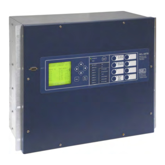
SEL-487B Bus Differential Relay
Busbar and Breaker Failure Protection,
Automation, and Control System
Major Features and Benefits
The SEL-487B Relay provides bus current differential protection, circuit breaker failure protection, and
backup overcurrent protection. The relay has 21 analog current inputs and three analog voltage inputs. For
buses with no more than seven terminals, use one SEL-487B in a single-relay application. For buses with
eight to ten terminals, use two SEL-487B relays. For buses with as many as 21 terminals, use three SEL-487B
relays; each relay provides as many as six independent and adaptable zones of protection. Contact SEL
Research and Development for methods on protecting larger systems.
➤
Busbar differential protection operates in less than one cycle to increase system stability margins and
reduce equipment damage.
➤
Flexible zone selection and six differential zones provide protection for multiple busbar applications.
➤
Failed CT detection elements reliably indicate open and shorted CTs for alarming and/or blocking.
➤
Differential protection accommodates as high as 10:1 CT ratio mismatch without auxiliary CTs.
➤
Differential protection is secure for external faults with minimal CT requirements.
➤
Breaker failure protection for each terminal integrates bus and breaker failure protection.
➤
Instantaneous and inverse time-overcurrent elements provide backup protection for each terminal.
➤
Negative- and zero-sequence over- and undervoltage elements provide for differential element supervi-
sion.
➤
Three dedicated check zones are available in each relay to supervise complex bus differential schemes.
➤
Interconnection with automation systems uses IEC 61850 or DNP3 protocols directly or DNP3
through a Communications Processor. Use FTP for high-speed data collection.
Schweitzer Engineering Laboratories, Inc.
SEL-487B Data Sheet
Advertisement
Table of Contents

Related Manuals for Sel SEL-487B


Summary of Contents for Sel SEL-487B
- Page 1 SEL-487B in a single-relay application. For buses with eight to ten terminals, use two SEL-487B relays. For buses with as many as 21 terminals, use three SEL-487B relays; each relay provides as many as six independent and adaptable zones of protection. Contact SEL Research and Development for methods on protecting larger systems.
-
Page 2: Functional Overview
Axion. The Axion provides remote analog and digital data over an IEC 61158 EtherCAT TiDL net- work. This technology provides very low and deterministic latency over a fiber point-to-point architec- ture. The SEL-487B-1 Relay can receive fiber links from as many as eight Axion remote data acquisition nodes. -
Page 3: Protection Features
Protection Features Order the 9U chassis version of the SEL-487B to equip the use of up to six zones of differential protection, the relay with a maximum of four interface boards. With advanced zone selection algorithms, and per-terminal four interface boards, the relay has a total of 103 inputs breaker failure and overcurrent protection. - Page 4 SOUTH Terminals in Protection Zone 4 SODIUM NEON Bus-Zones in Protection Zone 4 WEST =>> Figure 5 Result of ZONE Command, Showing the Protection Zone Configuration After Zone 1 Merges With Zone 2 SEL-487B Data Sheet Schweitzer Engineering Laboratories, Inc.
-
Page 5: Differential Protection
During an internal fault, the check zone differential element will assert. During an external fault, the check End-Zone Protection zone element will remain deasserted. To illustrate the flexibility of use of SEL control OGIC Differential Protection equations for user-defined conditions, consider the ease of achieving end-zone protection with the SEL-487B. -
Page 6: Voltage Elements
(see Figure 9). Figure 10 relay to the SEL-487B; you can set any terminal to either shows an external fault with heavy CT saturation, internal or external breaker failure protection. -
Page 7: Overcurrent Elements
Intermediate Intermediate Position Position Closed Open Closed Disconnect Switch Starts to Close Disconnect Switch Starts to Open Figure 12 Disconnect Switch Auxiliary Contact Requirements for the Zone Selection Logic; No CT Switching Required Schweitzer Engineering Laboratories, Inc. SEL-487B Data Sheet... - Page 8 Bus 2 operations, and emergency contingencies. Applications Figure 16 shows a station with double bus sections and a bus tie breaker. Use a single SEL-487B for this Figure 14 A Single CT With Two CT Cores Configured in application. Overlap...
- Page 9 2000/5 1000/5 200/5 Bus 1 Figure 17 Two Single SEL-487B Relays Protecting the Two Busbars in a Breaker-and-a-Half Busbar Configuration For stations with 10 to 21 terminals (Figure 18), use independently; the only communication among relays is ITS ® three separate SEL-487B relays and wire analog current communication and IRIG-B.
- Page 10 SEL-487B (A-Phase) Figure 18 Three SEL-487B Relays Protect Two Main Busbars and a Transfer Busbar, Bus Coupler, and 20 Terminals Optimize your SEL-487B by protecting both HV and LV four busbars (two HV and two LV) still leaves two zones busbars with three relays.
- Page 11 TRFR_2 LVCTS HVCTS SEL-487B 4000/5 400/5 LVCTS 3-Phase PT Bus 4 Check Zone LV Bus 3 400/5 400/5 800/5 1600/5 FDR_4 FDR_12 Figure 19 Three SEL-487B Relays Protect Both HV and LV Busbars Schweitzer Engineering Laboratories, Inc. SEL-487B Data Sheet...
-
Page 12: Sntp Time Synchronization
SEL-2725 SEL-487B SEL-487B SEL-487E SEL-487E SEL-487E SEL-487E Figure 20 Time Synchronize SEL-487B Relays With or Without External Clock Source Figure 22 SNTP Diagram Precision Time Protocol (PTP) Automation Time Synchronization Time-Domain Link (TiDL) Technology In addition to IRIG-B, the relay can be time synchro-... - Page 13 OGIC Use remote control points for SCADA-type control Features operations (e.g., trip, settings group selection). Use the SEL-487B control logic to replace the Replace traditional latching relays for such functions as following: remote control enable with 32 latching control points.
-
Page 14: Mirrored Bits Communications
ERATOR Expanded Capabilities and Aliases ® Windows 7 and Windows 8 operating systems, and can be used to open COMTRADE files from SEL and other Expanded SEL control equations (Table 6) put relay OGIC products. You can also use QuickSet to ERATOR logic in the hands of the protection engineer. -
Page 15: Communications Features
Both Relays Through One Connection ➤ Communications Features 10/100BASE-T Twisted Pair Network ➤ 100BASE-FX Fiber-Optic Network The SEL-487B offers the following communications fea- tures: Communicate using IEC 61850 Logical Nodes and ➤ GOOSE Messages, or DNP3 LAN/WAN. Four independent EIA-232 serial ports ➤... -
Page 16: Parallel Redundancy Protocol (Prp)
FTP can also be to remote SCADA client devices. transferred via MMS file services. You can order the SEL-487B with embedded IEC 61850 MMS Authentication protocol operating on 10/100 Mbps Ethernet. EC 61850... -
Page 17: Additional Features
Distributed Network Protocol with point remapping. Includes access to metering data, protection elements, contact I/O, targets, SER, relay summary event reports, and settings groups. SEL protocol for exchanging digital and analog information among SEL relays and for use as IRRORED low-speed terminal connection. -
Page 18: Control Inputs And Outputs
PT ALARM Potential transformer alarm contact status. Set the input debounce time independently Expanded Front-Panel LED Functions for each input or as a group. You can use SEL OGIC Phase Undervoltage control equations to program each control output. Phase Overvoltage... - Page 19 CT ratio and polarity. Differential metering shows the operating and restraint currents, as Each SEL-487B provides event reports for analysis with well as the reference current, for each zone. ® software such as the...
-
Page 20: Sequential Events Recorder (Ser)
Into a Single Window DC Quality Assurance Event Summary The SEL-487B measures and reports the substation bat- Each time the relay generates a standard event report, it tery voltage for one battery system. The relay provides also generates a corresponding Event Summary. This is a... -
Page 21: Front- And Rear-Panel Diagrams
Front- and Rear-Panel Diagrams i3879a Figure 32 Standard Front-Panel Diagram, 9U Chassis Size, Panel-Mount Option, Showing the Front Panel With LCD, Navigation Pushbuttons, 16 Target LEDs, Reset, and Eight Programmable Pushbuttons Schweitzer Engineering Laboratories, Inc. SEL-487B Data Sheet... - Page 22 SEL–487B i4190b Figure 33 Expanded Front-Panel Diagram, 9U Chassis Size, Panel-Mount Option, Showing Extended Front-Panel HMI With LCD, Navigation Pushbuttons, 24 Tricolor LEDs, Reset, and 12 Programmable Pushbuttons SEL-487B Data Sheet Schweitzer Engineering Laboratories, Inc.
- Page 23 Figure 34 Rear-Panel Diagram of the 9U Chassis With Four INT4 Interface Boards Schweitzer Engineering Laboratories, Inc. SEL-487B Data Sheet...
- Page 24 Figure 35 Rear-Panel Diagram of the 7U Chassis With Two INT4 Interface Boards Figure 36 Rear Panel With EtherCAT Board SEL-487B Data Sheet Schweitzer Engineering Laboratories, Inc.
-
Page 25: Relay Dimensions
Relay Dimensions Figure 37 Dimensions for Rack- and Panel-Mount Models Schweitzer Engineering Laboratories, Inc. SEL-487B Data Sheet... -
Page 26: Specifications
6 A continuous carry at 70°C Frequency and Rotation 4 A continuous carry at 85°C 1 s Rating: 50 A System Frequency: 50/60 Hz MOV Protection Phase Rotation: ABC or ACB (maximum voltage): 330 Vdc SEL-487B Data Sheet Schweitzer Engineering Laboratories, Inc. - Page 27 Logic Low Threshold: 50 or > 1 k 110 Vac: Pickup 75.1–132.0 Vac; Input Impedance: Dropout < 46.6 Vac Dielectric Test Voltage: 0.5 kVac 125 Vac: Pickup 89.6–150.0 Vac; Dropout < 53.0 Vac Schweitzer Engineering Laboratories, Inc. SEL-487B Data Sheet...
- Page 28 Class 2 (response) IEC 60255-21-2:1988 Severity Level: Class 1 (shock withstand, bump); Class 2 (shock response) IEC 60255-21-3:1993 Severity Level: Class 2 (quake response) Object Penetration IEC 60529:2001 + CRGD:2003 Protection Class: IP30 SEL-487B Data Sheet Schweitzer Engineering Laboratories, Inc.
-
Page 29: Reporting Functions
±1.50 cycles, ±4% of curve time (for current between 2 and 30 multiples of Differential Elements pickup) Number of Zones: Reset: 1 power cycle or Electromechanical Reset Number of Check Zones: Emulation time Schweitzer Engineering Laboratories, Inc. SEL-487B Data Sheet... -
Page 30: Metering Accuracy
1.5 cycles (all elements but DC1R) Setting Range DC Settings: 1 Vdc Steps (OFF, 15–300 Vdc) AC Ripple Setting: 1 Vac Steps (1–300 Vac) Pickup Accuracy: ±10% ±2 Vdc (DC1RP) ±3% ±2 Vdc (all elements but DC1RP) SEL-487B Data Sheet Schweitzer Engineering Laboratories, Inc. - Page 31 Notes Schweitzer Engineering Laboratories, Inc. SEL-487B Data Sheet...
- Page 32 2350 NE Hopkins Court • Pullman, WA 99163-5603 U.S.A. trademark of their respective holders. No SEL trademarks may be used without written Tel: +1.509.332.1890 • Fax: +1.509.332.7990 permission. SEL products appearing in this document may be covered by U.S. and Foreign selinc.com • info@selinc.com patents.
Need help?
Do you have a question about the SEL-487B and is the answer not in the manual?
Questions and answers