Sign In
Upload
Manuals
Brands
SEL Manuals
Other
SEL-421
SEL SEL-421 Protection Control System Manuals
Manuals and User Guides for SEL SEL-421 Protection Control System. We have
2
SEL SEL-421 Protection Control System manuals available for free PDF download: Instruction Manual, User Manual
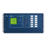
SEL SEL-421 Instruction Manual (705 pages)
Protection and Automation System
Brand:
SEL
| Category:
Other
| Size: 4 MB
Table of Contents
Table of Contents
3
List of Tables
9
Jumpers...................................................................................................................................................... U
9
Features..............................................................................................................................................
11
Array
11
List of Figures
23
Connection............................................................................................................................................
24
Array
24
Manual Overview
33
Applications
34
Conventions
36
Examples
36
Commands
37
Numbers
37
Safety Information
37
Logic Diagrams
38
SEL-421 Cautions, Warnings, and Dangers
39
Protection Functions
43
Current and Voltage Source Selection
44
Current Source Switching
44
Current and Voltage Source Connections for the SEL-421 Relay
44
Applications................................................................................................................................................. U
44
Main and Alternate Line Current Source Assignments
45
Combined Currents for Line Current Source Assignment
45
Breaker Current Source Assignments
45
Available Current Source Selection Settings Combinations
46
Current Source Uses
48
Voltage Source Switching and Uses
48
Available Voltage Source-Selection Setting Combinations
49
Default Applications
50
ESS := 1, Single Circuit Breaker Configuration
50
ESS := 1, Current and Voltage Source Selection
51
ESS := 2, Single Circuit Breaker Configuration
51
Configuration—Independent Current Inputs
52
ESS := 2, Current and Voltage Source Selection
52
ESS := 3, Double Circuit Breaker Configuration
52
Configuration—Common Current Inputs
53
ESS := 3, Current and Voltage Source Selection
53
ESS := 4, Double Circuit Breaker Configuration
53
Tapped Line
54
ESS := 4, Current and Voltage Source Selection
54
Tapped EHV Overhead Transmission Line
54
Single Circuit Breaker with Current Polarizing Source
55
ESS := Y, Tapped Line
55
Using ALTI and ALTV
56
Frequency Estimation
57
Frequency Estimation Outputs
57
Time-Error Calculation
58
Frequency Estimation for Protection Functions
58
Description and Settings
58
Time Error Command
59
Time-Error Calculation Inputs and Outputs
59
Sample TEC Command Response
59
Fault Location
60
Fault Location Triggering Elements
60
Fault Type
61
Fault Location Settings
61
Fault Location Relay Word Bit
61
Open Phase Detection Logic
62
Pole Open Logic
62
Open Phase Detection Relay Word Bits
62
Pole Open Logic Settings
62
EPO Setting Selections
63
Pole Open Logic Relay Word Bits
63
Pole Open Logic Diagram
64
Loss-Of-Potential Logic
65
Setting ELOP := N
65
Setting ELOP := y
66
Setting ELOP := Y1
66
LOP Logic Setting
66
LOP Logic Relay Word Bits
66
LOP Logic
68
Fault Type Identification Selection Logic
69
Ground Directional Element
69
FIDS Relay Word Bits
69
Directional Elements Supervising Ground Elements
69
Settings
70
Ground Directional Element Settings
70
Ground Directional Element Settings AUTO Calculations
70
Detailed Settings Description
71
50FP and 50RP
71
Z2F and Z2R
71
A2 and K2
71
Directional Element Enables
72
A0
72
Order
72
E32Iv
72
Q and 32QG Enable Logic Diagram
73
V and 32I Enable Logic Diagram
73
Ground Directional Element Relay Word Bits
74
Best Choice Ground Directional Logic
75
Negative-Sequence Voltage-Polarized Directional Element Logic
76
Zero-Sequence Voltage-Polarized Directional Element Logic
76
Ground Directional Element Output Logic Diagram
77
Ground Directional Element Equations
78
Phase and Negative-Sequence Directional Elements
80
Directionality
81
P, Phase Directional Element Logic Diagram
81
Q, Negative-Sequence Directional Element Logic Diagram
81
CVT Transient Detection
82
Zone Directional Settings
82
CVT Transient Detection Logic Setting
82
CVT Transient Detection Logic Relay Word Bit
82
Series-Compensation Line Logic
83
CVT Transient Detection Logic
83
Series-Compensation Line Logic Relay Settings
83
Load-Encroachment Logic
84
Load-Encroachment Logic Diagram
84
Load-Encroachment Characteristics
84
Out-Of-Step Logic
85
Load-Encroachment Logic Relay Settings
85
Load-Encroachment Logic Relay Word Bits
85
OOS Characteristics
86
OOS Logic Relay Settings
87
OOS Logic Relay Word Bits
88
OOS Override Logic
89
OOS Positive-Sequence Measurements
89
OOS Logic Diagram
90
Mho Ground Distance Elements
91
Open-Pole OSB Unblock Logic
91
Mho Ground Distance Element Settings
92
Mho Ground Distance Elements Relay Word Bits
92
Zone 1 Mho Ground Distance Element Logic Diagram
93
Zone 2 Mho Ground Distance Element Logic Diagram
94
Zones 3, 4, and 5 Mho Ground Distance Element Logic Diagram
95
Quadrilateral Ground Distance Elements
96
Quadrilateral Ground Distance Element Settings
96
Quadrilateral Ground Distance Elements Relay Word Bits
97
Zone 1 Quadrilateral Ground Distance Element Logic Diagram
97
Zone 2 Quadrilateral Distance Element Logic Diagram
98
Zones 3, 4, and 5 Quadrilateral Ground Distance Element Logic
99
Mho Phase Distance Elements
100
Mho Phase Distance Element Settings
100
Mho Phase Distance Elements Relay Word Bits
100
Zone 1 Mho Phase Distance Element Logic Diagram
101
Zone 2 Mho Phase Distance Element Logic Diagram
102
Zone Time Delay
103
Independent Zone Timing
103
Zones 3, 4, and 5 Mho Phase Distance Element Logic Diagram
103
Common Zone Timing
104
Zone Delay Settings
104
Zone Time Delay Relay Word Bits
104
Zone Timers
105
Instantaneous Line Overcurrent Elements
106
Phase Overcurrent Element Settings
106
Negative-Sequence Overcurrent Element Settings
107
Residual Ground Overcurrent Element Settings
107
Phase Instantaneous/Definite-Time Line Overcurrent Relay Word Bits
108
Phase Instantaneous/Definite-Time Overcurrent Elements
110
Residual Ground Instantaneous/Directional Overcurrent Elements
111
Inverse-Time Overcurrent Elements
112
Selectable Current Quantities
113
Selectable Inverse-Time Overcurrent Settings
113
Time-Current Operating Characteristics
114
Equations Associated with U.S. Curves
115
Equations Associated with IEC Curves
115
Multiples of Pickup
116
Switch-Onto-Fault Logic
126
Selectable Inverse-Time Overcurrent Element Logic Diagram
126
Circuit Breaker Opened SOTF Logic
126
Circuit Breaker Closed SOTF Logic
127
SOTF Options
127
SOTF Settings
127
SOTF Relay Word Bits
127
SOTF Logic Diagram
128
Communications-Assisted Tripping Logic
129
ECOMM Setting
129
Required Zone Directional Settings
129
Directional Comparison Blocking Scheme
130
Coordination Timers
130
Starting Elements
131
Nondirectional Start
131
Directional Start
131
Extension of the Blocking Signal
131
Stopping Elements
132
Three-Terminal Line
132
DCB Settings
132
DCB Relay Word Bits
132
Permissive Overreaching Transfer Tripping Scheme
133
DCB Logic Diagram
133
POTT Scheme
133
Pott
134
Pott2
134
Pott3
134
POTT Scheme Logic
134
Weak-Infeed Logic
135
Echo
135
Three-Terminal Lines
136
Cross-Country Faults
136
POTT Settings
136
POTT Relay Word Bits
137
Permissive Trip Receiver Logic Diagram
138
POTT Logic Diagram
139
POTT Cross-Country Logic Diagram
140
POTT Scheme Logic (ECOMM := POTT3) with Echo and Weak Infeed
141
Directional Comparison Unblocking Scheme Logic
142
DCUB Settings
143
GARD1D: Guard-Present Delay
143
UBDURD: DCUB Disable Delay
144
UBEND: DCUB Duration Delay
144
DCUB Relay Word Bits
144
Permissive Trip Received Logic Diagram
145
DCUB Logic Diagram
146
Trip Logic
147
Three-Pole Tripping
147
Single-Pole Tripping
147
Additional Settings for Single Pole Tripping (SPT)
147
Trip Unlatch Options
148
DTA, DTB, and DTC
148
Trsotf
148
Trcomm
148
Timers
149
Setting TULO Unlatch Trip Options
149
Ultr
149
Minimum Trip Duration
149
Trip Output Signals
150
Manual Trip Logic
150
Trip Logic Settings and Relay Word Bits
150
Trip Logic Relay Word Bits (Sheet 1 of 2)
151
Trip Logic Diagram
154
Circuit Breaker Failure Protection
157
Trip a Unlatch Logic
157
Trip During Open Pole
157
Failure to Interrupt
158
Circuit Breaker Failure Protection Logic
158
Retrip Logic
158
Circuit Breaker Failure Protection Logic: Multiphase Faults
159
Circuit Breaker Failure Protection Logic: Single-Phase Faults
159
Current-Supervised Three-Pole Retrip Logic
160
Scheme 2 Single-Pole Circuit Breaker Failure Protection Logic
160
Circuit Breaker Failure Initiation Dropout and Seal-In
161
Current-Supervised Single-Pole Retrip Logic
161
Load Current Detection: 50LP1
162
Time Delay on Pickup: LCPU1
162
Circuit Breaker Flashover Protection
163
Circuit Breaker Failure Trip Logic
163
Load Current Circuit Breaker Failure Initiation: BFILC1
163
Unlatch Circuit Breaker Failure Trip Equation
163
Circuit Breaker Failure Protection Logic Settings
164
Circuit Breaker Failure Relay Word Bits
164
Circuit Breaker Failure Seal-In Logic Diagram
166
Failure to Interrupt Load Current Logic Diagram
166
Flashover Protection Logic Diagram
167
Circuit Breaker Failure Trip Logic Diagram
167
Auto-Reclosing and Synchronism Check
169
Auto-Reclosing
170
Logical States
170
Start (79STRT)
170
Reset (BK1RS, BK2RS)
170
Single-Pole Auto-Reclose (79CY1)
171
Three-Pole Auto-Reclose (79CY3)
171
Lockout (BK1LO, BK2LO)
171
State Diagram
171
One-Circuit-Breaker Auto-Reclosing
172
One Circuit Breaker Auto-Reclose Modes
172
Single-Pole Mode
173
SPRCD Reclaim Timing
173
Three-Pole Mode
174
Lockout State from 79CY1
174
3PRCD Reclaim Timing
174
Single- and Three-Pole Mode
175
Lockout State from 79CY3
175
Three-Pole Priority
175
Active Circuit Breakers
176
Enable Auto-Reclose Logic for One Circuit Breaker
176
Three-Pole Trip Circuit Breaker
176
Single-Pole Trip Circuit Breaker
176
Recloser Mode Enables
177
Trip Logic and Reclose Sources
177
Internal Recloser
177
One Circuit Breaker Modes of Operation
177
Two-Circuit-Breaker Auto-Reclosing
178
External Recloser
178
SPLSHT Deasserted (Single-Pole Shot Remains)
180
3PLSHT Deasserted (Three-Pole Shot Remains)
182
3PLSHT Asserted (Last Shot)
182
Example One: no Follower
186
Reset State and 79CY3 Cycle State
186
Lockout State
187
Reset State after Reclaim Time
187
Block Reclosing with Enable Settings
187
Example Two: BK2 as Successful Follower and Dynamic Leader
188
Reset State
188
Example Three: BK2 as Conditional Follower
189
79CY3 Cycle State
189
Example Four: Input Selection of Leader
190
Three-Pole Trip Circuit Breakers
191
Two-Circuit-Breaker Three-Pole Reclose Initial Settings
192
Two-Circuit-Breaker Single-Pole Reclose Initial Settings
192
Auto-Reclosing.............................................................................................................................................r
192
Circuit Breaker BK1 Modes of Operation
193
Circuit Breaker BK2 Modes of Operation
193
Trip Logic Enable Options
194
Auto-Reclose Logic Diagrams
195
Circuit Breaker Pole-Open Logic Diagram
195
Line-Open Logic Diagram When E79 := y
196
Line-Open Logic Diagram When E79 := Y1
196
Single-Pole Reclose Enable
197
Three-Pole Reclose Enable
197
One Circuit Breaker Single-Pole Cycle State (79CY1)
198
One Circuit Breaker Three-Pole Cycle State (79CY3)
199
Two Circuit Breakers Single-Pole Cycle State (79CY1) When E79 := y
200
Two Circuit Breakers Single-Pole Cycle State (79CY1) When E79 := Y1
202
Two Circuit Breakers Three-Pole Cycle State (79CY3) When E79 := y
204
Two Circuit Breakers Three-Pole Cycle State (79CY3) When E79 := Y1
207
Manual Closing
209
If a Manual Close Is Successfully Issued for Breaker BK1
209
If Breaker BK1 Closes Successfully
210
If Breaker BK1 Does Not Close Successfully
210
Manual Close Logic
211
Voltage Checks for Auto-Reclosing and Manual Closing
212
Live Line/Live Bus
212
Supervising Auto-Reclosing
213
Supervising Manual Closing
213
Voltage Check Element Applications
213
Voltage Check Element Logic
214
Auto-Reclose Logic Settings
214
Auto-Reclose Logic Relay Word Bits
216
Synchronism Check
218
Generalized System
218
Paralleled and Asynchronous Systems
219
Voltage Angle Difference Estimate
219
Partial Breaker-And-A-Half or Partial Ring-Bus Breaker Arrangement
219
Single-Phase Voltage Inputs
220
Voltage Angle Difference in a Paralleled System
220
Synchronism-Check Voltages for Two Circuit Breakers
220
Synchronism-Check Logic Outputs
221
Synchronism-Check Settings
221
Synchronism-Check Relay Word Bits
222
Supervising Auto-Reclosing of Circuit Breaker BK1
223
PT Connections
223
Manual Closing of Circuit Breaker BK1
223
Voltage Magnitude and Angle Compensation
224
Synchronism-Check Voltage Reference
225
Normalized Synchronism
225
Voltage Checks and Blocking Logic
226
Voltage Magnitude Checks
226
Normalized Synchronism-Check Voltage Sources VS1 and VS2
226
Block Synchronism Check
227
Synchronism-Check Enable Logic
227
Healthy Voltage Window and Indication
227
Angle Difference Settings ANG1BK1 and ANG2BK1
228
Synchronism-Check Element Outputs 25W1BK1 and 25A1BK1
228
“No Slip” Synchronism Check
228
Slip Frequency and SFZBK1
229
Synchronism-Check Element Output Effects
229
Positive Slip Frequency
230
Negative Slip Frequency
231
“No-Slip” Condition
231
Selogic Control Equation Programming
237
Selogic Control Equation History
237
Separation of Protection and Automation Areas
238
Protection and Automation Separation
239
Fixed Selogic Control Equations
240
Assignment Statements
241
Comments
242
Control Equation Setting Structure
242
Protection
243
Control Equation Programming Areas
243
Multiple Setting Groups
244
Automation
244
Outputs
244
Setting Groups: Application Ideas
245
Active Setting Group Indication
245
Active Setting Group Selection
245
Active Setting Group Changes
246
Active Setting: Nonvolatile State
246
Power Loss
246
Settings Change
246
Control Equation Capacity
247
Control Equation Elements
248
Relay Word Bits and Analog Quantities
248
Special Condition Bits
248
Control Equation Variables
249
First Execution Bit Operation on Power-Up
249
First Execution Bit Operation on Automation Settings Change
249
Control Equation Variable Quantities
249
Control Equation Math Variable Quantities
250
Control Equation Math Variables
250
Latch Bits
251
Latch Bit Quantities
251
Latch Bit Parameters
251
Protection Latch Bits
251
EXAMPLE 3.6 Protection Latch Bits
252
Conditioning Timers
253
Automation Latch Bits
253
Conditioning Timer Quantities
253
Conditioning Timer Parameters
253
Conditioning Timer with Pickup and no Dropout Timing Diagram
254
Conditioning Timer with Pickup Not Satisfied Timing Diagram
254
Conditioning Timer with Dropout and no Pickup Timing Diagram
255
Conditioning Timer with Pickup and Dropout Timing Diagram
255
Sequencing Timers
256
EXAMPLE 3.7 Conditioning Timer Programming and Operation
256
Sequencing Timer Quantities
257
Sequencing Timer Parameters
257
Sequencing Timer Timing Diagram
257
Counters
258
Automation Sequencing Timer Programming
258
Counter Quantities
259
Counter Parameters
259
Counter Programming
259
Aliases
260
Assigning and Removing Aliases
260
Control Equation Operators
261
Operator Precedence
261
Boolean Operators
261
Operator Precedence from Highest to Lowest
261
Parentheses
262
Boolean Operator Summary
262
Parentheses Operation in Boolean Equation
262
Not
263
And
263
Or
263
R_Trig
263
F_Trig
264
R_TRIG Timing Diagram
264
F_TRIG Timing Diagram
264
Comparison
265
Math Operators
265
Comparison Operations
265
Math Operator Summary
265
Math Error Detection
266
EXAMPLE 3.13 Using Parentheses in Math Equations
266
Math Error Examples
266
Arithmetic
266
Using Arithmetic Operations
267
Sqrt
267
Using the SQRT Operator
267
LN, EXP, and LOG
268
Using the LN, EXP, and LOG Operators
268
Using the sin and COS Operators
268
ASIN and ACOS
269
Using the ASIN and ACOS Operators
269
Using the ABS Operator
269
Using the CEIL Operator
269
Effective Programming
270
Using the FLOOR Operator
270
Using the Negation Operator
270
Planning and Documentation
270
Testing
271
SEL-311 and SEL-351 Series Users
272
Converting SEL-311
273
Converting SEL-311 Series Relay Latch Bits
274
Communications Interfaces
275
Communications Protocols
275
Serial Communication
276
Eia-232
276
SEL-421 3U Chassis Front-Panel Layout
276
EIA-232 Communications Cables
277
SEL-421 3U Rear-Panel Layout
277
EIA-232 Connector Pin Numbers
277
EIA-232 Pin Assignments
277
Communications Interfaces ..........................................................................................................................R
277
Communications Card
278
Fiber-Optic Interface
278
Eia-485
278
Ethernet Card
278
Network Configuration
279
Ethernet Card Network Configuration Settings
279
DEFRTR Address Setting Examples
280
Network Port Fail-Over Operation
280
Network Address Resolution
281
Data Access Settings
281
IP Network Address Resolution Settings
281
Ftp
281
File Structure
282
Basic File Structure
282
Access Control
283
Telnet
283
Ethernet Card FTP Settings
283
Ethernet Card Commands
284
Ethernet Card Telnet Settings
284
Using Commands
284
Command Summary
285
Control Characters
285
Access Levels
285
Ethernet Card Access Levels
285
2Access
286
Access Level User Names and Passwords
286
Access
287
Date
287
Dnpmap
287
Goose
288
Help
290
ID
290
ID Command Internal Parameters Displayed
290
Memory
291
Ping
291
Quit
291
Status
292
Time
292
Table 4.18 Communications Card Database Regions
293
SEL-421 Communications Card Database Structure
293
Data Region METER Map
300
SEL Communications Protocols
301
Serial Port Hardware Protocol
301
Hardware Handshaking
301
Software Protocol Selections
302
Data Frame
302
Supported Serial Command Sets
302
Protocol Active When Setting PROTO := SEL
303
Virtual Serial Ports
303
SEL ASCII Commands
303
SEL Compressed ASCII Commands
304
Selected ASCII Control Characters
304
Compressed ASCII Message Format
305
Compressed ASCII Commands
305
Interleaved ASCII and Binary Messages
307
Software Flow Control
307
Automatic Messages
308
Timeout
308
Fast Commands and Response Descriptions
309
Fast Operate Command Types
309
Virtual File Interface
311
System Data Format
311
Comma-Delimited Text Rules
311
Root Directory
312
Settings Directory
312
Reports Directory
313
Events Directory
313
Settings Directory Files
313
Ethernet Card Subdirectory
314
EVENTS Directory Files (for Event 10001)
314
CARD Subdirectory
314
SEL Mirrored Bits Communications
315
Mb8
316
Message Transmission
316
Message Reception Overview
317
Message Decoding and Integrity Checks
317
Channel Synchronization
318
Loopback Testing
318
Channel Monitoring
318
Protocol for the Pulsar 9600-BPS Modem
318
SEL Distributed Port Switch Protocol (LMD)
321
Initialization
321
SEL-2885 Initialization String [MODE PREFIX ADDR:SPEED]
322
SEL-2600A RTD Module Operation
323
Operational Overview
323
SEL-2600A RTD Module and the SEL-421
323
RTD Status Bits
323
MET T Command Response
324
MET T Command Response for Status Problem
324
MET T Command Status Messages
324
DNP3 Communications
325
Introduction to DNP3
325
DNP3 Specifications
325
Data Handling
326
Objects
326
DNP3 Implementation Levels
326
Access Methods
327
Function Codes
327
Qualifier Codes and Ranges
327
Selected DNP3 Function Codes
327
Binary Control Operations
328
Conformance Testing
328
Data Link Layer Operation
328
DNP Access Methods
328
DNP3 in the SEL-421
329
Network Medium Contention
329
Data Access
329
DNP Access Methods (Sheet 1 of 2)
329
Collision Avoidance
330
Transmission Control
330
Event Data
330
Binary Controls
331
SEL-421 Event Buffer Capacity
331
Time Synchronization
332
Modem Support
332
DNP3 Settings
332
SEL-421 Port DNP Protocol Settings
333
Configurable Data Mapping
334
SEL-421 DNP Map Settings
334
Warm Start and Cold Start
335
DNP3 Documentation
336
Device Profile
336
SEL-421 DNP3 Device Profile
336
Object List
337
SEL-421 DNP Object List
337
Default Data Map
340
SEL-421 DNP3 Default Data Map
341
SEL-421 Object 1, 2 Relay Word Bit Mapping
345
Object 1, 2 Indices 1600—1615 Front-Panel Targets
347
Reading Relay Event Data
348
Control Point Operation
348
Object 30, 32, Index 176 Upper Byte—Event Cause
348
Object 30, I32, Index 176 Lower Byte—Fault Type
348
SEL-421 Object 12 Trip/Close Pair Operation
349
SEL-421 Object 12 Code Selection Operation
350
Application Example
351
DNP Application Network Diagram
351
DNP3 Application Example Data Map
351
SEL-421 Example DNP Map Settings
354
SEL-421 Port 3 Example Settings
354
Dnp Lan/Wan
356
DNP LAN/WAN in the SEL-421
356
DNP LAN/WAN Access Methods
357
SEL-421 Ethernet Port DNP3 Protocol Settings
359
Custom Data Mapping
362
SEL-421 DNP LAN/WAN Map Settings
362
Binary Inputs
363
Analog Inputs
364
Binary Outputs
364
Analog Outputs
364
DNP Map Command
364
DNP LAN/WAN Documentation
365
SEL-421 DNP LAN/WAN Device Profile
365
SEL-421 DNP3 Object List
366
SEL-421 DNP LAN/WAN Object 12 Control Point Operation
372
DNP LAN/WAN Application Example
373
DNP LAN/WAN Application Example Ethernet Network
373
DNP LAN/WAN Application Example Custom Data Map
374
DNP LAN/WAN Application Example Protocol Settings
374
Application Example Binary Input Map
376
Application Example Binary Output Map
376
Application Example Analog Input Map
376
DNP LAN/WAN Application Example Analog Output Map
377
Synchrophasors
379
Real-Time Control
380
Real-Time Control Application
381
Remote Relay Global Settings
382
Local Relay Global Settings
383
Remote Relay Port Settings
383
Local Relay Port Settings
383
Synchrophasor Measurement
384
Example COM RTC Command Response
384
High Accuracy Clock Controls Reference Signal (60 Hz System)
384
Waveform at Relay Terminals May Have a Phase Shift
385
Correction of Measured Phase Angle
385
Settings for Synchrophasors
387
Accuracy
387
PMU Settings in the SEL-421 for C37.118 Protocol in Global Setting
388
Time and Date Management
389
SEL-421 Serial Port Settings for Synchrophasors
389
SEL-421 Ethernet Port Settings for Synchrophasors
390
Descriptions of Synchrophasor Settings
390
Mfrmt
390
Mrate
390
Phcomp
391
PMSTN and PMID
391
PHDATAV and VCOMP
391
PHDATAI, PHCURR, IWCOMP, and IXCOMP
391
Synchrophasor Order in Data Stream (Voltages and Currents)
392
Phnr
393
Phfmt
393
Fnr
393
Numana
394
Numdsw
394
User-Defined Analog Values Selected by the NUMANA Setting
394
TREA1, TREA2, TREA3, TREA4, and PMTRIG
395
User-Defined Digital Status Words Selected by the NUMDSW Setting
395
PM Trigger Reason Bits—Ieee C37.118 Assignments
395
Mrtcdly
396
Rtcrate
396
Pmumode
396
Rtcid
396
Synchrophasor Relay Word Bits
397
Synchrophasor Trigger Relay Word Bits
397
Time Synchronization Relay Word Bits
397
Synchrophasor Client Status Bits
397
Synchrophasor Analog Quantities
398
Remote Synchrophasor Data Bits
398
Synchrophasor Aligned Analog Quantities
400
View Synchrophasors by Using the MET PM Command
402
C37.118 Synchrophasor Protocol
403
Sample MET PM Command Response
403
Settings Affect Message Contents
404
Communications Bandwidth
404
Size of a C37.118 Synchrophasor Message
404
Serial Port Bandwidth for Synchrophasors (in Bytes)
405
Protocol Operation
405
Transmit Mode Control
405
PMU Setting Example
406
Independent Ports
406
Determining Settings
407
Example Synchrophasor Global Settings
407
Example Synchrophasor Protection Free-Form Logic Settings
408
Example Synchrophasor Port Settings
408
SEL Fast Message Synchrophasor Protocol
409
SEL-421 Fast Message Synchrophasorsettings
410
Descriptions of Fast Message Synchrophasor Settings
411
Pmid
411
PHDATAV, PHDATAI, and PHCURR
411
Other Settings Not Present
412
Upgrading Previous SEL-421 Synchrophasor Settings
412
Size of an SEL Fast Message Synchrophasor Message
413
Synchrophasor Protocols and SEL Fast Operate Commands
415
IEC 61850 Communications
417
Introduction to IEC 61850
418
IEC 61850 Document Set
418
IEC 61850 Operation
419
Ethernet Networking
419
Object Models
419
Data Mapping
420
Mms
420
Example IEC 61850 Descriptor Components
420
SEL-421 Logical Devices
420
File Services
421
SCL Files
421
Reports
421
SEL-421 Predefined Reports
422
Buffered Report Control Block Client Access
422
Unbuffered Report Control Block Client Access
423
Datasets
424
SEL-421 Datasets
424
Time Stamps and Quality
425
GOOSE Quality
425
GOOSE Processing
426
GOOSE Performance
427
IEC 61850 Configuration
428
IEC 61850 Settings
428
SEL ICD File Versions
428
CID File Conversion
429
ICD Logical Nodes Summary
430
Logical Nodes
432
Logical Device: PRO (Protection)
432
Logical Device: MET (Metering)
436
Logical Device: con (Remote Control)
437
Logical Device: ANN (Annunciation)
438
Protocol Implementation Conformance Statement: SEL-400 Series Devices
447
PICS for A-Profile Support
447
PICS for T-Profile Support
447
MMS Conformance
447
MMS Parameter CBB
450
Alternateaccessselection Conformance Statement
450
Variableaccessspecification Conformance Statement
450
Variablespecification Conformance Statement
451
Read Conformance Statement
451
Getvariableaccessattributes Conformance Statement
451
Definenamedvariablelist Conformance Statement
451
Getnamedvariablelistattributes Conformance Statement
452
Deletenamedvariablelist Conformance Statement
452
GOOSE Conformance
452
ACSI Conformance Statements
453
ACSI Basic Conformance Statement
453
ACSI Models Conformance Statement
453
ACSI Services Conformance Statement
454
ASCII Command Reference
459
Description of Commands
460
Aaccess
460
Bname
460
Breaker
460
BRE N
461
BRE N C and BRE N R
461
BRE C a and BRE R a
461
BRE N H
461
Cal
462
Cascii
462
Cbreaker
462
Cbr
462
Cevent
463
Cbr Terse
463
Cev
463
Cev Ack
463
Advertisement
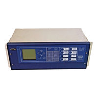
Sel SEL-421 User Manual (318 pages)
Protection,Automation, Control
Brand:
Sel
| Category:
Relays
| Size: 9 MB
Table of Contents
Table of Contents
3
List of Tables
9
Jumpers...................................................................................................................................................... U
9
Features........................................................................................................................................................ U
11
Index
14
Section 4: Basic Relay Operations
22
Connection................................................................................................................................................. U
22
Section 2: Installation
31
List of Equations
31
Section 3: PC Software
31
List of Examples
35
Manual Change Information
37
Preface
39
User's Guide
40
Glossary
40
Section 1: Introduction and Specifications
47
Features
48
Models and Options
51
Applications
52
Section 4: Basic Relay Operations
132
Section 1: Introduction and Specifications
55
Table 1.1 Application Highlights
55
Specifications
57
Section 2: Installation
61
Shared Configuration Attributes
62
Plug-In Boards
72
Table 2.1 I/O Interface Boards Control Inputs
72
Table 2.2 I/O Interface Boards Control Outputs
73
Jumpers
77
Table 2.3 Main Board Jumpers
79
Table 2.4 Main Board Jumpers-JMP1, JMP2, and JMP3
80
Table 2.5 I/O Board Jumpers
85
Front-Panel Labels
86
Table 2.6 Configurable Front-Panel Label Kits
87
Table 2.7 Options for Configurable Front-Panel Labels
88
Relay Placement
91
Connection
93
Table 2.8 Fuse Requirements for the SEL-421 Relay Power Supply
98
AC/DC Connection Diagrams
107
Section 3: PC Software
111
Installing the Computer Software
112
Communications Setup
114
Settings Database Management and Drivers
116
Figure 3.9 HMI Driver Version Number in the HMI Window
118
Create and Manage Relay Settings
119
Figure 3.14 AC SEL ERATOR Software Relay Editor
121
Figure 3.15 Retrieving the Relay Part Number
122
Expression Builder
123
Figure 3.17 Location of EB Option Button
123
Figure 3.18 the AC SEL ERATOR Expression Builder
123
Analyze Events
125
Figure 3.19 Retrieving Relay Event History
125
Figure 3.20 AC SEL ERATOR Event Waveform Window
126
Figure 3.21 Sample Event Oscillogram
126
Figure 3.22 Retrieving Event Report Waveforms
126
Figure 3.23 Sample Phasors Event Waveform Screen
127
Figure 3.24 Sample Harmonic Analysis Event Waveform Screen
127
Figure 3.25 Sample Event Report Summary Screen
128
Figure 3.26 Sample Event Waveform Settings Screen
128
Figure 3.27 AC SEL ERATOR HMI Features
129
HMI Meter and Control
129
Section 4: Basic Relay Operations
131
Figure 4.1 SEL-421 Relay Serial Number Label
132
Inspecting a New Relay
132
Connecting and Applying Power
134
Figure 4.2 Power Connection Area of the Rear Panel
134
Table 4.1 Power Supply Voltage Inputs
134
Establishing Communication
135
Figure 4.3 PORT F, LCD Display, and Navigation Pushbuttons
135
Figure 4.4 Report Header
136
Table 4.2 General Serial Port Settings
136
Changing the Default Passwords
138
Figure 4.5 Access Level Structure
138
Table 4.3 SEL-421 Relay Access Levels
138
Table 4.4 Access Level Commands and Passwords
139
Figure 4.6 Default Passwords
141
Checking Relay Status
142
Figure 4.10 Checking Relay Status: Front-Panel LCD
144
Making Simple Settings Changes
145
Figure 4.11 Relay Settings Structure Overview
146
Table 4.5 Settings Classes and Instances
147
Figure 4.12 Components of SET Commands
148
Table 4.6 Actions at Settings Prompts
149
Figure 4.13 Initial Global Settings
150
Table 4.7 Actions at Text-Edit Mode Prompts
151
Figure 4.14 Using Text-Edit Mode Line Editing to Set Display Points
153
Figure 4.15 Using Text-Edit Mode Line Editing to Delete a Display Point
154
Figure 4.16 Selecting Global Settings in the AC SEL ERATOR Software
156
Figure 4.17 the AC SEL ERATOR Software Global Settings Window
156
Figure 4.18 Uploading Global Settings to the SEL-421 Relay
157
Figure 4.19 DATE and TIME Settings: Front-Panel LCD
158
Figure 4.20 SETTINGS Menus
160
Examining Metering Quantities
161
Figure 4.21 Setting ESS: Terminal
161
Figure 4.22 Setting CTRW and PTRY: Terminal
162
Figure 4.23 Test Connections Using Three Voltage Sources/Three Current Sources
162
Figure 4.24 Test Connections Using Two
163
Figure 4.25 Terminal Screen MET Metering Quantities
164
Figure 4.30 Front-Panel Screens for METER
168
Figure 4.7 Relay Status
168
Reading Oscillograms, Event Reports, and SER
169
Figure 4.34 Relay Event History Dialog Box
172
Figure 4.35 Sample HIS Command Output: Terminal
172
Figure 4.36 EVENTS Folder Files
173
Figure 4.42 Uploading Report Settings to the SEL-421 Relay
178
Figure 4.43 Retrieving SER Records with the AC SEL ERATOR Software
179
Figure 4.44 SER Records in the AC SEL ERATOR HMI
179
Figure 4.45 Setting an SER Element: Terminal
180
Figure 4.46 Reports File Structure
181
Figure 4.47 Terminal Display for PULSE Command
182
Operating the Relay Inputs and Outputs
182
Figure 4.48 Front-Panel Menus for Pulsing OUT104
183
Figure 4.49 Password Entry Screen
184
Figure 4.51 Setting Control Output OUT105: Terminal
186
Figure 4.54 Uploading Output Settings to the SEL-421 Relay
189
Figure 4.55 Setting 52AA1: Terminal
191
Configuring High-Accuracy Timekeeping
196
Table 4.8 Time Source Automatic Switching Enable Settings
196
Figure 4.61 TIME BNC Jacks
197
Figure 4.62 Confirming the High-Accuracy Timekeeping Enable Settings
198
Figure 4.63 Results of the TIME Q Command
198
Table 4.9 Date/Time Last Update Sources
199
Readying the Relay for Field Application
202
Table 4.10 Communications Port Commands that Clear Relay Buffers
203
Section 5: Front-Panel Operations
206
Section 4: Basic Relay Operations
134
Section 5: Front-Panel Operations
205
Figure 5.1 SEL-421 Relay Front Panel
206
Front-Panel Layout
206
Figure 5.2 LCD Display and Navigation Pushbuttons
207
Table 5.1 Front-Panel Inactivity Time-Out Setting
207
Figure 5.3 RELAY ELEMENTS Highlighted in MAIN MENU
208
Table 5.2 Metering Screens Enable Settings
208
Figure 5.4 Sample ROTATING DISPLAY
209
Figure 5.5 Sample Display Points Screen
210
Table 5.3 Display Point Settings
211
Figure 5.6 Fast Meter Display Points Sample Screen
212
Figure 5.7 Contrast Adjustment
213
Front-Panel Menus and Screens
213
Figure 5.8 Enter Password Screen
214
Figure 5.9 Invalid Password Screen
214
Figure 5.10 MAIN MENU
215
Figure 5.12 METER SUBMENU
216
Figure 5.17 RELAY ELEMENTS Screen
220
Figure 5.18 ELEMENT SEARCH Screen
220
Figure 5.19 LOCAL CONTROL Initial Menu
221
Figure 5.21 LOCAL CONTROL Example Menus
223
Table 5.4 Local Bit Control Settings
223
Figure 5.22 OUTPUT TESTING Screen
225
Table 5.5 Settings Available from the Front Panel
225
Figure 5.25 Changing the ACTIVE GROUP
227
Figure 5.26 DATE/TIME Screen
228
Figure 5.31 RESET ACCESS LEVEL Screen
231
Figure 5.33 Sample Status Warning in the LCD Message Area
232
Front-Panel Automatic Messages
232
Figure 5.34 Factory Default Front-Panel Target Areas
234
Operation and Target Leds
234
Table 5.6 TIME Target LED Trigger Elements-Factory Defaults
236
Figure 5.35 Operator Control Pushbuttons and Leds
238
Front-Panel Operator Control Pushbuttons
238
Table 5.7 Operator Control Pushbuttons and Leds-Factory Defaults
238
Figure 5.36 Factory Default Operator Control Pushbuttons-Left Side
239
Figure 5.37 Factory Default Operator Control Pushbuttons-Right Side
240
Section 6: Testing and Troubleshooting
247
Section 5: Front-Panel Operations
207
Section 6: Testing and Troubleshooting Testing Philosophy
242
Table 6.3 Maintenance Testing
243
Testing Features and Tools
245
Figure 6.1 Low-Level Test Interface
247
Table 6.4 UUT Database Entries for SEL-5401 Relay Test System Software-5 a Relay
248
Table 6.5 UUT Database Entries for SEL-5401 Relay Test System Software-1 a Relay
248
Relay Test Connections
249
Figure 6.3 Test Connections Using Two Current Sources for
250
Table 6.6 Phase Instantaneous Overcurrent Pickup
254
Test Methods
254
Figure 6.7 Sample Targets Display on a Serial Terminal
255
Figure 6.8 Viewing Relay Word Bits from the Front-Panel LCD
256
Figure 6.10 Uploading Front-Panel Settings to the SEL-421 Relay
258
Figure 6.12 Uploading Output Settings to the SEL-421 Relay
259
Table 6.7 Selectable Operating Quantity Time-Overcurrent Element (51S1) Default Settings
260
Figure 6.15 Uploading Group 1 and Report Settings to SEL-421 Relay
262
Figure 6.16 HMI Tree View: AC SEL ERATOR Software
263
Figure 6.17 SER Report: AC SEL ERATOR HMI
263
Checking Relay Operation
264
Figure 6.19 Negative-Sequence Instantaneous
266
Figure 6.20 Uploading Group 1 Settings to the SEL-421 Relay
266
Figure 6.21 ELEMENT SEARCH Screen
267
Figure 6.22 RELAY ELEMENTS Screen Containing Element 50Q1
267
Figure 6.27 Uploading Group 1 and
271
Table 6.8 Negative-Sequence Directional Element Settings AUTO Calculations
271
Figure 6.28 RELAY ELEMENTS LCD
272
Figure 6.29 Finding Phase-To-Phase Test Quantities
274
Figure 6.30 Phase Distance Elements Settings: AC SEL ERATOR Software
276
Figure 6.31 RELAY ELEMENTS LCD Screen Containing Element MBC2
276
Relay Self-Tests
277
Figure 6.33 Relay Status from a STATUS a Command on a Terminal
278
Figure 6.34 Compressed ASCII CST Command on a Terminal
279
Relay Troubleshooting
280
Table 6.9 Troubleshooting Procedures
280
Factory Assistance
283
Appendix A: Firmware Versions
285
Table A.1 Firmware Versions
285
Section 6: Testing and Troubleshooting
308
Table 6.2 Commissioning Testing
308
Advertisement
Related Products
SEL SEL-751A
Sel SEL-421-1
Sel SEL-421-5
Sel SEL-421-4
SEL SEL-451-5
Sel SEL-487E-5
Sel SEL-411L
Sel SEL-487E-3
Sel SEL-451-6
Sel SEL-487E-4
SEL Categories
Relays
Controller
Control Systems
Control Unit
Monitor
More SEL Manuals
Login
Sign In
OR
Sign in with Facebook
Sign in with Google
Upload manual
Upload from disk
Upload from URL