
Related Manuals for Sel SEL-421-4


Summary of Contents for Sel SEL-421-4
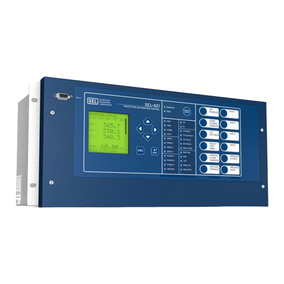
- Page 1 SEL-421-4, -5 Relay Protection and Automation System Instruction Manual User’s Guide 20150504 *PM421-04-NB*...
- Page 2 © 2010–2015 by Schweitzer Engineering Laboratories, Inc. All rights reserved. All brand or product names appearing in this document are the trademark or registered trademark of their respective holders. No SEL trademarks may be used without written permission. SEL products appearing in this document may be covered by U.S. and Foreign patents.
-
Page 3: Table Of Contents
..............................xxi Preface ................................xxxiii User’s Guide Section 1: Introduction and Specifications Features................................ U.1.2 Models and Options............................. U.1.5 SEL-421 Versions and Supported Features ....................U.1.7 Applications..............................U.1.8 Specifications ............................U.1.13 Section 2: Installation Shared Configuration Attributes........................U.2.1 Plug-In Boards............................U.2.11 Jumpers..............................U.2.17 Relay Placement ............................ - Page 4 Section 4: Time-Synchronized Measurements Relay Configuration for High-Accuracy Timekeeping ................A.4.1 Fault Analysis .............................. A.4.6 Power Flow Analysis........................... A.4.7 State Estimation Verification ........................A.4.9 Section 5: Bay Control Overview ..............................A.5.1 Circuit Breaker Status Logic ........................A.5.2 SEL-421-4, -5 Relay Date Code 20150504...
- Page 5 230 kV Tapped Transmission Line Application Example................A.6.1 Section 7: SEL Communications Processor Applications SEL Communications Processors........................ A.7.1 SEL Communications Processor and Relay Architecture ................A.7.3 SEL Communications Processor Example....................A.7.5 Section 8: Direct Network Communication Direct Network Communication ......................... A.8.1 Serial Networking............................
- Page 6 Cybersecurity Features ..........................R.5.25 Section 6: DNP3 Communications Introduction to DNP3 ...........................R.6.1 DNP3 in the SEL-421...........................R.6.7 DNP3 Documentation ..........................R.6.15 SEL-421-0, -1, -2, -3 to SEL-421-4, -5 Mapping..................R.6.42 DNP Serial Application Example.......................R.6.52 DNP3 LAN/WAN Application Example....................R.6.56 Section 7: Synchrophasors Overview ..............................R.7.1 Introduction ..............................R.7.1 Configuring PMU for C37.118 Synchrophasors ..................R.7.2...
- Page 7 Introduction to IEC 61850..........................R.8.2 IEC 61850 Operation............................R.8.3 IEC 61850 Configuration ...........................R.8.12 Logical Nodes.............................R.8.16 Changes from SEL-421-0, -1, -2, -3 to SEL-421-4, -5................R.8.35 Protocol Implementation Conformance Statement: SEL-400 Series Devices ...........R.8.36 ACSI Conformance Statements........................R.8.43 Cybersecurity Features ..........................R.8.47 Section 9: ASCII Command Reference Description of Commands..........................R.9.1...
- Page 8 This page intentionally left blank...
-
Page 9: List Of Tables
Commissioning Testing...................... U.6.2 Table 6.3 Maintenance Testing ......................U.6.3 Table 6.4 UUT Database Entries for SEL-5401 Relay Test System Software—5 A Relay ....U.6.7 Table 6.5 UUT Database Entries for SEL-5401 Relay Test System Software—1 A Relay ....U.6.8 Table 6.6 Phase Instantaneous Overcurrent Pickup ................. - Page 10 List of Tables Table A.2 Revision History ....................U.A.5 BOOT Table A.3 SEL-421-5 ICD File Revision History................U.A.6 Table A.4 Instruction Manual Revision History ................U.A.7 Table B.1 Firmware Upgrade Files.....................U.B.2 Applications Handbook Table 1.1 System Data—230 kV Overhead Transmission Line ............A.1.2 Table 1.2...
- Page 11 SEL Communications Processor Data Collection Automessages........A.7.6 Table 7.4 Fast Message Read Message Settings ................A.7.6 Table 7.5 SEL Communications Processor Port 1 Automatic Messaging Settings ......A.7.7 Table 7.6 SEL Communications Processor Port 1 Region Map ............A.7.7 Table 7.7 SEL Communications Processor METER Region Map ............
- Page 12 Zone Delay Settings ......................R.1.89 Table 1.58 Zone Time Delay Relay Word Bits ...................R.1.89 Table 1.59 Phase Overcurrent Element Settings .................R.1.91 Table 1.60 Negative-Sequence Overcurrent Element Settings............R.1.92 Table 1.61 Residual Ground Overcurrent Element Settings ...............R.1.92 SEL-421-4, -5 Relay Date Code 20150504...
- Page 13 Control Equation Programming Summary ..........R.3.2 OGIC Table 3.3 Definitions for Active Setting Group Indication Relay Word Bits SG1 Through SG6 ..R.3.9 Table 3.4 Definitions for Active Setting Group Switching SEL Control Equation OGIC Settings SS1 Through SS6 ....................R.3.9 Table 3.5 Summary of SEL Control Equation Elements ............R.3.12...
- Page 14 Table 3.25 Comparison Operations.....................R.3.30 Table 3.26 Math Operator Summary....................R.3.30 Table 3.27 Math Error Examples ......................R.3.31 Table 3.28 SEL-311 Series Relays and SEL-421 SEL Control Equation Programming OGIC Features ..........................R.3.36 Table 3.29 SEL-311 Series Relays and SEL-421 SEL Control Equation Boolean Operators..R.3.37 OGIC Table 4.1...
- Page 15 Communications Message Transmission Period........R.5.17 IRRORED Table 5.13 Communications ID Settings for Three-Terminal Application....R.5.17 IRRORED Table 5.14 SEL-2885 Initialization String [MODE PREFIX ADDR:SPEED] ........R.5.18 Table 5.15 RTD Status Bits.........................R.5.19 Table 5.16 MET T Command Status Messages ..................R.5.20 Table 5.17 Settings Associated With SNTP..................R.5.21 Table 5.18...
- Page 16 List of Tables Table 8.3 SEL-421 Logical Devices ....................R.8.4 Table 8.4 Buffered Report Control Block Client Access ..............R.8.8 Table 8.5 Unbuffered Report Control Block Client Access..............R.8.8 Table 8.6 IEC 61850 Settings......................R.8.12 Table 8.7 Logical Device: PRO (Protection)..................R.8.16 Table 8.8 Logical Device: MET (Metering)..................R.8.22 Table 8.9...
- Page 17 MAP 1 Region Command ....................R.9.32 Table 9.82 MET Command.........................R.9.32 Table 9.83 MET AMV Command ......................R.9.33 Table 9.84 MET ANA Command .......................R.9.33 Table 9.85 MET BAT Command ......................R.9.33 Table 9.86 MET D Command......................R.9.34 Table 9.87 MET E Command ......................R.9.34 Date Code 20150504 SEL-421-4, -5 Relay...
- Page 18 STA A Command ......................R.9.54 Table 9.141 STA C and STA R Command....................R.9.54 Table 9.142 STA S Command.......................R.9.54 Table 9.143 STA SC and STA SR Command ..................R.9.54 Table 9.144 SUM Command.........................R.9.55 Table 9.145 SUM ACK Command .......................R.9.55 SEL-421-4, -5 Relay Date Code 20150504...
- Page 19 Table 10.31 Group Settings Categories....................R.10.14 Table 10.32 Line Configuration ......................R.10.15 Table 10.33 Relay Configuration ......................R.10.15 Table 10.34 Mho Phase Distance Element Reach................R.10.16 Table 10.35 Quadrilateral Phase Distance Element Reach ..............R.10.17 Table 10.36 Series Compensation .......................R.10.17 Date Code 20150504 SEL-421-4, -5 Relay...
- Page 20 Table 10.88 Local Control........................R.10.44 Table 10.89 Local Bit SEL ......................R.10.44 OGIC Table 10.90 Report Settings Categories ....................R.10.44 Table 10.91 SER Chatter Criteria......................R.10.45 Table 10.92 SER Points........................R.10.45 Table 10.93 Signal Profile........................R.10.45 Table 10.94 Event Reporting.......................R.10.45 SEL-421-4, -5 Relay Date Code 20150504...
- Page 21 Relay Word Bits: Settings Group Bits................R.A.52 Table A.26 Relay Word Bits: Future Breaker Failure Bits ..............R.A.52 Table A.27 Relay Word Bits: Input Elements..................R.A.52 Table A.28 Relay Word Bits: Protection SEL Variables .............R.A.52 OGIC Table A.29 Relay Word Bits: Protection SEL Latches ...............R.A.53 OGIC Conditioning Timers...........R.A.53...
- Page 22 Relay Word Bits: High-Speed Mho and Quad Ground Distance........R.A.62 Table A.55 Relay Word Bits: High-Speed Mho and Quad Phase Distance........R.A.63 Table A.56 Relay Word Bits: DNP Event Lock..................R.A.64 Table A.57 Relay Word Bits: Synchrophasor SEL Equations/RTC Synchrophasors OGIC Status Bits ........................R.A.64 Table A.58 Relay Word Bits: IRIG-B Control..................R.A.65 Table A.59...
- Page 23 Figure 2.20 Major Component Locations on the SEL-421 Main Board ..........U.2.19 Figure 2.21 Major Component Locations on the SEL-421 INT1, INT2, INT4, INT5, INT6, INT7, and INT8 I/O Boards........................U.2.22 Figure 2.22 Major Component Locations on the SEL-421 INT3 I/O Board........U.2.23 Figure 2.23...
- Page 24 Typical External AC/DC Connections—Single Circuit Breaker ........U.2.46 Figure 2.44 Typical External AC/DC Connections—Dual Circuit Breaker........U.2.47 Figure 2.45 SEL-421 Example Wiring Diagram Using the Auxiliary TRIP/CLOSE Pushbuttons ..U.2.48 Figure 3.1 Terminal Prompt......................... U.3.5 Figure 3.2 QuickSet Driver Information in the FID String ........U.3.5 ERATOR Figure 3.3...
- Page 25 Figure 4.62 Setting BK1TYP in QuickSet ..............U.4.72 ERATOR Figure 4.63 Uploading Global and Breaker Monitor Settings to the SEL-421 ........U.4.73 Figure 4.64 TIME BNC Connector ..................... U.4.75 Figure 4.65 Confirming the High-Accuracy Timekeeping Relay Word Bits ........U.4.75 Figure 4.66...
- Page 26 Figure 6.25 Directional Settings: QuickSet..............U.6.34 ERATOR Figure 6.26 Uploading Group 1 and Breaker Monitor Settings to the SEL-421......... U.6.35 Figure 6.27 RELAY ELEMENTS LCD Screen Containing Elements F32Q and R32Q ....U.6.35 Figure 6.28 Finding Phase-to-Phase Test Quantities ................U.6.37 Figure 6.29...
- Page 27 Fault Current Distribution Through Faulted Line at Station S........A.1.153 Figure 1.47 Timing Diagram for Setting BFPU1—Scheme 2............A.1.154 Figure 1.48 Timing Sequences for Circuit Breaker Failure Protection Scheme 2......A.1.155 Figure 1.49 Circuit Breaker BK1 DC Connections (Two Trip Coils) ..........A.1.158 Date Code 20150504 SEL-421-4, -5 Relay...
- Page 28 SEL-421 Intelligent Circuit Breaker Monitor ..............A.2.2 Figure 2.2 Circuit Breaker Maintenance Curve (Manufacturer’s Data) ..........A.2.4 Figure 2.3 Circuit Breaker Contact Wear Curve With SEL-421 Settings ........... A.2.5 Figure 2.4 Trip Bus Sensing With Relay Input IN106 ................ A.2.8 Figure 2.5 Mechanical Operating Time for Circuit Breaker 1 A-Phase ..........
- Page 29 SEL Communications Processor Star Integration Network ..........A.7.1 Figure 7.2 Multitiered SEL Communications Processor Architecture..........A.7.2 Figure 7.3 Enhancing Multidrop Networks With the SEL Communications Processors....A.7.4 Figure 7.4 Example SEL Relay and SEL Communications Processors Configuration....... A.7.5 Figure 8.1 DNP3 Multidrop Network Topology .................
- Page 30 Figure 8.11 Example Telnet Session ....................A.8.13 Reference Manual Figure 1.1 Current and Voltage Source Connections for the SEL-421 Relay ........R.1.2 Figure 1.2 Main and Alternate Line Current Source Assignments ............R.1.3 Figure 1.3 Combined Currents for Line Current Source Assignment ..........R.1.3 Figure 1.4...
- Page 31 Figure 1.108 Current-Supervised Single-Pole Retrip Logic..............R.1.148 Figure 1.109 No Current/Residual Current Circuit Breaker Failure Protection Logic Diagram..R.1.148 Figure 1.110 Circuit Breaker Failure Seal-In Logic Diagram ..............R.1.153 Figure 1.111 Failure to Interrupt Load Current Logic Diagram............R.1.153 Date Code 20150504 SEL-421-4, -5 Relay...
- Page 32 Synchronism-Check Voltages for Two Circuit Breakers...........R.2.50 Figure 2.21 Synchronism-Check Settings ....................R.2.51 Figure 2.22 Synchronism-Check Relay Word Bits................R.2.51 Figure 2.23 Example Synchronism-Check Voltage Connections to the SEL-421 .......R.2.53 Figure 2.24 Synchronism-Check Voltage Reference................R.2.54 Figure 2.25 Normalized Synchronism-Check Voltage Sources VS1 and VS2........R.2.55 Figure 2.26 Healthy Voltage Window and Indication................R.2.56...
- Page 33 Sample Custom DNP3 Analog Input Map Settings ............R.6.42 Figure 6.6 DNP3 Application Network Diagram ................R.6.52 Figure 6.7 SEL-421 Example DNP Map Settings ................R.6.54 Figure 6.8 DNP3 LAN/WAN Application Example Ethernet Network..........R.6.56 Figure 6.9 Add Binary Inputs to SER Point List ................R.6.57 Figure 7.1...
- Page 34 This page intentionally left blank...
-
Page 35: Preface
Preface This manual provides information and instructions for installing and operating the SEL-421 Relay. The three volumes that comprise this manual are for use by power engineers and others experienced in protective relaying applications. Included are detailed technical descriptions of the relay and application examples. - Page 36 Section 6: Testing and Troubleshooting. Describes techniques for testing, troubleshooting, and maintaining the SEL-421; includes the list of status notification messages and a troubleshooting chart. Appendix A: Firmware and Manual Versions.
- Page 37 Manual Overview Section 7: SEL Communications Processor Applications. Provides examples of how to use the SEL-421 with the SEL-2032, SEL-2030, and SEL-2020 Communications Processors for total substation automation solutions. Section 8: Direct Network Communication. Explains how to use DNP3 (serial and LAN/WAN) and other Ethernet protocols such as Telnet, FTP, and IEC 61850.
- Page 38 Preface Manual Overview CD-ROM The CD-ROM contains the SEL-421 Relay Manual in an electronic form that you can search easily. Safety Information Dangers, Warnings, This manual uses three kinds of hazard statements, defined as follows: and Cautions DANGER Indicates an imminently hazardous situation that, if not avoided, will result in death or serious injury.
- Page 39 Incorporated components, such as LEDs and transceivers are not user Les composants internes tels que les leds (diodes serviceable. Return units to SEL for repair or replacement. électroluminescentes) et émetteurs-récepteurs ne peuvent pas être entretenus par l'usager. Retourner les unités à SEL pour réparation ou remplacement. WARNING AVERTISSEMENT Before working on a CT circuit, first apply a short to the secondary Avant de travailler sur un circuit TC, placez d’abord un court-circuit sur...
- Page 40 Severe power and ground problems can occur on the communications Des problèmes graves d’alimentation et de terre peuvent survenir sur ports of this equipment as a result of using non-SEL cables. Never use les ports de communication de cet appareil si des câbles d’origine standard null-modem cables with this equipment.
- Page 41 R stands for Reference Manual. control SEL trademarks and registered trademarks contain the appropri- OGIC equations ate symbol on first reference in a section. In the SEL-421 Instruc- tion Manual, certain SEL trademarks appear in small caps. These include SEL control equations, M communi-...
- Page 42 SEL-421. Notes Margin notes serve two purposes in the SEL-421 Relay Manual. Notes present valuable or important points about relay features or functions. Use these notes as tips to easier and more efficient operation of the relay. Also in this manual, notes specify differences between the SEL-421-4 and SEL-421-5 models when these differences affect relay functions or operations.
- Page 43 B asserts at the falling edge of input A. New Hardware Built on new hardware that incorporates the new E4 Ethernet card, the SEL-421-4, -5 relays offer the following protection functions in addition to the proven protection elements of the SEL-421-2, -3 relays. SEL-421-4: ➤...
- Page 44 CCOUT01–CCOUT32 Removed—use any visible Relay Word bit In the SEL-421-4, -5, the LED alias settings (TnLEDA) are no longer supported. Their equivalent functionality is available by aliasing the Tn_LED_n bits using SET T. The only difference is that the TnLEDA alias settings accept eight character aliases, whereas aliases set using the SET T command only accept seven characters.
- Page 45 The number of disconnects and breakers that can be controlled by the SEL-421 are a function of the selected mimic display screen. A maximum of ten disconnects and two breakers can be supported in a single mimic display.
-
Page 46: Section 1: Introduction And Specifications Features
U.1.2 Introduction and Specifications Features This section introduces the SEL-421 and provides information on the following topics: ➤ Features on page U.1.2 ➤ Models and Options on page U.1.5 ➤ Applications on page U.1.8 ➤ Specifications on page 1.13 Features The SEL-421 contains many protection, automation, and control features. - Page 47 Breaker Failure. The SEL-421 incorporates CT subsidence detection to produce element dropout in 5/8 cycle. Apply the SEL-421 to supply three-pole breaker failure for one or two breakers. Included is the necessary logic for single-pole and three-pole breaker failure retrip and initiation of transfer tripping.
- Page 48 1/4 of an electrical degree. Digital Relay-to-Relay Communication. Enhanced M IRRORED communications to monitor internal element conditions between relays within a station, or between stations, using SEL fiber-optic transceivers. Send digital, analog, and virtual terminal data over the same M channel. IRRORED Parallel Redundancy Protocol (PRP).
-
Page 49: Models And Options
The lowercase xs in the above part numbers represent fields that contain other values that are not important in determining the operator controls of the relay. Refer to the SEL-421 Model Option Table for complete part number details. These tables are available on the SEL website or from the factory. - Page 50 1 A nominal or 5 A nominal CT inputs ➢ 300 V phase-to-neutral wye configuration PT inputs ➤ Ethernet card options ➢ Ethernet card with combinations of 10/100BASE-T and 100BASE-FX media connections on each of two ports SEL-421-4, -5 Relay User’s Guide Date Code 20150504...
-
Page 51: Sel-421 Versions And Supported Features
➢ ® Connectorized Contact the SEL factory or your local Technical Service Center for particular part number and ordering information (see Factory Assistance on page U.6.46). You can also view the latest part number and ordering information on the SEL website at www.selinc.com. -
Page 52: Applications
ESS options. For more information on setting ESS, see Current and Voltage Source Selection on page R.1.2. The SEL-421 has two sets of three-phase analog current inputs, IW and IX, and two sets of three-phase analog voltage inputs, VY and VZ. The drawings that follow use a two-letter acronym to represent all three phases of a relay analog input. -
Page 53: Figure 1.3 Single Circuit Breaker Configuration (Ess := 1)
SEL-421 Relay Analog Input Function IW+IX Line Protection CB1 protection CB2 protection Line protection Synchronism check Circuit Breaker 1 Synchronism check Circuit Breaker 2 Figure 1.5 Double Circuit Breaker Configuration (ESS := 3) Date Code 20150504 User’s Guide SEL-421-4, -5 Relay... -
Page 54: Figure 1.6 Double Circuit Breaker Configuration With Bus Protection (Ess := 4)
(ESS := 4) Tripping Direction SEL-421 Relay (HV) (LV) Analog Input Function Line protection Line protection Synchronism check Circuit Breaker 1 Synchronism check Circuit Breaker 2 Figure 1.7 Tapped Line (ESS := Y) SEL-421-4, -5 Relay User’s Guide Date Code 20150504... -
Page 55: Table 1.1 Application Highlights
Introduction and Specifications U.1.11 Applications Application Highlights Apply the SEL-421 in power system protection and control situations. Table 1.1 lists applications and key features of the relay. Table 1.1 Application Highlights (Sheet 1 of 2) Application Key Features Single-pole and... - Page 56 Analog and digital data acquisition for station wide functions Communications SEL ASCII capability Enhanced M communications IRRORED SEL Fast Meter, SEL Fast Operate, SEL Fast SER SEL Compressed ASCII Phasor Measurement Unit (PMU) protocols Optional Serial DNP3 Optional protocols: Ethernet, IEC 61850, DNP3 (Ethernet), FTP, Telnet Customized protection...
-
Page 57: Specifications
>65 Hz = 65 Hz 48 Vdc 0.50 A L/R = 40 ms 125 Vdc 0.30 A L/R = 40 ms Maximum Slew rate: 15 Hz/s 250 Vdc 0.20 A L/R = 40 ms Date Code 20150504 User’s Guide SEL-421-4, -5 Relay... - Page 58 220 Vac: Pickup 150.3–264.0 Vac rms; Make: 30 A Dropout <93.2 Vac rms Carry: 6 A continuous carry 250 Vac: Pickup 170.6–300 Vac rms; Dropout <106 Vac rms 1 s Rating: 50 A SEL-421-4, -5 Relay User’s Guide Date Code 20150504...
- Page 59 Rear Screw-Terminal Tightening Torque, #8 Ring Lug Minimum: 1.0 Nm (9 in-lb) 2.0 Nm (18 in-lb) Maximum: User terminals and stranded copper wire should have a minimum temperature rating of 105°C. Ring terminals are recommended. Date Code 20150504 User’s Guide SEL-421-4, -5 Relay...
- Page 60 OFF, 0.05 to 64 Ω secondary, 5 A Model: Storage: 100 summaries 0.01 Ω steps Breaker History OFF, 0.25 to 320 Ω secondary, 1 A Model: 0.01 Ω steps Storage: 128 histories SEL-421-4, -5 Relay User’s Guide Date Code 20150504...
- Page 61 0.5 A secondary 0.05 to 1.00 A 3I2 secondary 1 A Model: 0.1 A secondary (Minimum sensitivity is controlled by the pickup of the supervising phase and residual overcurrent elements for each zone.) Date Code 20150504 User’s Guide SEL-421-4, -5 Relay...
- Page 62 PT 100, NI 100, NI 120, and CU 10 RTD-Types Supported, Field Transient Overreach: <5% of setting plus steady-state Selectable accuracy As long as 500 m Fiber-Optic Cable to SEL-2600 RTD Module Positive-Sequence Overcurrent Supervision Breaker Failure Instantaneous Overcurrent Setting Range Setting Range 5 A Model: 1.0–100.0 A, 0.01 A steps...
- Page 63 64 (Any Relay Word bit) 1 A Model: ±0.2% plus ±0.8 mA (0.5–3 A sec) Synchrophasor Protocol: IEEE C37.118, Phase Current Angle SEL Fast Message (Legacy) All Models: ±0.2° in the current range 0.5 • I Synchrophasor Data 3.0 • I...
- Page 64 This page intentionally left blank...
-
Page 65: Section 2: Installation
➤ AC/DC Connection Diagrams on page U.2.45 It is also very important to limit access to the SEL-421 settings and control functions by using passwords. For information on relay access levels and pass- words, see Changing the Default Passwords: Terminal on page U.4.9. - Page 66 The Connectorized SEL-421 features receptacles that accept plug-in/plug-out connectors for terminating PT and CT inputs; this requires ordering a wiring harness (SEL-WA0421) with mating plugs and wire leads. Figure 2.3 shows the relay 3U chassis with Connectorized CT and PT analog inputs (see Connectorized for more information).
-
Page 67: Figure 2.1 Horizontal Front-Panel Template (A); Vertical Front-Panel Template (B)
Installation U.2.3 Shared Configuration Attributes Operator Control Labels Target Opening Label Opening Target Label Operator Control Labels Opening Figure 2.1 Horizontal Front-Panel Template (a); Vertical Front-Panel Template (b) Date Code 20150504 User’s Guide SEL-421-4, -5 Relay... -
Page 68: Figure 2.2 Rear 3U Template, Fixed Terminal Block Analog Inputs
(In a vertical-mount relay, the right rear side is at the top.) Secondary Circuits The SEL-421 is a very low burden load on the CT secondaries and PT second- aries. For both the CT and PT inputs, the frequency range is 40–65 Hz. -
Page 69: Table 2.1 Recommended Control Input Pickup Settings
2 kHz. See Raw and Filtered Data on page A.3.2. Optoisolated The SEL-421 main board inputs, and the inputs on the optional I/O interface boards (INT2, INT3, INT4, INT7, or INT8 I/O boards—see Models and Options on page U.1.5), are fixed pickup threshold, optoisolated, control inputs. -
Page 70: Table 2.2 Required Settings For Use With Ac Control Signals
First set Global setting EICIS := Y to gain access to the individual input pickup and dropout timer settings. These are the only setting values that SEL recommends for detecting ac control signals. Other values may result in inconsistent operation. -
Page 71: Figure 2.4 Standard Control Output Connection
The other ratings of these control outputs are similar to the standard control outputs, except that the hybrid outputs can break current as great as 10 A. Hybrid contact outputs have a maximum voltage rating of 330 Vdc. Date Code 20150504 User’s Guide SEL-421-4, -5 Relay... -
Page 72: Figure 2.5 Hybrid Control Output Connection
Figure 2.7 shows a representative connection for a Form A high-speed, high-current interrupting control output on the INT4 I/O interface terminals. The HS marks are included to indicate that this is a high-speed control output. SEL-421-4, -5 Relay User’s Guide Date Code 20150504... -
Page 73: Figure 2.7 High-Speed, High-Current Interrupting Control Output Connection, Int4
In gen- eral, you must connect the third terminal to the dc rail (positive or negative) that is on the same side as the open external switch condition. If an open Date Code 20150504 User’s Guide SEL-421-4, -5 Relay... -
Page 74: Figure 2.9 Precharging Internal Capacitance Of High-Speed, High-Current Interrupting Output Contacts, Int5 (Int8)
Main Board I/O The SEL-421 base model is a 3U chassis with I/O interface on the main board (the top board). See Figure 2.2 and Figure 2.3 for representative rear-panel views of the 3U chassis rear panel. -
Page 75: Plug-In Boards
HIRIG mode, which has a timing accuracy of 1 µs. If both inputs are connected, the SEL-421 uses the IRIG-B signal from the BNC connection (if a signal is avail- able). -
Page 76: Figure 2.10 Int1 I/O Interface Board
Figure 2.11 INT2 I/O Interface Board Figure 2.12 INT3 I/O Interface Board Figure 2.13 INT4 I/O Interface Board Figure 2.14 INT5 I/O Interface Board Figure 2.15 INT6 I/O Interface Board Figure 2.16 INT7 I/O Interface Board SEL-421-4, -5 Relay User’s Guide Date Code 20150504... -
Page 77: Table 2.3 I/O Interface Boards Control Inputs
(optoisolated) contact optoisolated and hence are not polarity sensitive, i.e., the relay will detect inputs. In addition, SEL has published input changes with voltage applied at either polarity, or ac signals (when prop- an application advisory on this issue. - Page 78 INT6, INT7 Main Board High-Current Interrupting. Installing Optional I/O Interface Boards Perform the following steps to expand the capability of the SEL-421 with additional I/O interface boards: Step 1. Follow your company standard to remove the relay from service. Step 2. Disconnect power from the SEL-421.
-
Page 79: Figure 2.18 Chassis Key Positions For I/O Interface Boards
If you are planning to install an INT4 I/O interface board in your relay (see b. Slide the I/O interface board into the SEL-421 by Table 2.3 and Table 2.4 for board pushing the front edge of the board drawout tray. - Page 80 Tighten the screw-terminal connector mounting screws to between 9 in-lb. and 18 in-lb. (1.0 Nm to 2.0 Nm). Step 15. Reinstall the SEL-421 main board, and reconnect the power, the interface board, and the analog input board cables. Step 16. Reconnect the cable removed in Step 6 and reinstall the relay front-panel cover.
-
Page 81: Jumpers
BREAKER, PASSWORD, and A from left to right (position D is on the left). Position PASSWORD is the password disable jumper; position BREAKER is the circuit breaker control enable jumper. Positions D and A are for SEL use. Figure 2.19 shows the jumper header with the circuit breaker/control jumper in the ON position and the password jumper in the OFF position;... -
Page 82: Table 2.5 Main Board Jumpers
CLOSE n, OPEN n, PULSE OUTnnn, and when you use the front panel to close or open circuit breakers, control a local bit, or pulse an output. The SEL-421 ships with circuit breaker Jumper BREAKER OFF. For commissioning and testing of the SEL-421 contact out- puts, it may be convenient to set BREAKER ON, so that the PULSE OUT- nnn commands can be used to check output wiring. -
Page 83: Figure 2.20 Major Component Locations On The Sel-421 Main Board
Installation U.2.19 Jumpers Figure 2.20 Major Component Locations on the SEL-421 Main Board Date Code 20150504 User’s Guide SEL-421-4, -5 Relay... -
Page 84: Table 2.6 Main Board Jumpers-Jmp2, Jmp3, And Jmp4
Pin 1 source is 0.5 A. The Pin 1 source is useful for powering an external modem. Table 2.6 describes the JMP2, JMP3, and JMP4 positions. Refer to Figure 2.20 for the locations of these jumpers. The SEL-421 ships with JMP2, JMP3, and JMP4 OFF (no +5 Vdc on Pin 1). - Page 85 Step 12. Install or remove the jumper as needed (see Table 2.6 for jumper position descriptions). Step 13. Reinstall the SEL-421 main board, and reconnect the power, the interface board, and the analog input board cables. Step 14. Reconnect the cable removed in Step 7 and reinstall the relay front-panel cover.
-
Page 86: Figure 2.21 Major Component Locations On The Sel-421 Int1, Int2, Int4, Int5, Int6, Int7, And Int8 I/O Boards
U.2.22 Installation Jumpers Figure 2.21 Major Component Locations on the SEL-421 INT1, INT2, INT4, INT5, INT6, INT7, and INT8 I/O Boards SEL-421-4, -5 Relay User’s Guide Date Code 20150504... -
Page 87: Figure 2.22 Major Component Locations On The Sel-421 Int3 I/O Board
Installation U.2.23 Jumpers Figure 2.22 Major Component Locations on the SEL-421 INT3 I/O Board To confirm the positions of your I/O board jumpers, remove the front panel and visually inspect the jumper placements. Table 2.7 lists the four jumper positions for I/O interface boards. Refer to Figure 2.21 for the locations of these jumpers. -
Page 88: Table 2.7 I/O Board Jumpers
Change the I/O interface board jumpers only when you move the slot position of an I/O board. You must remove the I/O interface boards to access the jumpers. Perform the following steps to change jumpers on an SEL-421 I/O interface board: Step 1. -
Page 89: Table 2.8 Jumper Positions For Breaker Open/Close Indication
Table 2.10 Front-Panel LED Option JMP11, JMP12 LED Color BRIDGE Pins 1 and 3 Pins 2 and 4 BRIDGE Green Pins 3 and 5 Pins 4 and 6 JMP11 Open; JMP12 Closed. Date Code 20150504 User’s Guide SEL-421-4, -5 Relay... -
Page 90: Relay Placement
U.2.26 Installation Relay Placement Relay Placement Proper placement of the SEL-421 helps make certain that you receive years of trouble-free power system protection. Use the following guidelines for proper physical installation of the SEL-421. Physical Location You can mount the SEL-421 in a sheltered indoor environment (a building or an enclosed cabinet) that does not exceed the temperature and humidity rat- ings for the relay. -
Page 91: Connection
Figure 2.23 SEL-421 Chassis Dimensions Panel Mounting Place the panel-mount versions of the SEL-421 in a switchboard panel. See the drawings in Figure 2.23 for panel cut and drill dimensions (these dimen- sions apply to both the horizontal and vertical panel-mount relay versions). -
Page 92: Figure 2.24 3U Rear Panel, Main Board
PT connectors and shorting CT connectors for relay analog inputs. Figure 2.25 shows the Connectorized 3U horizontal con- figuration of the SEL-421. The screw-terminal connections for the INT1 (or INT2) and the INT6 (or INT7) I/O interface boards are the same. The INT5 (or INT8) I/O interface board has control output terminals grouped in threes, with the fourth terminal as a blank additional separator (terminals 4, 8, 12, 16, 20, 24, 28, and 32). -
Page 93: Figure 2.26 4U Rear Panel, Main Board, Without Optional I/O
Figure 2.26 4U Rear Panel, Main Board, Without Optional I/O Figure 2.27 4U Rear Panel, Main Board, INT5 I/O Interface Board Figure 2.28 4U Rear Panel, Main Board, INT8 I/O Interface Board Date Code 20150504 User’s Guide SEL-421-4, -5 Relay... -
Page 94: Figure 2.29 5U Rear Panel, Main Board, Int3 And Int1 I/O Interface Board
Figure 2.29 5U Rear Panel, Main Board, INT3 and INT1 I/O Interface Board (The INT4 board is the 200-addresses slot; the INT1 board is the 300-addresses slot.) Figure 2.30 5U Rear Panel, Main Board, INT4 and INT1 I/O Interface Board SEL-421-4, -5 Relay User’s Guide Date Code 20150504... -
Page 95: Figure 2.31 5U Rear Panel, Main Board, Int6 And Int4 I/O Interface Board
Installation U.2.31 Connection Figure 2.31 5U Rear Panel, Main Board, INT6 and INT4 I/O Interface Board Figure 2.32 5U Rear Panel, Main Board, INT2 and INT7 I/O Interface Board Date Code 20150504 User’s Guide SEL-421-4, -5 Relay... -
Page 96: Figure 2.33 Rear-Panel Symbols
Installation Connection Rear-Panel Symbols There are important safety symbols on the rear of the SEL-421 (see Figure 2.33). Observe proper safety precautions when you connect the relay at terminals marked by these symbols. In particular, the danger symbol located on the rear panel corresponds to the following: Contact with instrument termi- nals can cause electrical shock that can result in injury or death. -
Page 97: Figure 2.34 Screw-Terminal Connector Keying
Use 12–10 AWG (4 mm –6 mm ) wire less than 6.6 feet (2 m) in length for this connection. This terminal connects directly to the internal chassis ground of the SEL-421. Date Code 20150504 User’s Guide SEL-421-4, -5 Relay... -
Page 98: Figure 2.35 Rear-Panel Receptacle Keying, Sel-421
The terminals labeled POWER on the rear panel (#Z29 and #Z30) must connect to a power source that matches the power supply characteristics that your SEL-421 specifies on the rear-panel serial number label. (See Power Supply SEL-421-4, -5 Relay User’s Guide... -
Page 99: Table 2.11 Fuse Requirements For The Power Supply
Place an external disconnect device, switch/fuse combination, or circuit breaker in the POWER leads for the SEL-421; this device must interrupt both the hot (H/+) and neutral (N/–) power leads. The current rating for the power dis- connect circuit breaker or fuse must be 20 A maximum. - Page 100 Connection Power Supply Fuse Replacement You can replace a bad fuse in an SEL-421 power supply, or you can return the SEL-421 to SEL for fuse replacement. If you decide to replace the fuse, perform the following steps to replace the power supply fuse: Step 1.
-
Page 101: Figure 2.36 Ps30 Power Supply Fuse Location
Terminal #Z27, and the negative lead to Terminal #Z28. Secondary Circuit The SEL-421 has two sets of three-phase current inputs and two sets of three-phase voltage inputs. Shared Configuration Attributes describes these Connections inputs in detail. The alert symbol and the word DANGER on the rear panel indi- cate that you should use all safety precautions when connecting secondary cir- cuits to these terminals. - Page 102 Figure 2.14 for representative rear-panel screw-terminal connector locations. Control Inputs NOTE: The combined voltages Table 2.3 lists the control inputs available with the SEL-421, and notes that applied to the INnnn and OUTnnn some are Direct-Coupled, and some are Optoisolated. terminals must not exceed 600 V (rms or dc).
- Page 103 Figure 2.8 and Figure 2.9 for resistor connection details. Alarm Output The SEL-421 monitors internal processes and hardware in continual self-tests. If the relay senses an out-of-tolerance condition, the relay declares a Status Warning or a Status Failure. The relay signals a Status Warning by pulsing the HALARM Relay Word bit (hardware alarm) to a logical 1 for five seconds.
-
Page 104: Figure 2.37 Control Output Out108
The SEL-421 also pulses the BADPASS Relay Word bit after three unsuccessful password entry attempts. You can add the software alarm SALARM to the alarm output by entering the... - Page 105 IRIG-B time code generators (such as the SEL-2032 Communications Processor) over a fiber-optic communications link. Replacing the Lithium You can replace a bad lithium battery in the SEL-421. Perform the following steps to replace the lithium battery. Battery Step 1.
- Page 106 The positive side (+) of the battery faces up. about returning this device and related SEL equipment for service. Step 15. Reinstall the SEL-421 main board, and reconnect the power, CAUTION the interface board, and the analog input board cables.
-
Page 107: Figure 2.38 Sel-421 To Computer-D-Subminiature 9-Pin Connector
D-subminiature 9-pin connector, use an SEL Cable C234A (see Making an EIA-232 Serial Port Connection on page U.4.5). Figure 2.38 shows the configuration of SEL Cable C234A that you can use for basic ASCII and binary communication with the relay. A properly configured... -
Page 108: Figure 2.39 Example Ethernet Panel With Fiber-Optic Ports
Network Connections The optional Ethernet card for the SEL-421 can use either the connection on Port C or Port D to operate on a network. These ports can work together to provide a primary and backup interface. Other operating modes (FIXED and SWITCHED) are also available. -
Page 109: Ac/Dc Connection Diagrams
Ethernet card. AC/DC Connection Diagrams You can apply the SEL-421 in many power system protection schemes. Figure 2.43 shows one particular application scheme with connections that represent typical interfaces to the relay for a single circuit breaker connection. Figure 2.44 depicts typical connections for a dual circuit breaker protection scheme. -
Page 110: Figure 2.43 Typical External Ac/Dc Connections-Single Circuit Breaker
Failure Lock Out BF LO (—) Power Power I POL (—) Monitor Vdc1 Vdc1 (Station Battery) Monitor Vdc2 (—) (Trip Circuits, Vdc2 Comms) LINE Figure 2.43 Typical External AC/DC Connections—Single Circuit Breaker SEL-421-4, -5 Relay User’s Guide Date Code 20150504... -
Page 111: Figure 2.44 Typical External Ac/Dc Connections-Dual Circuit Breaker
(—) BK2 CTs Power Power (—) Monitor Vdc1 Vdc1 (Station Battery) (—) Monitor Vdc2 Vdc2 (Trip Circuits, Comms) Synch-Check BUS 2 Circuit Breaker 2 Figure 2.44 Typical External AC/DC Connections—Dual Circuit Breaker Date Code 20150504 User’s Guide SEL-421-4, -5 Relay... -
Page 112: Figure 2.45 Sel-421 Example Wiring Diagram Using The Auxiliary Trip/Close Pushbuttons
Breaker Breaker Manual Close Pushbutton Open Closed Pushbutton Local Remote Close/ Auto-Reclose Remote Trips/ Protection Trips To Close Circuit — — Figure 2.45 SEL-421 Example Wiring Diagram Using the Auxiliary TRIP/CLOSE Pushbuttons SEL-421-4, -5 Relay User’s Guide Date Code 20150504... -
Page 113: Table 3.1 Sel Software Solutions
QuickSet Settings Database Management on ERATOR page U.3.20 ➤ QuickSet Help on page U.3.22 ERATOR SEL provides many PC software solutions (applications) that support SEL devices. These software solutions are listed in Table 3.1. Table 3.1 SEL Software Solutions Product Name Description SEL Compass... -
Page 114: Section 3: Pc Software Overview
Application Description Terminal Provides a direct connection to the SEL device. Use this feature to ensure proper communications and directly interface with the device. Provides a summary view of device operation. Use this feature to simplify commissioning testing. Rules Based Settings Editor Provides on-line or off-line device settings that include interdependency checks. -
Page 115: Ac Sel Erator Quickset Setup
The functions represented by these six icons are also included in the menu items. See the discussions of the individual menu items in this section for a description of these functions. Date Code 20150504 User’s Guide SEL-421-4, -5 Relay... - Page 116 QuickSet Setup ERATOR Communications QuickSet can communicate with a relay via any relay serial ERATOR port set to SEL protocol, via the front-panel USB port, or via Ethernet. Parameters Perform the following steps to configure QuickSet to ERATOR communicate with the relay.
-
Page 117: Ac Sel Erator Quickset Terminal
QuickSet. The use of the driver version will be ERATOR discussed in more detail later in this section. Relay Settings Version Number FID = SEL-421-R101-V0-Z001001-D20020104 HMI Version Number Figure 3.2 QuickSet Driver Information in the FID String ERATOR Date Code 20150504 User’s Guide SEL-421-4, -5 Relay... -
Page 118: Ac Sel Erator Quickset Hmi
The HMI can also be accessed using the Human Machine Interface icon. QuickSet Table 3.4 lists the functions in the HMI tree view and a brief explanation of ERATOR each function. HMI Features SEL-421-4, -5 Relay User’s Guide Date Code 20150504... - Page 119 Double-click the LED label to change the label. HMI Control Window Select the Control Window branch to reset metering values, clear event records, trip and close reclosers/breakers, pulse output contacts, and set and clear remote bits (see Figure 3.4). Date Code 20150504 User’s Guide SEL-421-4, -5 Relay...
-
Page 120: Ac Sel Erator Quickset Settings
QuickSet provides the ability to create settings for many ERATOR relays, or download and store settings from existing relays (see Database Manager). You can then modify and upload these settings from the settings library to a relay. SEL-421-4, -5 Relay User’s Guide Date Code 20150504... -
Page 121: Figure 3.5 Settings Editor Selection
Each unique device has its own record of settings. Use the Settings menu to create New settings, to Open an existing record, and Read device settings. File > New To get started making SEL-421 settings, select File > New from the main menu. QuickSet will display the Settings Editor Section ERATOR window as shown in Figure 3.5. -
Page 122: Figure 3.6 Setting The Part Number
U.3.10 PC Software QuickSet Settings ERATOR Figure 3.6 Setting the Part Number SEL-421-4, -5 Relay User’s Guide Date Code 20150504... -
Page 123: Figure 3.7 Settings Driver
The Show settings with design templates and Show settings without design templates check boxes allow settings with or without ERATOR QuickSet Design Templates to be included in or excluded from the Select Settings to Open window. Date Code 20150504 User’s Guide SEL-421-4, -5 Relay... -
Page 124: Figure 3.8 Opening Settings
Figure 3.9 Reading Settings Device Editor The SEL-421 settings structure makes setting the relay easy and efficient. Settings are grouped logically, and relay elements that are not used in the selected protection scheme are not visible. For example, if settings are entered... -
Page 125: Figure 3.10 Relay Editor
ERATOR Expression Builder, a rules-based editor for programming SEL control OGIC equations. The Expression Builder organizes relay elements and SEL OGIC control equation variables and focuses equation decision-making. Access the Expression Builder Click the ellipsis button to the right of each logic setting in the Settings Editor window to start the Expression Builder (see Figure 3.11). -
Page 126: Figure 3.11 Settings Editor Window
U.3.14 PC Software QuickSet Settings ERATOR Figure 3.11 Settings Editor Window Figure 3.12 Expression Builder SEL-421-4, -5 Relay User’s Guide Date Code 20150504... - Page 127 Equations may also be typed directly in the equation box. Click Accept to exit the Expression Builder and save the equation, or Cancel to exit without saving. For more information on programming SEL control equations, see OGIC Section 3: SEL Control Equation Programming.
-
Page 128: Ac Sel Erator Quickset Event Analysis
SEL Compass and presents a menu of available drivers. ➤ Check for updates in the Help menu starts SEL Compass and checks for updates. An internet connection is required to add new drivers and to receive update notifications. -
Page 129: Figure 3.13 Retrieving An Event History
Pref button at the bottom of the oscillogram and select Time (under Time Units, Starting/Ending Row); click OK. Click on any point in a graph to observe the Event Time in microseconds of that data point at the bottom of the oscillogram. Date Code 20150504 User’s Guide SEL-421-4, -5 Relay... -
Page 130: Figure 3.14 Event Waveform Window
Select the View menu and click Phasors, as shown in Figure 3.16, to view a sample-by-sample phasor display. The phasor display should be similar to Figure 3.17. Figure 3.16 Retrieving Event Report Waveforms SEL-421-4, -5 Relay User’s Guide Date Code 20150504... -
Page 131: Figure 3.17 Sample Phasors Event Waveform Screen
Click Summary Data on the View menu to see event summary information and to confirm that you are viewing the correct event. Figure 3.19 shows a sample QuickSet Event Report Summary screen. ERATOR Date Code 20150504 User’s Guide SEL-421-4, -5 Relay... -
Page 132: Figure 3.19 Sample Event Report Summary Screen
QuickSet uses a database to save device settings. ERATOR QuickSet contains sets of all settings files for each device ERATOR specified in the Database Manager. Choose appropriate storage backup methods and a secure location for storing database files. SEL-421-4, -5 Relay User’s Guide Date Code 20150504... -
Page 133: Ac Sel Erator Quickset Settings Database Management
B database to the A database. Copy creates identical relay settings that appear in both databases. Move removes the relay settings from one database and places the settings in another database. Date Code 20150504 User’s Guide SEL-421-4, -5 Relay... -
Page 134: Ac Sel Erator Quickset Help
Select Help > Settings Help from the from the main menu bar. Database Manager Select Help from the bottom of the Database Manager window. Communications Select Help from the bottom of the Communication Parameters Parameters window. SEL-421-4, -5 Relay User’s Guide Date Code 20150504... - Page 135 Understanding basic relay operation principles and methods will help you use the relay effectively. This section presents the fundamental knowledge you need to operate the SEL-421, organized by task. These tasks help you become familiar with the relay and include the following: ➤...
-
Page 136: Section 4: Basic Relay Operations Inspecting A New Relay
Secondary Voltage Input Figure 4.1 SEL-421 Serial Number Label Figure 4.1 shows a serial number label for an SEL-421 with additional I/O in a 5U horizontal chassis. This example serial number label is for a 5 A-per-phase secondary current transformer input relay. For information on CT and PT inputs, see Secondary Circuits on page U.2.4. -
Page 137: Connecting And Applying Power
Terminal Z31 Figure 4.2 Power Connection Area of the Rear Panel You can order the SEL-421 with one of three power supplies with nominal operating voltages: 24–48 Vdc, 48–125 Vdc, and 125–250 Vdc. The two higher voltage supplies, 48–125 Vdc and 125–250 Vdc, use ac input or dc input. -
Page 138: Establishing Communication
Fast and efficient communication with the relay is available through communications ports such as PORT F, also shown in Figure 4.3. A design philosophy for all SEL relays is that an ASCII or open terminal is all that you need to communicate with the relay. Many off-the-shelf computer programs provide terminal emulation. -
Page 139: Table 4.2 General Serial Port Settings
The following steps use any popular computer terminal emulation software and SEL serial cables to connect to the SEL-421. Serial Port Use an SEL Cable C234A to connect a 9-pin computer serial port to the Connection SEL-421. Use an SEL Cable C227A to connect a 25-pin computer serial port to the relay. -
Page 140: Changing The Default Passwords
Access Levels Access levels control whether you can perform different operations within the SEL-421. These security levels are labeled 0, 1, B, P, A, O, 2, and C. Figure 4.5 presents an overview of the general access-level structure in the relay. -
Page 141: Table 4.3 Sel-421 Access Levels
(Access Level C is reserved for SEL factory operations. Only go to Access Level C to change the Level C password or under the direction of an SEL employee.) For example, from Access Level 1, you can view settings but you cannot change settings. - Page 142 If you are presently at Access Level 1, B, P, A, or O, typing 2AC <Enter> causes the SEL-421 to prompt you to type the Access Level 2 password. If the present level is Access Level 0, the SEL-421 responds with Invalid Access .
- Page 143 Communications Protocols in the Reference Manual and Section 6: DNP3 Communications in the Reference Manual. If your connection to the SEL-421 has an inactivity time-out (in the SET P port settings), the SEL-421 automatically closes the communications connection and changes to Access Level 0 when the time-out occurs.
-
Page 144: Checking Relay Status
PASSWORD. Checking Relay Status With continual self-testing, the SEL-421 monitors the internal operation of all circuits to verify optimal performance of relay functions. If an internal circuit, protection algorithm, or automation algorithm enters an out-of-tolerance operating range, the relay reports a status warning. -
Page 145: Figure 4.6 Relay Status
The DTR parameter has no b. On the top toolbar, click Communications > effect on communications with the Parameters. SEL-421 relay. You will see the Communication Parameters dialog box similar to Figure 4.7. Date Code 20150504 User’s Guide SEL-421-4, -5 Relay... -
Page 146: Figure 4.7 Ac Sel Erator Quickset Communication Parameters And Password Entry
QuickSet operator interface. ERATOR Step 4. Click the Status button of the HMI tree view (see Figure 4.8). QuickSet displays the relay status with a ERATOR display similar to that in Figure 4.6. SEL-421-4, -5 Relay User’s Guide Date Code 20150504... -
Page 147: Figure 4.9 Checking Relay Status: Front-Panel Lcd
Figure 4.8 Retrieving Relay Status: QuickSet ERATOR Checking Relay Use the front-panel display and navigation pushbuttons to check SEL-421 status. See Section 5: Front-Panel Operations for information on using the Status: Front Panel relay front panel. Step 1. Apply power to the relay, and note that the LCD shows a... -
Page 148: Making Simple Settings Changes
QuickSet menus. See Section 3: PC Software ERATOR for more information on QuickSet. ERATOR Settings Structure The SEL-421 settings structure assigns each relay setting to a specific location based on the setting type. A top-down organization allocates relay settings into these layers: ➤ Class ➤... -
Page 149: Table 4.5 Settings Classes And Instances
Group 6 settings SET 6, SET S 6 Breaker Circuit breaker monitoring Breaker SET M P, 2 Monitor settings Monitor Bay Control Bay Control Settings SET B 1 P, A, O, 2 Date Code 20150504 User’s Guide SEL-421-4, -5 Relay... - Page 150 P, A, O, 2 leave notes in the relay SER is the Sequential Events Recorder; see SER (Sequential Events Recorder) on page A.3.36. The SEL-421-4 has only one block of automation SEL control equations. OGIC Note that some settings classes have only one instance and you do not specify the instance designator when accessing these classes.
-
Page 151: Table 4.6 Actions At Settings Prompts
. If you answer Y <Enter>, the relay writes the new Save settings (Y,N) ? settings to nonvolatile storage. If you answer N <Enter>, the relay discards any settings changes you have made. Date Code 20150504 User’s Guide SEL-421-4, -5 Relay... -
Page 152: Figure 4.12 Initial Global Settings
Making Simple Settings Changes Making Settings Changes: Initial Global Settings You must configure the SEL-421 for specific conditions found in the power system where you are connecting the relay. In particular, you must set the nominal frequency and phase rotation. - Page 153 SET command. Text-Edit Mode Line Editing Some SEL-421 settings present multiple input lines to your terminal; you use basic line text editing commands to construct the setting. For display, the relay references each line of the setting by line number, not by the setting name. See Making Text-Edit Mode Settings Changes on page U.4.20 for an example of a...
-
Page 154: Table 4.7 Actions At Text-Edit Mode Prompts
Circuit Breaker 1, Circuit Breaker 2, and the operational state (on or off) of the transformer cooling fans near the circuit breaker bay where you have installed the SEL-421. See Display Points on page U.5.9 for information on programming display points. - Page 155 At the end of the readback information, just before the Save prompt, you can verify the new display settings (Y,N) ? point information. Step 8. Answer Y <Enter> to save the new settings. Date Code 20150504 User’s Guide SEL-421-4, -5 Relay...
-
Page 156: Figure 4.13 Using Text-Edit Mode Line Editing To Set Display Points
Use the appropriate interface hardware to connect the fan-running sensor to IN105. Choose any relay input that conforms to your requirements. See Control Inputs on page U.2.5 for more information on SEL-421 control inputs. EXAMPLE 4.1 Leave a Note in the Relay For this example, assume you are testing a line, but you will be away for a few days. -
Page 157: Figure 4.14 Leave A Note In The Relay
Breaker 1 and Circuit Breaker 2 display points, respectively (see Making Text- Edit Mode Settings Changes on page U.4.20). You can use other inputs for your particular application. See Control Inputs on page U.2.5 for more information on control inputs. Date Code 20150504 User’s Guide SEL-421-4, -5 Relay... -
Page 158: Figure 4.16 Using Text-Edit Mode Line Editing To Delete A Display Point
2: IN105,"5 MVA XFMR Fans","ON","OFF",S • • • Save settings (Y,N) ? Y <Enter> Saving Settings, Please Wait... Settings Saved =>> Figure 4.16 Using Text-Edit Mode Line Editing to Delete a Display Point SEL-421-4, -5 Relay User’s Guide Date Code 20150504... -
Page 159: Figure 4.17 Default Alias Settings
Type the Access Level 1 password and press <Enter>. You will see the prompt. => c. Type 2AC <Enter>. d. Type the correct password to go to Access Level 2. You will see the prompt. =>> Date Code 20150504 User’s Guide SEL-421-4, -5 Relay... -
Page 160: Figure 4.18 Using Text-Edit Mode Line Editing To Set Aliases
Saving Settings, Please Wait... Settings Saved =>> Figure 4.18 Using Text-Edit Mode Line Editing to Set Aliases Use the alias names, instead of the Relay Word bits, in SEL control OGIC equation programming. Figure 4.19 shows an example of an alias used in protection logic programming. -
Page 161: Figure 4.19 Using Text-Edit Mode Line Editing To Set Protection Logic
? Y <Enter> Saving Settings, Please Wait... Settings Saved =>> Figure 4.19 Using Text-Edit Mode Line Editing to Set Protection Logic Settings: You can use QuickSet to develop settings for the SEL-421 ERATOR ERATOR offline. QuickSet automatically checks interrelated settings ERATOR QuickSet and alerts you to out-of-range settings. - Page 162 Level Two Password text box. c. Click OK to accept changes and close the dialog box. Step 3. On the Settings menu, click Read to read the present configuration in the SEL-421. The relay sends all configuration and settings data to QuickSet.
- Page 163 On the Relay Editor File menu, click Save. b. Specify a Relay Name. c. Click OK. Step 7. Upload the new settings to the SEL-421. a. On the File menu, click Send. QuickSet prompts you for the settings ERATOR class or instance you want to send to the relay, as shown in the first dialog box of Figure 4.21.
-
Page 164: Figure 4.21 Uploading Global Settings To The Sel-421
You can use the relay front panel to enter some of the relay settings. The SEL-421 presents the settings in order from class to instance (if applicable) to category to the particular setting, in a manner similar to setting the relay using a terminal. -
Page 165: Figure 4.22 Date And Time Settings: Front-Panel Lcd
Use the Up Arrow and Down Arrow navigation pushbuttons to increase and decrease the date position numbers. Step to the next or previous position by using the Left Arrow and Right Arrow pushbuttons. Date Code 20150504 User’s Guide SEL-421-4, -5 Relay... - Page 166 PORT F Arrow navigation pushbuttons to select the settings category. b. For this example, highlight Communications Settings and press ENT. The relay displays the fifth screen of Figure 4.23, the Communications Settings screen. SEL-421-4, -5 Relay User’s Guide Date Code 20150504...
- Page 167 , and then press ENT. c. Highlight The relay validates the setting and returns to the PORT screen (the third screen of Figure 4.23). Step 7. Press ESC repeatedly to return to the MAIN MENU Date Code 20150504 User’s Guide SEL-421-4, -5 Relay...
-
Page 168: Figure 4.23 Settings Menus
SPEED :=9600 DATABIT :=8 PARITY :=N STOPBIT :=1 RTSCTS :=N SELECT A SETTING SPEED Data Speed (300 to 5 1200 2400 4800 9600 19200 38400 57600 SELECT AN OPTION Figure 4.23 SETTINGS Menus SEL-421-4, -5 Relay User’s Guide Date Code 20150504... -
Page 169: Examining Metering Quantities
Basic Relay Operations U.4.35 Examining Metering Quantities Examining Metering Quantities The SEL-421 features high-accuracy power system metering. You can view fundamental and rms quantities by using a communications terminal, QuickSet, or the front panel. For more information on ERATOR SEL-421 metering, see Metering on page A.2.26. -
Page 170: Figure 4.25 Setting Ctrw And Ptry: Terminal
Figure 4.27. b. Apply 67 V per phase (line-to-neutral) in ABC phase rotation. c. Apply 2.0 A per phase, in phase with the applied phase voltages. SEL-421-4, -5 Relay User’s Guide Date Code 20150504... -
Page 171: Figure 4.26 Test Connections Using Three Voltage Sources/Three Current Sources
Basic Relay Operations U.4.37 Examining Metering Quantities Three-Phase Voltage and Current Test Sources Relay Rear-Panel Analog Voltage and Current Inputs Figure 4.26 Test Connections Using Three Voltage Sources/Three Current Sources Date Code 20150504 User’s Guide SEL-421-4, -5 Relay... -
Page 172: Figure 4.27 Test Connections Using Two Current Sources For Three-Phase Faults And Meter Test
Type your password and press <Enter>. c. Type MET <Enter>. The relay displays the fundamental frequency (50 Hz or 60 Hz) metering information in a manner similar to that in Figure 4.28. SEL-421-4, -5 Relay User’s Guide Date Code 20150504... -
Page 173: Figure 4.28 Terminal Screen Met Metering Quantities
(harmonics-included) quantities by issuing the MET RMS command. See Metering on page A.2.26 and METER on page R.9.32 for more information on the MET command. View Metering: Use the procedures in the following steps to examine the SEL-421 metering with the QuickSet HMI. ERATOR... -
Page 174: Figure 4.29 Global Alternate Source Selection Settings In Ac Sel Erator Quickset
You will see the Current and Voltage Source Selection dialog box of Figure 4.29. c. Click the down button to select 1 for ESS Current and Voltage Source Selection. Figure 4.29 Global Alternate Source Selection Settings in QuickSet ERATOR SEL-421-4, -5 Relay User’s Guide Date Code 20150504... -
Page 175: Figure 4.30 Group 1 Terminal Configuration Settings: Ac Sel Erator Quickset
Step 8. Click the Phasors button of the HMI tree view (see Figure 4.31) to view phasors. QuickSet displays fundamental line metering ERATOR quantities with a display similar to Figure 4.32. (The test setup is adjusted for an approximately 30-degree lagging current.) Date Code 20150504 User’s Guide SEL-421-4, -5 Relay... -
Page 176: Figure 5.16 Main Menu
View Metering: You can use the front-panel display and navigation pushbuttons to view the metering quantities of the SEL-421 (see Meter on page U.5.15 for more Front Panel information on viewing metering on the relay front panel). The screens in this procedure are for one circuit breaker, and this example assumes that you have not enabled the demand metering and synchronism check features. -
Page 177: Figure 4.33 Front-Panel Screens For Meter
VDC1 = xxx.x V VDC2 = xxx.x V FUND LINE METER VOLTAGE (kV) VAB = xxxx.x +xxx˚ VBC = xxxx.x +xxx˚ VCA = xxxx.x +xxx˚ • • • Figure 4.33 Front-Panel Screens for METER Date Code 20150504 User’s Guide SEL-421-4, -5 Relay... -
Page 178: Reading Oscillograms, Event Reports, And Ser
TRI command. (Factory default setup no longer includes the PUL command as an event report trigger. You can add the PUL command by entering the Relay Word bit TESTPUL in the ER SEL OGIC control equation; see Test Commands on page U.6.5.) Triggering an Event You can use an event trigger to initiate capturing power system data. -
Page 179: Figure 4.34 Ac Sel Erator Quickset Hmi Tree View
Event History dialog box may also Figure 4.34). be used. See Figure 4.37. QuickSet displays the Control Window ERATOR similar to that in Figure 4.35. Figure 4.34 QuickSet HMI Tree View ERATOR Date Code 20150504 User’s Guide SEL-421-4, -5 Relay... - Page 180 Figure 4.36 Event Trigger Prompt: QuickSet ERATOR Reading the Event The SEL-421 has two convenient methods for checking whether you successfully captured power system data. You can view the event history data History with QuickSet, or you can examine internal relay file folders ERATOR for the recorded data.
-
Page 181: Figure 4.37 Relay Event History Dialog Box
Figure 4.37 Relay Event History Dialog Box Reading the Event History: Terminal The procedure in the following steps shows how to use the SEL-421 file structure to confirm that you captured power system data with an event trigger. This example assumes that you have successfully established communication with the relay (see Making an EIA-232 Serial Port Connection on page U.4.5). -
Page 182: Figure 4.38 Sample His Command Output: Terminal
COMTRADE data from the relay. The SEL-5601 Analytic Assistant is a program you can use to view COMTRADE data. Many third-party software suppliers can provide you with programs to display and manipulate COMTRADE files. -
Page 183: Figure 4.39 Events Folder Files
When these files have transferred successfully, you have the entire COMTRADE file for the high-resolution raw data capture. Step 5. Use the SEL-5601 Analytic Assistant, ERATOR QuickSet, or other COMTRADE-capable programs to play back high-resolution raw data oscillograms of the high- resolution raw data capture files you just transferred. - Page 184 View Event History to view the Event History. You will see the Event History dialog box similar to that shown in Figure 4.40. Figure 4.40 Relay Event History Dialog Box in QuickSet ERATOR SEL-421-4, -5 Relay User’s Guide Date Code 20150504...
-
Page 185: Figure 4.41 Ac Sel Erator Quickset Event Waveform Window
ERATOR Analyzing Data in the Applications Handbook for more information. Viewing Event Examine relay event reports to inspect the operating quantities the SEL-421 used at each triggered event. Unlike the raw data samples/second high- Report Data resolution oscillography files, these reports contain the filtered samples/cycle data the relay uses to make protection decisions. - Page 186 SER records, thus capturing significant system events such as an input/output change of state, element pickup/dropout, recloser state changes, etc. The SEL-421 stores the latest 1000 entries to a nonvolatile record. Use the relay communications ports or QuickSet to view the SER ERATOR records.
- Page 187 Level Two Password text box. c. Click OK to accept changes and close the dialog box. Step 3. Download the present configuration in the SEL-421 by clicking Settings > Read. The relay sends all configuration and settings data to QuickSet.
- Page 188 Circuit Breaker 2 Close Output (factory-default setting) to reporting the operation of the Target Reset pushbutton. b. Click the button beside the Relay Word Bit entry field. SEL-421-4, -5 Relay User’s Guide Date Code 20150504...
-
Page 189: Figure 4.45 Uploading Report Settings To The Sel-421
Click OK. Step 6. Click File > Save to save the new settings in ERATOR QuickSet. Step 7. Upload the new settings to the SEL-421. a. Click File > Send. QuickSet prompts you for the settings ERATOR class you want to send to the relay, as shown in the first dialog box of Figure 4.45. -
Page 190: Figure 4.46 Retrieving Ser Records With Ac Sel Erator Quickset
The procedure in the following steps shows how to use a terminal connected to an SEL-421 communications port to set an element in the SER. Use text edit mode line editing to enter the SER settings (see Text-Edit Mode Line Editing on page U.4.19). -
Page 191: Figure 4.48 Setting An Ser Element: Terminal
You will see the Access Level 1 => prompt. Step 2. Type FILE DIR REPORTS <Enter> to view the events file directory. The terminal lists the file names for standard reports as shown in Figure 4.49. Date Code 20150504 User’s Guide SEL-421-4, -5 Relay... -
Page 192: Operating The Relay Inputs And Outputs
Recorder), in CSER on page A.3.37. Operating the Relay Inputs and Outputs The SEL-421 gives you great ability to perform control actions at bay and substation locations via the relay control outputs. The control outputs close and open circuit breakers, switch disconnects, and operate auxiliary station equipment such as fans and lights. -
Page 193: Figure 4.50 Terminal Display For Pulse Command
The procedure in the following steps shows you how to use the front-panel display and navigation pushbuttons to check for proper operation of the SEL-421 control outputs. See Section 5: Front-Panel Operations for information on using the relay front panel. -
Page 194: Figure 4.51 Front-Panel Menus For Pulsing Out104
Press the Up Arrow and Down Arrow navigation pushbuttons to highlight the action item LOCAL CONTROL (see Figure 4.51). b. Press the ENT pushbutton. You will see the submenu (the middle LOCAL CONTROL screen in Figure 4.51). SEL-421-4, -5 Relay User’s Guide Date Code 20150504... -
Page 195: Figure 4.52 Password Entry Screen
In this example, you set Local Bit 3 to start the transformer cooling fans near the breaker bay where you have installed the SEL-421. Thus, you can use the LCD screen and navigation pushbuttons to toggle relay Local Bit 3 to control the state of the cooling fans. - Page 196 OUT105. You can choose any relay output that conforms to your requirements. See Control Outputs on page U.2.7 for more information on SEL-421 control outputs. This example assumes that you have successfully established communication with the relay (see Making an EIA-232 Serial Port Connection on page U.4.5).
-
Page 197: Figure 4.54 Setting Control Output Out105: Terminal
Press ENT to see the last screen of Figure 4.55. e. Highlight and press ENT. 1 ON The graphical local control handle moves to the 1 position. At this time, the transformer fans will begin running. Date Code 20150504 User’s Guide SEL-421-4, -5 Relay... - Page 198 Section 5: Front-Panel Operations. Close Output Signals The SEL-421 features an automatic recloser for single circuit breaker and two circuit breaker applications. The relay provides as many as two single-pole and four three-pole reclose shots. See Section 2: Autoreclosing and Synchronism Check in the Reference Manual for more information.
- Page 199 The relay sends all configuration and settings data to QuickSet. ERATOR Step 4. Access the Main Board output settings. a. Expand the Outputs branch of the Settings tree view. b. Click Main Board (see Figure 4.56). Date Code 20150504 User’s Guide SEL-421-4, -5 Relay...
-
Page 200: Figure 4.56 Assigning An Additional Close Output: Ac Sel Erator Quickset
Step 6. Click File > Save to save the new settings in ERATOR QuickSet. Step 7. Upload the new settings to the SEL-421. a. Click File > Send. QuickSet prompts you for the settings ERATOR class or instance you want to send to the relay. -
Page 201: Table 4.8 Control Inputs In The Sel-421
52A contacts to detect the closed/open status of the circuit breaker. Perform the following steps to connect three-pole circuit breaker auxiliary contacts to the SEL-421. This example is for a 125 Vdc system; the open state of the auxiliary contacts is 0 Vdc (circuit breaker open), and the Date Code 20150504 User’s Guide... - Page 202 Type IN101 <Enter> at the prompt to specify input IN101 as the control input that represents the close/ open state of Circuit Breaker 1. The relay next displays the 52AA2 SEL control OGIC equation action prompt. f. Type IN102 <Enter> at the...
-
Page 203: Figure 4.58 Setting 52Aa1: Terminal
Setting a Control Input for Circuit Breaker Auxiliary Contacts (52A): QuickSet ERATOR The procedure in the following steps shows how to program the SEL-421 control input IN101 to read the state of circuit breaker auxiliary contacts. This example uses a single three-pole tripping breaker. Modify the procedure listed here for your application. -
Page 204: Figure 4.59 Accessing Control Inputs Settings In Ac Sel Erator Quickset
Click Mainboard Pickup Levels. You will see the input window similar to that in Figure 4.60. c. Click Mainboard Pickup and Dropout Delays. You will see the input window similar to that in Figure 4.61. SEL-421-4, -5 Relay User’s Guide Date Code 20150504... - Page 205 Type 100, and then click or <Tab> to another value. The relay checks the new value and enters the value in QuickSet database. ERATOR Figure 4.61 Control Input Pickup and Dropout Delay Settings in QuickSet ERATOR Date Code 20150504 User’s Guide SEL-421-4, -5 Relay...
-
Page 206: Figure 4.62 Setting Bk1Typ In Ac Sel Erator Quickset
At the BK1TYP setting, click 3 for the three-pole circuit breaker of this particular example. (Use the setting BK1TYP appropriate for your circuit breaker(s).) d. Set the 52AA1 SEL control equation by clicking in OGIC the text box labeled N/O Contact Input -BK1. -
Page 207: Configuring High-Accuracy Timekeeping
SEL-421 accuracy and IEEE C37.118 Either input can be used for general-purpose timekeeping, and the relay will requirements for a high-accuracy time source. have up to 500 μs accuracy. See Table 4.9 for SEL-421 timekeeping mode details. Date Code 20150504 User’s Guide... -
Page 208: Table 4.9 Sel-421 Timekeeping Modes
Time Error estimate for the clock. NOTE: If the time-code signal Only one IRIG-B time source can be used by the SEL-421, and the signal connected to the BNC connector connected to the IRIG-B BNC connector (shown in Figure 4.64) takes priority degrades in quality, the SEL-421 will over the Serial Port 1 IRIG-B pins. -
Page 209: Figure 4.64 Time Bnc Connector
Figure 4.64 TIME BNC Connector Step 4. Confirm/Enable automatic detection of high-accuracy timekeeping. a. Wait at least 20 seconds for the SEL-421 to acquire the clock signal, and then, at a communications terminal, type TAR TIRIG <Enter> The relay will return one row from the Relay Word, as shown in Figure 4.65. -
Page 210: Figure 4.66 Results Of The Time Q Command
Figure 4.66 Results of the TIME Q Command TIME Q Descriptions The TIME Q command provides details about relay timekeeping (see Figure 4.66). The SEL-421 internal clock is initially calibrated at the SEL factory. An external IRIG source is required to eliminate clock drift. For high- NOTE:... -
Page 211: Table 4.10 Date/Time Last Update Sources
This example assumes that you have successfully established communication with the relay (see Making an EIA-232 Serial Port Connection on page U.4.5). In addition, you must be familiar with relay access levels and passwords (see Date Code 20150504 User’s Guide SEL-421-4, -5 Relay... - Page 212 Level Two Password text box. c. Click OK to accept changes and close the dialog box. Step 3. Read the present configuration in the SEL-421. Click Settings > Read. The relay sends all configuration and settings data to QuickSet.
- Page 213 Main Board (see Figure 4.68). b. In the OUT108 Main Board Outputs text box, enter the OR NOT PSV01 condition to the preexisting OUT108 := NOT (SALARM OR HALARM) equation, as shown in Figure 4.68. Date Code 20150504 User’s Guide SEL-421-4, -5 Relay...
-
Page 214: Readying The Relay For Field Application
IRIG-B input. The relay alarm will activate. Readying the Relay for Field Application Before applying the SEL-421 in your power system, set the relay for your particular field application. Be sure to modify the relay factory-default settings for your power system conditions to enable relay features to help you protect and control your system. - Page 215 Step 4. Apply power to the relay (see Connecting and Applying Power on page U.4.3). The green ENABLED LED on the front panel will illuminate. Step 5. Use an SEL Cable C234A to connect a serial terminal to the relay. Step 6. Start the terminal (usually a PC with terminal emulation software).
-
Page 216: User's Guide
Step 18. Connect the secondary voltage and current inputs (see the User’s Guide, Section 2: Installation). Step 19. Use the MET command or the QuickSet HMI ERATOR to view relay metering to confirm secondary connections (see Examining Metering Quantities on page U.4.35). SEL-421-4, -5 Relay User’s Guide Date Code 20150504... -
Page 217: Section 5: Front-Panel Operations
Operation and Target LEDs on page U.5.35 ➤ Front-Panel Operator Control Pushbuttons on page U.5.40 Front-Panel Layout The front panel for the horizontal 3U (3 rack unit) SEL-421 configuration is shown in Figure 5.1 (other configurations are similar). Liquid Crystal Direct-Action... -
Page 218: Figure 5.2 Sel-421 Front Panel (12-Pushbutton Model)
LED labels with the slide-in labels adjacent to the pushbuttons. The asserted and deasserted colors for the LEDs are programmable. The SEL-421 front panel includes an EIA-232 serial port (labeled PORT F) for ® QuickSet connecting a communications terminal or using the ERATOR SEL-5030 software program. -
Page 219: Table 5.1 Front-Panel Inactivity Time-Out Setting
Front-Panel Operations U.5.3 Front-Panel Layout Front-Panel LCD The LCD is the prominent feature of the SEL-421 front panel. Figure 5.3 shows the areas contained in the LCD: ➤ Title area ➤ Main area ➤ Message area ➤ Scroll bars The scroll bars are present only when a display has multiple screens. -
Page 220: Table 5.2 Metering Screens Enable Settings
MAIN MENU Screen Scrolling The SEL-421 has two screen scrolling modes: autoscrolling mode and manual-scrolling mode. After front-panel time out, the LCD presents each of the display screens in this sequence: ➤... - Page 221 ROTATING DISPLAY consisting of an example alarm points screen, an example display points screen, and the two factory-default metering screens, RMS_I and FUND_VI (the screen values in Figure 5.5 are representative values). Date Code 20150504 User’s Guide SEL-421-4, -5 Relay...
-
Page 222: Figure 5.5 Sample Rotating Display
Display Points on page U.5.9). Each display points screen shows as many as 11 enabled display points. (With 96 display points, the SEL-421 can present a maximum of 9 display points screens.) If a display point does not have text to display, the screen space for that display point is maintained. -
Page 223: Figure 5.6 Sample Alarm Points Screen
To return to autoscrolling mode, press ESC or wait for a front- panel time out. Alarm Points You can display messages on the SEL-421 front-panel LCD that indicate alarm conditions in the power system. The relay uses alarm points to place these messages on the LCD. -
Page 224: Table 5.3 Ser Point Settings
Pressing the ENT pushbutton will allow the user to acknowledge and clear deasserted alarms. Before clearing, you will be prompted to confirm that this is the intended action, as shown in Figure 5.8. SEL-421-4, -5 Relay User’s Guide Date Code 20150504... -
Page 225: Figure 5.8 Clear Alarm Point Confirmation Screen
Figure 5.10 Alarm Points Data Loss Screen Display Points You can display messages on the SEL-421 front-panel LCD that indicate conditions in the power system. The relay uses display points to place these messages on the LCD. Figure 5.11 shows a sample display points screen. Display points can show the status of Relay Word bits or display the value of analog quantities. -
Page 226: Table 5.4 Display Point Settings-Boolean
Name, “Text1 Width.Decimal,Scale Text2”, “Text Size” DPxx := Table 5.4 Display Point Settings—Boolean (Sheet 1 of 2) Description Range Relay Word Bit Name Reference Manual, Appendix A: Relay Word Bits Alias ASCII string Set String ASCII string SEL-421-4, -5 Relay User’s Guide Date Code 20150504... -
Page 227: Table 5.5 Display Point Settings-Analog
If a display point was used previously and you want to remove the display point, you can delete the display point. In the Front Panel settings (SET F), at the Display Points and Aliases prompt, use the text-edit Date Code 20150504 User’s Guide SEL-421-4, -5 Relay... - Page 228 SEL-421. A display points screen contains 11 display points; this example demonstrates a method to set the display point messages that are shown in Figure 5.11. The SEL-421 in this example has an additional I/O interface board.
-
Page 229: Front-Panel Menus And Screens
Figure 5.12 Fast Meter Display Points Sample Screen Front-Panel Menus and Screens Operate the SEL-421 front panel through a sequence of menus that you view on the front-panel display. The is the introductory menu for other MAIN MENU front-panel menus (see Figure 5.4). -
Page 230: Figure 5.13 Contrast Adjustment
The relay has six access-level passwords. See Changing the Default Passwords on page U.4.6 for more information on access levels and setting passwords. The SEL-421 front panel is at Access Level 1 upon initial power- up and after front-panel time out. -
Page 231: Figure 5.15 Invalid Password Screen
SET/SHOW RELAY STATUS VIEW CONFIGURATION DISPLAY TEST RESET ACCESS LEVEL Figure 5.16 MAIN MENU Meter The SEL-421 displays metering screens on the LCD. Highlight on the METER screen to select these screens. The , shown in MAIN MENU METER MENU Figure 5.17, allows you to choose the following metering screens... - Page 232 For example, if you have two sources feeding a transmission line through two circuit breakers and you set ESS := 3, NUMBK := 2, then the SEL-421 measures currents, currents, and combined (Circuit...
- Page 233 IB = x xxx.xx +xxx° IC = x xxx.x IC = x xxx.xx +xxx° n = 1 or 2, representing Circuit Breaker 1 or Circuit Breaker 2, respectively. Figure 5.19 RMS, FUND, and DEMAND Metering Screens Date Code 20150504 User’s Guide SEL-421-4, -5 Relay...
- Page 234 Figure 5.20 ENERGY, MAX/MIN, and SYNCH CHECK Metering Screens Events The SEL-421 front panel features summary event reporting, which simplifies post-fault analysis. These summary event reports include all trip events, event and data capture triggering (via the ER SEL...
-
Page 235: Figure 5.21 Events Menu Screen
SER screen by pressing ESC and re-enter the screen by pressing ENT with the selection highlighted. Events SER Events This rebuilds the display and contains the latest SER events SER Events triggered. Date Code 20150504 User’s Guide SEL-421-4, -5 Relay... -
Page 236: Table 5.7 Front-Panel Pushbutton Functions While Viewing Ser Events
SER_PP to Y. This will cause the element name and state information to be shown on the same line, with the element name truncated to ten characters and the state truncated to eight characters. SEL-421-4, -5 Relay User’s Guide Date Code 20150504... -
Page 237: Figure 5.26 Relay Elements Screen
Figure 5.25 BREAKER MONITOR Report Screens Relay Elements You can view the screen to check the state of the Relay Word RELAY ELEMENTS bits in the SEL-421. The relay has two unique manual-scrolling features for (Relay Word Bits) viewing these elements: ➤ Accelerated navigation ➤... -
Page 238: Figure 5.27 Element Search Screen
If the relay finds a match, ELEMENT SEARCH the screen displays the element row containing the matching element. Local Control The SEL-421 provides great flexibility in power system control through the menus. You can use the front-panel menus to LOCAL CONTROL... -
Page 239: Figure 5.28 Local Control Initial Menu
BREAKER 1 STATUS OPEN When you highlight the close option and press ENT, the relay displays the confirmation message and closes Circuit Breaker 1. CLOSE COMMAND ISSUED changes to BREAKER 1 STATUS CLOSED Date Code 20150504 User’s Guide SEL-421-4, -5 Relay... - Page 240 OGIC supervision. These local bits replace substation control handles to perform switching functions such as bus transfer switching. The SEL-421 saves the states of the local bits in nonvolatile memory and restores the local bit states at relay power-up.
-
Page 241: Figure 5.30 Local Control Example Menus
Alternate Settings 3 In addition, Figure 5.30 gives an example of a custom-labeled function, Bus Tie Interlock. The LCD shows a graphic representation of a substation control handle. The LB_DPnn SEL control equation determines the state of the OGIC switch position on the LCD. If the LB_DPnn Relay Word bit is deasserted, the graphic control handle points to 0;... -
Page 242: Table 5.8 Local Bit Control Settings
. Likewise, if you do not enter valid local bit element is already in use name, set alias, and clear alias, the relay returns an error message. If an alias is too long, the relay displays Too many characters Table 5.9 Local Bit SEL Control Equations OGIC Description Range... -
Page 243: Figure 5.32 Output Testing Screen
OUT201 := LB09 Use the appropriate interface hardware to connect the circuit breaker interlock to OUT201. OUTPUT TESTING You can check for proper operation of the SEL-421 control outputs by using NOTE: The circuit breaker control submenu of the menu. A menu screen... -
Page 244: Table 5.10 Settings Available From The Front Panel
Front-Panel Menus and Screens Set/Show You can use the menus to examine or modify SEL-421 port settings, SET/SHOW global settings, active group settings, and date/time. From the front panel you can change only the settings classes and settings listed in Table 5.10. - Page 245 S T U V W X ACCEPT BACKSPACE Figure 5.33 SET/SHOW Screens The SEL-421 displays different settings entry screens depending on the settings type. For the setting in Figure 5.33, the relay requires basic CTRW alphanumeric input. Other settings can have other data input requirements.
-
Page 246: Figure 5.35 Changing The Active Group
The relay performs a password validation test at this point to confirm that you have Breaker Access Level authorization or above. Step 2. If access is allowed, and all the results of SEL control OGIC equations SS1–SS6 are not logical 1 (asserted), then the relay displays the screen in Figure 5.35. -
Page 247: Figure 5.36 Date/Time Screen
Figure 5.37 Edit DATE and Edit TIME Screens To enable a high-accuracy external time source, connect an IRIG-B clock to the relay. For a discussion of the IRIG timing modes in the SEL-421 see Configuring High-Accuracy Timekeeping on page U.4.73. See Time Input Connections on page U.2.41 for more information on connecting time source... - Page 248 Status Failure Figure 5.38 Relay STATUS Screens View Configuration You can use the front panel to view detailed information about the configuration of the firmware and hardware components in the SEL-421 Relay. In the , highlight the option by using...
-
Page 249: Figure 5.41 Reset Access Level Screen
Figure 5.40 DISPLAY TEST Screens Reset Access Level The SEL-421 uses various passwords to control access to front-panel functions. As you progress through these menus, the relay detects the existing password level and prompts you for valid passwords before allowing you access to levels greater than Access Level 1 (see Password on page U.5.14 in... -
Page 250: Front-Panel Automatic Messages
Figure 5.43 Sample Status Warning, Alarm Point Assertion, and Trip EVENT SUMMARY Screens If you are on site using the SEL-421 front panel in menus and screens other than the and a status warning occurs, alarm point asserts, or an... -
Page 251: Operation And Target Leds
The relay displays no further LCD screens until the status failure clears. Should an unlikely status failure event occur, contact your local Technical Service Center or an SEL factory representative (see Factory Assistance on page U.6.46). -
Page 252: Table 5.11 Front-Panel Target Leds
U.5.36 Front-Panel Operations Operation and Target LEDs Use the slide-in labels to mark the LEDs with custom names. Included on the SEL-421 Product Literature CD are Customer Label Templates to print labels for the slide-in label carrier. (13) (10) (14) - Page 253 EDRSTC := Y. Trip Type The SEL-421 indicates essential information about the most recent relay trip event with the LEDs of the Trip Type area. These trip types are INST, TIME, COMM, and SOTF. For information on setting the corresponding trip logic, see Trip Logic on page R.1.134.
-
Page 254: Table 5.12 Time Target Led Trigger Elements-Factory Defaults
Zone 1, Zone 2, and Zone 3 did not operate. Phase(s) or Ground The phase(s) or ground targets illuminate according to the SEL-421 special targeting logic. This logic accurately classifies which phase, phases, and/or ground were involved in a trip event. - Page 255 Recloser Status The 79 RESET, 79 LOCKOUT, and 79 CYCLE target LEDs show the operating status of the SEL-421 reclosing function. The 79 RESET LED indicates that the relay recloser is in the reset or ready-to- reclose state for Circuit Breaker 1 (Relay Word bit BK1RS is asserted).
-
Page 256: Front-Panel Operator Control Pushbuttons
The SEL-421 front panel features large operator control pushbuttons coupled with amber annunciator LEDs for local control. Figure 5.46 shows this region of the relay front panel with factory-default configurable front-panel label text. The SEL-421 provides either 8 or 12 pushbuttons depending on ordering option. Annunciator LED... - Page 257 LEDs with custom names to reflect any programming changes that you make. The labels are keyed; you can insert each Operator Control Label in only one position on the front of the relay. Included on the SEL-421 Relay Product Literature CD are word processor templates for printing slide-in labels. See the instructions included in the Configurable Label kit for more information on changing the slide-in labels.
-
Page 258: Figure 5.47 Factory-Default Operator Control Pushbuttons
Press this operator control pushbutton to trip Circuit Breaker 1. The corresponding BREAKER PBn_LED BREAKER OPEN LED illuminates, indicating that Circuit Breaker 1 is open. OPEN = NOT 52ACL1 and 52BCL1 and 52CCL1 #BREAKER OPEN Figure 5.47 Factory-Default Operator Control Pushbuttons SEL-421-4, -5 Relay User’s Guide Date Code 20150504... -
Page 259: Testing Philosophy
Each testing category includes particular details as to when to perform the test, the testing goals at that time, and the relay functions that you need to test. This information is a guide to testing the SEL-421; be sure to follow the practices of your company for relay testing. -
Page 260: Table 6.2 Commissioning Testing
Test all protection elements and logic functions critical to your intended application. Commissioning SEL performs a complete functional check and calibration of each SEL-421 before shipment so that your relay operates correctly and accurately. You Testing should perform commissioning tests to verify proper connection of the relay to the power system and all auxiliary equipment. -
Page 261: Table 6.3 Maintenance Testing
You do not need to verify relay element operating characteristics as a part of maintenance checks. SEL recommends that you limit maintenance tests on SEL relays according to the guidelines listed in Table 6.3. You will spend less time checking relay operations that function correctly. -
Page 262: Testing Features And Tools
(prior to debounce timer from 1 kHz to 8 kHz. You can use the SEL-5601 Analytic Assistant or other conditioning) is available in high- COMTRADE viewing program to export and view these raw data in a binary resolution oscillography—see... - Page 263 TESTDB2 will be asserted to indicate that test mode is active. The DNP3 status bit will also show forced status for any object variations that include status and IEC 61850 interfaces. Values you enter are “override values.” Date Code 20150504 User’s Guide SEL-421-4, -5 Relay...
- Page 264 You cannot directly test Fast Meter values that the relay derives from the reported values (power, sequence components, and so on). For more information on Fast Meter and the SEL-421, see SEL Communications Protocols on page R.5.1.
-
Page 265: Table 6.4 Uut Database Entries For Sel-5401 Relay Test System Software-5 A Relay
Figure 6.1 Low-Level Test Interface Main Board Processing Module Tests Use signals from the SEL-4000 Low-Level Relay Test System to test the relay processing module. Apply appropriate signals to the low-level test interface J24 from the SEL-4000 Relay Test System (see Figure 6.1). These signals simulate power system conditions, taking into account PT ratio and CT ratio scaling. -
Page 266: Relay Test Connections
Label Scale Factor Unit Relay Test Connections The SEL-421 is a flexible tool that you can use to implement many protection NOTE: The procedures specified in and control schemes. Although you can connect the relay to the power system this subsection are for initial relay testing only. -
Page 267: Figure 6.2 Test Connections Using Three Voltage And Three Current Sources
Figure 6.2 shows the connections to use when you have three voltage sources and three current sources available. Three-Phase Voltage and Current Test Sources Relay Rear-Panel Analog Voltage and Current Inputs Figure 6.2 Test Connections Using Three Voltage and Three Current Sources Date Code 20150504 User’s Guide SEL-421-4, -5 Relay... -
Page 268: Figure 6.3 Test Connections Using Two Current Sources For Phase-To-Phase, Phase-To-Ground, And Two-Phase-To-Ground Faults
Use the connections shown in Figure 6.4 to simulate three- phase faults. Three-Phase Voltage and Current Test Sources Relay Rear-Panel Secondary Voltage and Current Inputs Figure 6.3 Test Connections Using Two Current Sources for Phase-to-Phase, Phase-to-Ground, and Two-Phase-to-Ground Faults SEL-421-4, -5 Relay User’s Guide Date Code 20150504... -
Page 269: Figure 6.4 Test Connections Using Two Current Sources For Three-Phase Faults
Testing and Troubleshooting U.6.11 Relay Test Connections Three-Phase Voltage and Current Test Sources Relay Rear-Panel Analog Voltage and Current Inputs Figure 6.4 Test Connections Using Two Current Sources for Three-Phase Faults Date Code 20150504 User’s Guide SEL-421-4, -5 Relay... -
Page 270: Figure 6.5 Test Connections Using A Single Current Source For A Phase-To-Ground Fault
Figure 6.6 to simulate phase-to-phase faults. Three-Phase Voltage and Current Test Sources Relay Rear-Panel Secondary Voltage and Current Inputs Figure 6.5 Test Connections Using a Single Current Source for a Phase-to-Ground Fault SEL-421-4, -5 Relay User’s Guide Date Code 20150504... -
Page 271: Test Methods
The procedure in the following steps shows you how to view a change in state for the 50P1 Phase Instantaneous Overcurrent element from a communications port. Use the factory defaults for the pickup level (see Date Code 20150504 User’s Guide SEL-421-4, -5 Relay... -
Page 272: Table 6.6 Phase Instantaneous Overcurrent Pickup
View Relay Elements With the Front-Panel LCD You can use the front-panel display and navigation pushbuttons to check Relay Word bit elements. See Section 5: Front-Panel Operations for more information on using the relay front panel. SEL-421-4, -5 Relay User’s Guide Date Code 20150504... -
Page 273: Figure 6.8 Viewing Relay Word Bits From The Front-Panel Lcd
ROW 23 32GR 67P4 32GF 67P3 R32QG 67P2 F32QG 67P1 R32V 50P4 F32V 50P3 R32I 50P2 F32I 50P1 SEARCH PRESS to search Figure 6.8 Viewing Relay Word Bits From the Front-Panel LCD Date Code 20150504 User’s Guide SEL-421-4, -5 Relay... - Page 274 In this example, use QuickSet to configure the relay. You must ERATOR have a computer that is communicating with the SEL-421 and running the QuickSet (see Making Settings Changes: Initial Global ERATOR Settings on page U.4.18). In addition, you need a variable current source suitable for relay testing.
-
Page 275: Figure 6.10 Uploading Front-Panel Settings To The Sel-421
Step 3. Click File > Save to save the new settings in QuickSet. ERATOR Step 4. Upload the new settings to the SEL-421. a. Click File > Send. QuickSet prompts you for the settings ERATOR class you want to send to the relay, as shown in the Group Select dialog box of Figure 6.10. - Page 276 For this test, you must have a computer with QuickSet for the ERATOR SEL-421, a variable current source for relay testing, and a control output closure indicating device such as a test set or a VOM (volt ohmmeter). In this example, use QuickSet to configure the relay.
- Page 277 Step 4. Click File > Save to save the new settings in ERATOR QuickSet. Step 5. Upload the new settings to the SEL-421. a. Click File > Send. QuickSet prompts you for the settings ERATOR class you want to send to the relay, as shown in the Group Select dialog box in Figure 6.12.
-
Page 278: Figure 6.12 Uploading Output Settings To The Sel-421
SER Points and Aliases list. Set aliases for the element name, set state, and clear state in the SEL-421 SER to simplify reading the SER report. See SER (Sequential Events Recorder) on page A.3.36 for complete information on the SER. -
Page 279: Table 6.7 Selectable Operating Quantity Time-Overcurrent Element (51S1) Default Settings
In this example, use QuickSet to configure the relay. You must ERATOR have a computer that is communicating with the SEL-421 and running the QuickSet (see Making Settings Changes: Initial Global ERATOR Settings on page U.4.18). You also need a variable current source for relay testing. - Page 280 Click the + mark next to the Report branch of the QuickSet Settings tree view structure ERATOR shown in Figure 6.14. b. Click on the SER Points and Aliases branch. Figure 6.14 Setting SER Points and Aliases: QuickSet ERATOR SEL-421-4, -5 Relay User’s Guide Date Code 20150504...
-
Page 281: Figure 6.15 Uploading Group 1 And Report Settings To Sel-421
Figure 6.15 are for the SEL-421-5. The SEL-421-4 dialog boxes do not contain Automation 2 through Automation 10 setting instances. Figure 6.15 Uploading Group 1 and Report Settings to SEL-421 Date Code 20150504 User’s Guide SEL-421-4, -5 Relay... -
Page 282: Figure 6.16 Hmi Tree View: Ac Sel Erator Quickset
Figure 6.17. The time difference between SER entries 51S1 PICKED UP and 51S1 TIMOUT is approximately 3.2 seconds. Figure 6.16 HMI Tree View: QuickSet ERATOR Figure 6.17 SER Report: QuickSet HMI ERATOR SEL-421-4, -5 Relay User’s Guide Date Code 20150504... -
Page 283: Checking Relay Operation
Checking Relay Operation Checking Relay Operation The SEL-421 comes to you with all functions fully checked and calibrated so that the relay operates correctly and accurately. You can perform tests on the relay to verify proper relay operation, but you do not need to test every relay element, timer, and function in this evaluation. - Page 284 = 1 A + 0 (shifted –120°) + 0 (shifted 120°) = 1 A (a simulated ground fault condition) Ground Overcurrent Elements The SEL-421 ground overcurrent elements compare a residual ground calculation of the three-phase inputs with the residual overcurrent setting. The relay makes this residual current calculation:...
-
Page 285: Figure 6.18 Negative-Sequence Instantaneous Overcurrent Element Settings
1. Figure 6.18 Negative-Sequence Instantaneous Overcurrent Element Settings: QuickSet ERATOR Step 2. Upload the new setting to the SEL-421. a. Click File > Send. QuickSet prompts you for the settings ERATOR class you want to send to the relay, as shown in the Group Select dialog box in Figure 6.19. -
Page 286: Figure 6.19 Uploading Group 1 Settings To The Sel-421
SEL-421-5. The SEL-421-4 dialog boxes do not contain Automation 2 through Automation 10 setting instances. Figure 6.19 Uploading Group 1 Settings to the SEL-421 Step 3. Display the 50Q1 Relay Word bit on the front-panel LCD screen. a. Access the front-panel LCD MAIN MENU and press ENT. - Page 287 You will see that the 50Q1 element state changes on the LCD screen from 50Q1 = 0 to 50Q1 = 1. Negative-Sequence The SEL-421 features a phase directional element (represented by Relay Word bits F32P/R32P) to supervise the phase distance elements and to control phase Directional Element directional elements.
- Page 288 ERATOR Step 1. Configure the relay. a. Open QuickSet and read the present ERATOR configuration in the SEL-421. b. Click Settings > Read. The relay sends all settings and configuration data to QuickSet. ERATOR c. Expand the Group 1 settings and click the Relay Configuration branch of the Settings tree view as shown in Figure 6.22.
- Page 289 The text boxes in Figure 6.23 appear if Breaker Monitor setting BK1TYP := 1. j. If BK1TYP := 3, enter 1 in the 52AA1 N/O Contact Input -BK1 text box (the other circuit breaker input boxes are dimmed.) Date Code 20150504 User’s Guide SEL-421-4, -5 Relay...
-
Page 290: Figure 6.23 Breaker 1 Breaker Monitor Settings: Ac Sel Erator Quickset
E32 is set to AUTO. f. If you need to change these settings, set E32 to Y. Table 6.8 shows the calculations. See Ground Directional Element on page R.1.32 for details on these relay calculations. SEL-421-4, -5 Relay User’s Guide Date Code 20150504... -
Page 291: Figure 6.24 Group 1 Line Configuration Settings: Ac Sel Erator Quickset
Testing and Troubleshooting U.6.33 Checking Relay Operation Figure 6.24 Group 1 Line Configuration Settings: QuickSet ERATOR Date Code 20150504 User’s Guide SEL-421-4, -5 Relay... -
Page 292: Table 6.8 Negative-Sequence Directional Element Settings Auto Calculations
50RP 0.08 • I 0.5 • Z1MAG Z2F + 1 / (2 • I Step 3. Upload the new settings to the SEL-421. a. Click File > Send. QuickSet prompts you for the settings ERATOR class you want to send to the relay, as shown in the Group Select dialog box in Figure 6.26. -
Page 293: Figure 6.26 Uploading Group 1 And Breaker Monitor Settings To The Sel-421
SEL-421-5. The SEL-421-4 dialog boxes do not contain Automation 2 through Automation 10 setting instances. Figure 6.26 Uploading Group 1 and Breaker Monitor Settings to the SEL-421 Step 4. Display the F32Q and R32Q Relay Word bits on the front- panel LCD screen. - Page 294 The relay has phase distance elements to detect phase-to-phase faults, phase-to-phase-to-ground faults, and three-phase faults. The SEL-421 has five independent zones of mho phase distance protection; each zone consists of phase-to-phase elements that the relay combines to produce a particular zone output.
-
Page 295: Figure 6.28 Finding Phase-To-Phase Test Quantities
The relay measures phase distance element maximum reach when the faulted phase-to-phase current lags the faulted phase-to-phase voltage by the distance element maximum torque angle. In the SEL-421, the phase distance element maximum torque angle is setting Z1ANG. Current I should lag voltage V by Z1ANG. - Page 296 You will see the Phase Distance Elements dialog box similar to Figure 6.29. b. Confirm the settings of E2IP at 2, Z1MP at 6.24 and Z2MP at 9.36. Figure 6.29 Phase Distance Elements Settings: QuickSet ERATOR SEL-421-4, -5 Relay User’s Guide Date Code 20150504...
- Page 297 Testing and Troubleshooting U.6.39 Checking Relay Operation Step 4. Upload the new settings to the SEL-421. a. Click File > Send. QuickSet prompts you for the settings ERATOR class you want to send to the relay, as shown in the Group Select dialog box of Figure 6.26.
-
Page 298: Relay Self-Tests
HALARMA. HALARMP does not assert again for the same alarm condition, unless the condition is cleared and returns. SEL-421 relays will restart on certain diagnostic failures. When this occurs, the relay will log a in the SER. See Appendix A: Diagnostic Restart Firmware and Manual Versions for affected firmware revisions. - Page 299 R (representing Release). For example, in Figure 6.31 and Figure 6.32, the firmware version number is R101. SEL numbers subsequent firmware releases sequentially; the next revision following R101 is R102. See Appendix A: Firmware and Manual Versions for firmware version information.
-
Page 300: Relay Troubleshooting
POWER terminals marked + and – on the rear-panel terminal strip. Step 3. Measure and record the voltages at all control inputs. Step 4. Measure and record the state of all control outputs. SEL-421-4, -5 Relay User’s Guide Date Code 20150504... -
Page 301: Table 6.9 Troubleshooting Procedures
Related SEL-421 commands are listed in bold capitals. See Section 9: ASCII Command Reference in the Reference Manual for details on SEL-421 commands and Section 10: Settings in the Reference Manual for details on relay settings. Table 6.9 Troubleshooting Procedures (Sheet 1 of 3) - Page 302 Remove relay power. Remove the control closed. output connection. Check continuity; a contacts will be open and b contacts will be closed. Contact the SEL factory or your Technical Service Center if continuity checks fail. I/O interface board failure. LCD displays STATUS FAILURE screen.
- Page 303 Reseat both ends of the analog input cable. ule board and the main board. A/D converter drift. Log the Status Warning. If repeated warn- ings occur, contact the SEL factory or your Technical Service Center. Master offset drift. LCD displays STATUS FAILURE screen.
-
Page 304: Factory Assistance
U.6.46 Testing and Troubleshooting Factory Assistance Factory Assistance We appreciate your interest in SEL products and services. If you have any questions or comments, please contact us at: Schweitzer Engineering Laboratories, Inc. 2350 NE Hopkins Court Pullman, WA 99163-5603 U.S.A. -
Page 305: Appendix A: Firmware And Manual Versions
The SEL-421-4, -5 relays (firmware date follows the D. version R3xx) are incompatible with the previous SEL-421-0, -1, -2, -3 relays (firmware versions R1xx and R2xx). Do Table A.1 lists the firmware versions, a description of modifications, and the not attempt to load R3xx firmware on instruction manual date code that corresponds to firmware versions. - Page 306 (SPEN) setting. ➤ OGIC ® Changed the result of a SEL control equation math error from NAN (not a number) to the previously stored valid result. ➤ Improved Port 5 functionality to disable auto-messages when the auto-messages setting is equal to no (AUTO=N).
- Page 307 Group Protocol Setting (MBG). IRRORED ➤ Added extra directional supervision to High Speed Quadrilateral Ground and Phase Distance elements. This enhancement applies to the SEL-421-5 Relay only. ➤ SEL-421-4-R316-V0-Z019013-D20130627 Increased the pickup timer for the dSCV1_S comparison logic in 20130627...
- Page 308 Updated the DNP Fault Time values so they can no longer report incorrect timestamps. ➤ Table A.4 SEL-421-4-R309-V0-Z014013-D20110923 Manual updates only (see 20111222 SEL-421-5-R309-V0-Z014013-D20110923 ➤ Table A.4 SEL-421-4-R309-V0-Z014013-D20110923 Manual updates only (see 20111202 SEL-421-5-R309-V0-Z014013-D20110923 SEL-421-4, -5 Relay User’s Guide Date Code 20150504...
-
Page 309: Sel Boot
Table A.2 lists the SEL releases used with the SEL-421, their revision relay. BOOT and a description of modifications. The most recent SEL revision is BOOT listed first. Table A.2 SEL Revision History... -
Page 310: Icd File
ICD-421-R201-V0-Z000000-D20121207 Added support for 128 R313 20121214 incoming GOOSE subscriptions, MMS authentication, and user-configurable GOOSE filtering. ICD-421-R200-V0-Z000000-D20120220 SEL-421-4/-5 ICD file for firmware R310 20120223 R310 or higher. ICD-421-R102-V0-Z000000-D20100118 SEL-421-4/-5 ICD file for firmware R300 20100308 R300 or higher. configVersion Details: ICD-[PN]-R[RN]-V[VS]-Z[FC]-D[RD] where: [PN] = Product Name (e.g., 421) -
Page 311: Instruction Manual
Added information about ISOLATEIP Mode. Section 6 ➤ Updated Binary Counters in Table 6.11: SEL-421 DNP3 Reference Data Map to include Energy Import and Export in kWh. ➤ Updated Analog Inputs in Table 6.11: SEL-421 DNP3 Reference Data Map to include Local time quantities. - Page 312 Section 1 ➤ Updated Table 1.49: Quadrilateral Ground Distance Element Settings. Section 4 ➤ Removed (+) from main board inputs in Figure 4.2: SEL-421 3U Rear-Panel Layout. Section 10 ➤ Updated Table 10.35: Quadrilateral Phase Distance Element Reach. 20131231 User's Guide Section 1 ➤...
- Page 313 ➤ Updated Figure 2.12: Typical Station DC Battery System. Reference Manual Section 1 ➤ Updated naming under Frequency Estimation and in Figure 1.12: SEL-421 Alpha Quantity Calculation. ➤ Changed name DRFEQP to DFDTP. Section 2 ➤ Updated Figure 2.14: Two Circuit Breakers Three-Pole Cycle State (79CY3) When E79 := Y.
- Page 314 ➤ Added SNTP and web server. Section 7 ➤ Added new filter and message changes to synchrophasors. Section 8 ➤ Added IEC 61850 ACSI Conformance Statements. Section 9 ➤ Added password description. SEL-421-4, -5 Relay User’s Guide Date Code 20150504...
- Page 315 User’s Guide Section 1 ➤ Added information regarding bay control functionality. ➤ Updated Maximum Automation SEL Control Equations value for the SEL-421-4 relay. OGIC Section 2 ➤ Changed TIME Input Connections to TIME Inputs and updated the subsection. Section 3 ➤...
- Page 316 Updated Virtual File Interface. Section 5 ➤ Updated Comments. ➤ Changed Fast Meter, Fast Operate, and Fast SER Messages to SEL Fast Meter, Fast Operate, Fast SER Mes- sages, and Fast Message Data Access. Section 6 ➤ Updated Modem Support.
- Page 317 Updated the following tables: Table 10.109: Binary Input Map, Table 10.110: Binary Output Map, Table 10.111: Counter Map, Table 10.112: Analog Input Map, and Table 10.113: Analog Output Map. 20100319 User’s Guide Appendix A ➤ Updated for firmware version R302. ➤ 20100308 Initial version. Date Code 20150504 User’s Guide SEL-421-4, -5 Relay...
- Page 318 This page intentionally left blank...
-
Page 319: Appendix B: Firmware Upgrade Instructions
Step C upon completion of the upgrade process. If you are upgrading an SEL-451-5, SEL-421-4, or SEL-421-5 relay from firmware revision R309 or earlier to firmware revision R311, you must first upgrade the relay firmware to R310 before upgrading to R311. -
Page 320: Upgrade Procedure
(1K Xmodem, for example), and transfer files (send and receive binary files). The programs (firmware) that run in the SEL-400 series relays reside in Flash memory. To load new firmware versions, follow these instructions. The SEL-400 series relays have two programs that you may need to upgrade: the regular, or “executable”... - Page 321 Note the original password settings in case you need these passwords later. Step 2. Type STA A <Enter> to view the SEL-400 series relay status and firmware identifier (FID). The results of a typical STA A command are shown in Figure B.1.
- Page 322 SEL prompt !>; the BOOT LCD shows the SEL and relay firmware revision BOOT numbers. Step 5. Press <Enter> to confirm that the relay is in SEL ; you BOOT will see another SEL prompt !>. BOOT SEL-421-4, -5 Relay User’s Guide...
- Page 323 SEL requiring factory repair. BOOT firmware must be upgraded to enable the enhanced functions. If a SEL BOOT upgrade for the relay is not indicated in your upgrade kit, skip this step, and continue on to Step G.
- Page 324 Erasing old SELboot Writing new SELboot to flash Press any key to begin transfer, then start transfer at the PCC Restarting SELboot Step 4. Once the relay has restarted in SEL , the SEL BOOT BOOT prompt !> will appear in the terminal window. Remain in and continue to Step G of this procedure.
- Page 325 SEL-4xx-Rnnn BOOT is the particular model of the SEL-400 series relays being upgraded, and nnn is the firmware revision number of the relay, e.g., R100 SEL-421-R301. H Return Serial Data Speed to Nominal Operating Speed and Exit BOOT Step 1.
- Page 326 Step 6. Verify that all relay self-test parameters are within tolerance. K Verify IEC 61850 Operation (Optional) SEL-400 series relays with optional IEC 61850 protocol require the presence of one valid CID file to enable the protocol. You should only transfer a CID file to the relay if you want to implement a change in the IEC 61850 configuration.
- Page 327 If the IEC 61850 protocol has been disabled because of an upgrade-induced CID file incompatibility, you can use ® Architect SEL-5032 Software to convert the ERATOR existing CID file and make it compatible again. a. Install the Architect upgrade that ERATOR supports your required CID file version.
-
Page 328: Troubleshooting
The data speed will reset to SELboot Rxxx 9600 during this process. To increase the data speed to the highest speed possible on the port, type BAU 115200 <Enter> at the SEL prompt (!>) BOOT (see Figure B.2). - Page 329 Firmware Upgrade Instructions U.B.11 Factory Assistance Factory Assistance We appreciate your interest in SEL products and services. If you have questions or comments, please contact us at: Schweitzer Engineering Laboratories, Inc. 2350 NE Hopkins Court Pullman, WA 99163-5603 U.S.A. Tel: +1.509.332.1890 Fax: +1.509.332.7990...
- Page 330 This page intentionally left blank...
- Page 331 U, is approximately 1.75 inches or 44.45 mm. Abbreviation for Amps or amperes; unit of electrical current flow. OGIC ® ABS Operator An operator in math SEL control equations that provides absolute value. AC Ripple The peak-to-peak ac component of a signal or waveform. In the station dc battery system, monitoring ac ripple provides an indication of whether the substation battery charger has failed.
- Page 332 Defines a set of objects, a set of services to manipulate and access those objects, and a base set of data types for describing objects. Active Settings Group The settings group that the SEL-421 is presently using from among six settings groups available in the relay. Admittance The reciprocal of impedance;...
-
Page 333: Auto-Reclose Example
To activate. To fulfill the logic or electrical requirements needed to operate a device. To set a logic condition to the true state (logical 1) of that condition. To apply a closed contact to an SEL-421 input. To close a normally open output contact. To open a normally closed output contact. - Page 334 Bandpass Filter A filter that passes frequencies within a certain range and blocks all frequencies outside this range. Best Choice Ground An SEL logic that determines the directional element that the relay uses for ® Directional Element ground faults. Logic Bit Label The identifier for a particular bit.
- Page 335 CID File IEC 61850 Configured IED Description file. XML file that contains the configuration for a specific IED. This logic within the SEL-421 detects and warns of failure or incomplete Circuit Breaker Failure Logic operation of a circuit breaker in clearing a fault or in performing a trip or close sequence.
- Page 336 GL.6 Glossary COMTRADE—CVT Transient Detection Logic COMTRADE Abbreviation for Common Format for Transient Data Exchange. The SEL-421 supports the IEEE Standard Common Format for Transient Data Exchange (COMTRADE) for Power Systems, IEEE C37.111–1999. Conditioning Timers Timers for conditioning Boolean values. Conditioning timers either stretch incoming pulses or allow you to require that an input take a state for a certain period before reacting to the new state.
- Page 337 To clear a logic condition to its false state (logical 0). To open the circuit or open the contacts across an SEL-421 input. To open a normally open output contact. To close a normally closed output contact.
- Page 338 SER records, and other nonvolatile data are stored. Extra high voltage. Voltages greater than 230 kV. Electrical definition for point-to-point serial data communications interfaces, EIA-232 based on the standard EIA-232. Formerly known as RS-232. SEL-421-4, -5 Relay Date Code 20150504...
-
Page 339: Metering
Math SEL control equation operator that provides exponentiation. EXP Operator OGIC F_TRIG Falling-edge trigger. Boolean SEL control equation operator that triggers OGIC an operation upon logic detection of a falling edge. Fail-Safe Refers to an output that is open during normal relay operation and closed when relay power is removed or if the relay fails. - Page 340 GL.10 Glossary Fast Meter—Global Settings Fast Meter SEL binary serial port command used to collect metering data with SEL relays. Fast Operate SEL binary serial port command used to perform control with SEL relays. SEL binary serial port protocol used for Fast SER, Fast Message Fast Message Synchrophasors, and RTD communications.
- Page 341 The contacts can carry continuous current, while eliminating the need for heat sinking and providing security against voltage transients. These contacts are polarity dependent and cannot be used to switch ac control signals. Date Code 20150504 SEL-421-4, -5 Relay...
- Page 342 Instance subdivisions (Group 1–Group 6), while the Global settings class has one instance. Type of meter data presented by the SEL-421 that includes the present values Instantaneous Meter measured at the relay ac inputs. The word “Instantaneous” is used to differentiate these values from the measurements presented by the demand, thermal, energy, and other meter types.
- Page 343 Maximum/Minimum Type of meter data presented by the SEL-421 that includes a record of the Meter maximum and minimum of each value, along with the date and time that each maximum and minimum occurred.
- Page 344 Failure Protection Logic fault occurs. Nondirectional Start A blocking signal provided by nondirectional overcurrent elements to a remote terminal used in DCB communications-assisted tripping schemes. The nondirectional start elements start sending the block signal. SEL-421-4, -5 Relay Date Code 20150504...
- Page 345 Peak Demand Metering Maximum demand and a time stamp for phase currents, negative-sequence and zero-sequence currents, and powers. The SEL-421 stores peak demand values and the date and time these occurred to nonvolatile storage once per day, overwriting the previously stored value if the new value is larger. Should the relay lose control power, the relay restores the peak demand information saved at 23:50 hours on the previous day.
- Page 346 The cosine of the angle by which phase current lags or leads phase voltage in an ac electrical circuit. Power factor equals 1.0 for power flowing to a pure resistive load. Pulse per second from a GPS receiver. Previous SEL-421 relays had a TIME 1k PPS input. Protection and Segregation of protection and automation processing and settings.
- Page 347 1 or logical 0. Logical 1 represents a true logic condition, picked up element, or asserted control input or control output. Logical 0 represents a false logic condition, dropped out element, or deasserted control input or control output. Use Relay Word bits in SEL control equations. OGIC...
- Page 348 GOMSFE models and data within the IED. Self-Test A function that verifies the correct operation of a critical device subsystem and indicates detection of an out-of-tolerance condition. The SEL-421 has self-tests that validate the relay power supply, microprocessor, memory, and other critical systems.
- Page 349 The current that a parallel-connected high-resistance or high-impedance device diverts away from devices or apparatus. SIN Operator Operator in math SEL control equations that provides the sine function. OGIC A circuit breaker trip operation that occurs when one pole of the three poles of Single-Pole Trip a circuit breaker opens independently of the other poles.
- Page 350 Transmitted data. Utility Communications Architecture. A network-independent protocol suite UCA2 that serves as an interface for individual intelligent electronic devices. Unbalanced Fault All faults that do not include all three phases of a system. SEL-421-4, -5 Relay Date Code 20150504...
- Page 351 Zero-Sequence A configuration of three-phase currents and voltages with currents and voltages that occur simultaneously, are always in phase, and have equal magnitude (3I Date Code 20150504 SEL-421-4, -5 Relay...
- Page 352 That portion of the relay FID string that identifies the proper ERATOR QuickSet software relay driver version and HMI driver version when creating or editing relay settings files. Zone Time Delay Time delay associated with the forward or reverse step distance and zone protection. SEL-421-4, -5 Relay Date Code 20150504...
- Page 353 Restoration – A.5.11 A.5.12 Automessages U.6.40 A.7.6 R.5.8 Acceptance Testing U.6.1 – disconnect logic A.5.2 A.5.12 See also SEL Binary Protocols See also Testing front-panel operations A.5.13 – – Auto-Reclose R.2.1 R.2.40 ACCESS Command U.4.8 R.9.3 A.5.16 – application example A.1.129 Access Control one-line diagrams A.5.32...
- Page 354 R.9.58 battery monitors U.2.37 no current/residual current R.1.148 TEST DB2 U.6.5 close output U.2.40 application example A.1.149 TEST FM U.6.6 – R.9.60 R.9.61 communications ports U.2.42 TIME Q U.4.76 – U.4.77 R.9.62 Connectorized U.2.38 SEL-421-4, -5 Relay Date Code 20150504...
- Page 355 U.2.2 application example U.4.61 ac ripple, definition A.2.20 U.4.64 Contact Card ac ripple, measuring A.2.23 main board U.2.10 U.2.14 See SEL Contact Card alarm A.2.25 MOV U.2.7 Contact Inputs – application example A.2.22 A.2.24 pulsing See Control Inputs dc ground detection A.2.23...
- Page 356 R.6.11 blank row A.3.34 testing R.6.15 Factory Assistance U.6.46 CHISTORY command A.3.35 User’s Group R.6.1 Fast Message R.9.10 See SEL Binary Protocols contents A.3.33 event types A.3.34 Fast Meter Earthing – See SEL Binary Protocols HIS command A.3.34 R.9.27 See Grounding R.9.28...
- Page 357 U.2.21 Ethernet card R.4.9 codes R.9.28 serial port U.2.20 – U.2.21 – Fuse U.2.35 U.2.37 password jumper U.2.17 – IEC 61850 A.8.6 R.4.1 R.8.1 R.8.47 – replacement U.2.36 U.2.37 Architect R.8.13 ERATOR size U.2.35 Date Code 20150504 SEL-421-4, -5 Relay...
- Page 358 See Trip Logic logic diagrams R.1.79 – R.1.81 Output Testing – Maximum/Minimum Metering A.2.31 Communications U.1.4 IRRORED front panel U.5.27 A.2.33 – R.4.2 R.5.11 R.5.17 See also Meter Pulsar modem R.5.15 accuracy A.2.32 virtual terminal R.9.40 SEL-421-4, -5 Relay Date Code 20150504...
- Page 359 R.A.79 R.3.3 Permissive Overreaching Transfer Trip Remote Bit A.7.11 R.3.16 R.9.13 See also SEL Control OGIC See POTT R.9.14 Equations See also UCA2 Phase and Negative-Sequence – Directional Elements R.1.43 R.1.44 32P, phase R.1.43 Date Code 20150504 SEL-421-4, -5 Relay...
- Page 360 U.4.14 U.4.17 ERATOR Security A.3.37 SER U.4.53 passwords U.2.18 – automatic deletion A.3.38 A.3.39 See also SER (Sequential Events SEL Binary Protocols R.4.2 R.5.2 chattering elements A.3.38 Recorder) Fast Meter A.7.6 R.9.3 R.5.8 contents A.3.36 structure U.4.15 – R.9.19 R.9.60...
- Page 361 R.2.55 Time-Synchronized Measurements R.2.56 directional elements U.6.29 – U.6.36 – A.4.1 A.4.9 – – input angle compensation R.2.53 application example U.6.30 See also Synchrophasors R.2.55 U.6.36 power flow analysis A.4.7 – A.4.9 Date Code 20150504 SEL-421-4, -5 Relay...
- Page 362 U.6.45 UCA2 R.8.3 GOOSE R.8.5 – Underfrequency Elements R.1.19 R.1.21 logic diagram R.1.20 – Undervoltage Elements R.1.110 R.1.113 logic diagram R.1.110 User Interface Telnet access R.4.10 – VERSION Command R.9.62 R.9.63 firmware number U.6.41 SEL-421-4, -5 Relay Date Code 20150504...
- Page 363 SEL-421 Relay Command Summary Command Description 2ACCESS Go to Access Level 2 (complete relay monitoring and control). 89CLOSE Assert the disconnect 89CCm (m = 1 through 8) Control Relay Word bits. 89OPEN Assert the disconnect 89OCm (m = 1 through 8) Control Relay Word bits.
- Page 364 View Sequential Events Recorder reports. Enter relay settings. SHOW Display relay settings. Display Sequential Events Recorder settings name strings (Fast SER). STATUS Report or clear relay status and SEL control equation errors. OGIC SUMMARY View summary event reports. TARGET Display relay elements for a row in the Relay Word table.
- Page 365 OGIC Port 1–3, F, 5 Communications port settings Report Event report and SER settings Alias Alias names for analog quantities and Relay Word bits The SEL-421-5 has only one instance of automation logic settings. Date Code 20150504 SEL-421-4, -5 Relay...
- Page 366 This page intentionally left blank...
- Page 367 SEL-421 Relay Command Summary Command Description 2ACCESS Go to Access Level 2 (complete relay monitoring and control). 89CLOSE Assert the disconnect 89CCm (m = 1 through 8) Control Relay Word bits. 89OPEN Assert the disconnect 89OCm (m = 1 through 8) Control Relay Word bits.
- Page 368 View Sequential Events Recorder reports. Enter relay settings. SHOW Display relay settings. Display Sequential Events Recorder settings name strings (Fast SER). STATUS Report or clear relay status and SEL control equation errors. OGIC SUMMARY View summary event reports. TARGET Display relay elements for a row in the Relay Word table.
- Page 369 OGIC Port 1–3, F, 5 Communications port settings Report Event report and SER settings Alias Alias names for analog quantities and Relay Word bits The SEL-421-5 has only one instance of automation logic settings. Date Code 20150504 SEL-421-4, -5 Relay...
- Page 370 This page intentionally left blank...
Need help?
Do you have a question about the SEL-421-4 and is the answer not in the manual?
Questions and answers