Advertisement
SEL-751 Card Options
8
q
SEL
Power Supply With I/O (Slot A)
ECT
w
SEL
Processor and Communications Card (Slot B)
ECT
e
SEL
I/O Expansion Card (Slot C: see table)
ECT
r
SEL
I/O Expansion Card (Slot D: see table)
ECT
t
SEL
I/O Expansion Card (Slot E: see table).
ECT
Refer to the Model Option Table on the SEL website for ordering details
SEL
ECT
SEL
SEL
SEL
9
Card Type
SEL
PSIO/2 DI/3 DO
ECT
SEL
CPU/COM
ECT
SEL
EIA-232/EIA-485
ECT
SEL
DeviceNet
ECT
3 DI/4 DO/1 AO (one card per relay)
SEL
4 DI/4 DO
ECT
4 DI/3 DO (1 Form B, 2 Form C)
ECT
SEL
SEL
ECT
SEL
ECT
SEL
SEL
4 AI/4 AO (one card per relay)
ECT
SEL
ECT
2 AVI/4 AFDI (MOT...x70x...)
ECT
2 AVI/4 AFDI (MOT...xL0x...)
ECT
SEL
8 AFDI (MOT...x77x...)
ECT
1
2
3
4
5
6
y
SEL
4 ACI/3 AVI or 4 ACI Card (Slot Z)
ECT
u
Device Case
i
Rear-Panel Mounting Screws
o
Rear Panel
A
B
●
a
n/a
●
a
n/a
n/a
n/a
n/a
n/a
n/a
n/a
n/a
n/a
n/a
n/a
n/a
n/a
8 DI
ECT
n/a
n/a
14 DI
n/a
n/a
8 DO
n/a
n/a
8 AI
ECT
n/a
n/a
n/a
n/a
10 RTD
n/a
n/a
n/a
n/a
n/a
n/a
7
Rear-Panel Slot
C
D
E
n/a
n/a
n/a
n/a
n/a
n/a
●
n/a
n/a
●
n/a
n/a
●
●
●
●
●
●
●
●
●
●
●
●
●
●
●
●
●
●
●
●
●
●
●
●
●
n/a
n/a
●
n/a
n/a
●
n/a
n/a
●
n/a
n/a
Z
n/a
n/a
n/a
n/a
n/a
n/a
n/a
n/a
n/a
n/a
n/a
n/a
n/a
n/a
n/a
n/a
Advertisement
Table of Contents

Related Manuals for Sel SEL-751


Summary of Contents for Sel SEL-751
- Page 1 Rear-Panel Mounting Screws I/O Expansion Card (Slot D: see table) Rear Panel I/O Expansion Card (Slot E: see table). Refer to the Model Option Table on the SEL website for ordering details Rear-Panel Slot Card Type ● PSIO/2 DI/3 DO ●...
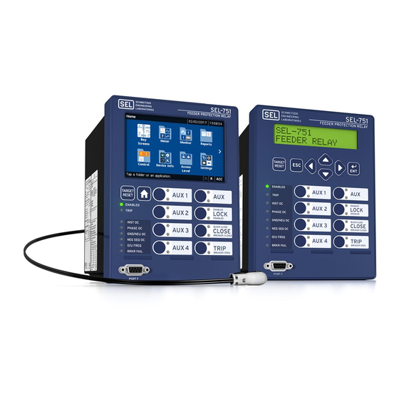
- Page 2 Slots A, B, C, D, E, and Z. Slots A, B, and Z are base unit slots, each associated with a specific function. Optional digital/analog I/O cards are available for the SEL-751 in Slots C, D, and E. Optional communications cards are available only for Slot C, an RTD card is available only for Slot D, 1 A/5 A/200 mA CT combinations for voltage/current or current only cards are available only on Slot Z, and a voltage/arc-flash card is available for Slot E.
- Page 3 to terminals A01+ and A02–, and reconnect the ground wire to the green 10. Apply power supply voltage ground screw. If you have a two-line display front panel, perform Step 11 through Step 19; if you have a touchscreen display front panel, proceed to Step 20. 11.
- Page 4 Also, contact SEL for an updated product serial number label with the updated part number.
- Page 5 13. Issue the STA C command to reboot the relay. 14. Issue the STA command to verify that the serial and part numbers of your relay are correct. Slot A Power Supply Card If you are replacing the power supply card, change the part number accordingly using the PARTNO command from Access Level C.
- Page 6 2011–2018 Schweitzer Engineering Laboratories, Inc. All rights reserved. All trademarks are the property of their respective holders. SEL products appearing in this document may be covered by U.S. and foreign patents. The information in this document is provided for informational use only and is subject to change without notice.
Need help?
Do you have a question about the SEL-751 and is the answer not in the manual?
Questions and answers
can a SEL-2240 take a 3-phase current signal from a SEL 751
YES. The SEL-2240 Axion can accept a 3-phase current signal from a SEL-751 relay when properly configured with compatible input modules and wiring for current inputs.
This answer is automatically generated
SEL-751 and SEL- 2240 connected to 3cts