Table of Contents
Advertisement
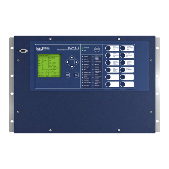
SEL-487E-3, -4 Transformer
Protection Relay
Three-Phase Transformer Protection,
Automation, and Control System
Key Features and Benefits
The SEL-487E Transformer Protection Relay provides three-phase differential protection for transformer applications
with as many as six three-phase restraint current inputs. A second three-phase differential element is also supported for
busbar protection.
➤
High-Speed Differential Protection. A two-stage slope adapts automatically to external fault conditions, providing
fast, sensitive, dependable, and secure differential protection, even for CT saturation and heavily distorted waveforms.
Two independent differential zones are available, one of which supports additional features that accommodate
transformer differential protection.
➤
Inrush and Overexcitation Detection. Combined harmonic blocking and restraint features provide maximum
security during transformer magnetizing inrush conditions. Waveshape-based inrush detection addresses inrush
conditions that contain low second and fourth harmonic content.
➤
Turn-to-Turn Winding Fault Protection. Innovative negative-sequence differential elements provide transformer
windings protection from as little as two percent turn-to-turn winding faults.
➤
Restricted Earth Fault Protection. Three independent REF elements provide sensitive protection for faults close
to the winding neutral in grounded wye-connected transformers.
Schweitzer Engineering Laboratories, Inc.
SEL-487E-3, -4 Data Sheet
Advertisement
Table of Contents

Subscribe to Our Youtube Channel
Related Manuals for Sel SEL-487E-3


Summary of Contents for Sel SEL-487E-3
- Page 1 Automation, and Control System Key Features and Benefits The SEL-487E Transformer Protection Relay provides three-phase differential protection for transformer applications with as many as six three-phase restraint current inputs. A second three-phase differential element is also supported for busbar protection.
- Page 2 Alarm contacts provide notification of substation battery voltage problems (as many as two independent battery monitors in some SEL-400 series relays) even if voltage is low only during trip or close operations. ➤...
- Page 3 IEEE 1588, Precision Time Protocol (PTP). PTP provides high-accuracy timing over an Ethernet network. ➤ Digital Relay-to-Relay Communications. M communications can monitor internal element conditions IRRORED between bays within a station, or between stations, using SEL fiber-optic transceivers. Send digital, analog, and virtual terminal data over the same M channel. IRRORED ➤...
-
Page 4: Functional Overview
O87P and falling in the operate region of Figure 2, the filtered differential element issues an output. There In the SEL-487E, the phase differential elements employ are two slope settings, namely Slope 1 (SLP1) and Slope 2 operate (IOPn, where n = A, B, C) and restraint (IRTn) (SLP2). -
Page 5: Distance Elements
Volts/Hertz (%) compared to the remainder of the unaffected winding. To detect these destructive internal faults, the SEL-487E uses a Figure 3 Volts/Hertz Curve Diagrams sensitive negative-sequence current differential element. This element detects the phase-current unbalance caused Distance Elements by internal fault by using a single-slope characteristic. -
Page 6: Out-Of-Step Detection
In addition to the selectable operate quantity, the 51S ele- time. This logic blocks the distance elements in case of a ment time-delay and pickup level inputs are SEL OGIC stable power swing. -
Page 7: Synchronism Check
X, Y). and minimize system coordination times. When voltage inputs are provided to the SEL-487E, voltage- based protection elements and frequency tracking are made available. Frequency tracking from 40.0 to 65.0 Hz Schweitzer Engineering Laboratories, Inc. -
Page 8: Distance Protection
GSU transformer in prime power, standby, base load, and peak Figure 9 Transmission Line Distance Application shaving applications. Figure 7 shows the SEL-487E in a typical GSU application. Six Terminal Feeder Protection Use the six three-phase current terminals on the SEL-487E... -
Page 9: Additional Features
(12 Pushbutton, 24 Target LED Option) Figure 12 and Figure 13 show close-up views of the front panel of the SEL-487E. The front panel includes a 128 x 128 pixel, 3" x 3" LCD screen; LED target indicators; and pushbuttons with indicating LEDs for local control func-... - Page 10 Q:99999.9 MV F:99.9 HZ Figure 14–Figure 17 are examples of some of the select- able one-line diagrams in the SEL-487E. Select the one- line diagram from the Bay settings. Additional settings NAVIG for defining labels and analog quantities are also found in the Bay settings.
-
Page 11: Alarm Points
Figure 18 Screens for Circuit Breaker Selection Rack-Type Breakers Mosaics slide-in label set is included with the SEL-487E. You can use templates supplied with the relay or hand label sup- plied blank labels and print label sets from a printer. -
Page 12: Communications Features
Use popular Telnet applications for easy terminal com- ➤ Access to event history, relay status, and meter munications with SEL relays and other devices. Transfer information from the communications ports. data at high speeds for fast file uploads. The Ethernet ➤... -
Page 13: Sntp Time Synchronization
➤ As many as 64 remote analog outputs. Assign the remote analog outputs to virtually any analog quantity available in the relay. You can also use SEL OGIC Use PRP to provide seamless recovery from any single math variables to develop custom analog quantities Ethernet network failure, in accordance with IEC 62439-3. - Page 14 Data are checksum protected. Extended Fast Meter, Fast Binary protocol for machine-to-machine communications. Quickly updates SEL-2032 Communications Pro- Operate, and Fast SER cessors, RTUs, and other substation devices with metering information, bay element, I/O status, time-tags, open and close commands, and summary event reports.
- Page 15 Outstation relay summary event reports, and settings groups. IEEE C37.118 Phasor measurement protocol. SEL protocol for exchanging digital and analog information among SEL relays and for use as low-speed termi- IRRORED nal connection. IEC 61850 Ethernet-based international standard for interoperability between intelligent devices in a substation.
-
Page 16: Metering And Monitoring
(ST, TU, UW, WX), 3I0, I1, 3I2 A, B, C RMS Currents RMS currents include fundamental plus all measurable harmonics. (S, T, U, W, X, Y) A, B, C (ST, TU, UW, WX) A, B, C SEL-487E-3, -4 Data Sheet Schweitzer Engineering Laboratories, Inc. -
Page 17: Event Summary
Reports are stored in nonvolatile memory. ➤ Event number Relay settings operational in the relay at the time of the ➤ Time source event are appended to each event report. ➤ Active settings group Schweitzer Engineering Laboratories, Inc. SEL-487E-3, -4 Data Sheet... - Page 18 Figure 24 Breaker Contact Wear Curve and Settings The relay measures and reports the substation battery Transformer Thermal Monitoring voltage for up to two battery systems. The SEL-411L, SEL-421, SEL-451 support two battery monitors while Transformer thermal monitoring for mineral-oil immersed the SEL-487B, SEL-487E, and SEL-487V support one.
-
Page 19: Through-Fault Event Monitor
The A through fault is an overcurrent event external to the SEL-487E through-fault report also provides percent of differential protection zone. Though a through fault is total through-fault accumulated according to the IEEE... - Page 20 MONITOR POWER 19 20 21 22 23 24 Vdc 1 + — + — 196–1747.A 19 20 21 22 23 24 196–1734.A Figure 28 5U Rear Panel, Main Board, LEA Voltage Option SEL-487E-3, -4 Data Sheet Schweitzer Engineering Laboratories, Inc.
- Page 21 Figure 29 6U Rear Panel, Main Board, Connectorized Option With One (INT2) I/O Board MONITOR POWER Vdc 1 + — — 196–1202.B 196–1203.D Figure 30 7U Rear Panel, Main Board, Terminal Block Option With Two (INT4) I/O Boards Schweitzer Engineering Laboratories, Inc. SEL-487E-3, -4 Data Sheet...
- Page 22 TIME IRIG-B MONITOR POWER Vdc 1 + — — 196–1202.B 196–1203.D Figure 31 9U Rear Panel, Main Board, Terminal Blocks Option With Four (INT4) I/O Boards SEL-487E-3, -4 Data Sheet Schweitzer Engineering Laboratories, Inc.
-
Page 23: Models And Options
1 A or 5 A, and the Y-windings either 1 A Automation Control.” On the SEL-487E-4, the front or 5 A on a per-phase basis, the SEL-487E supports only overlay reads “Station Phasor Measurement Unit.” All the combinations shown in Table 5. - Page 24 I/O requirements when installing the Winding IY1, IY2, IY3 = 5 A, 5 A, 5 A SEL-487E at power plants, transmission and distribution networks. You can install the interface boards in any combination in the relay. Table 6 provides I/O informa- tion about the main board and the four interface boards.
-
Page 25: Specifications
➢ Standard plus IEC 61850 Specifications One-Cycle Thermal Rating Note: TiDL (EtherCAT) technology is no longer offered in the SEL-487E-3, -4. TiDL (T-Protocol) is available in the SEL-487E-5. If the relay is using a 5 A Nominal: 1250 A-peak TiDL (EtherCAT) system, such as TiDL, the operating times will be delayed... - Page 26 125 Vdc 10.0 A L/R = 40 ms Dropout <53.0 Vac rms 250 Vdc 10.0 A L/R = 20 ms Note: Do not use hybrid control outputs to switch ac control signals. SEL-487E-3, -4 Data Sheet Schweitzer Engineering Laboratories, Inc.
-
Page 27: Type Tests
Logic Low Threshold: 3.6 kVdc for 1 min: Power Supply, Input Impedance: >1 k Battery Monitors Dielectric Test Voltage: 0.5 kVac 2.2 kVdc for 1 min: IRIG-B 1.1 kVdc for 1 min: Ethernet Schweitzer Engineering Laboratories, Inc. SEL-487E-3, -4 Data Sheet... -
Page 28: Reporting Functions
Binary COMTRADE communications ports shall be less than 10 m in length for Zone B compliance. Note: Per IEEE C37.111-1999 and IEEE C37.111-2013, Common Format for Transient Data Exchange (COMTRADE) for Power Systems. SEL-487E-3, -4 Data Sheet Schweitzer Engineering Laboratories, Inc. -
Page 29: Processing Specifications
0.1 A secondary (Minimum sensitivity is controlled by the Pickup Time 0.7 minimum cycle pickup of the supervising phase-to-phase (Filtered Unrestraint): 0.85 typical cycle overcurrent elements for each zone.) 1.2 maximum cycle Schweitzer Engineering Laboratories, Inc. SEL-487E-3, -4 Data Sheet... - Page 30 OFF, 0.05 to 150 secondary, 0.01 steps 5 A Model: Timer Accuracy: ±0.25 cycle plus ±0.1% of setting OFF, 0.25 to 750 secondary, 0.01 steps 1 A Model: Maximum Pickup/Dropout Time: 1.5 cycles SEL-487E-3, -4 Data Sheet Schweitzer Engineering Laboratories, Inc.
- Page 31 Pickup Range, Undervoltage 20.00–200.00 V (Wye) or V (Open- ±0.05 secondary Accuracy: Blocking: Delta) Transient Overreach: +5% of set reach Pickup Accuracy, Undervoltage Blocking: ±2% ±0.5 V Max. Delay: 1.75 cycles Schweitzer Engineering Laboratories, Inc. SEL-487E-3, -4 Data Sheet...
-
Page 32: Metering Accuracy
, 33.5–300 Vac, PF = 1, 0.5 lead, lag (1) 1.5 seconds (element dc ripple) Operating Time: ±0.7% (0.1–1.2) • I , 33.5–300 Vac, PF = 1, 0.5 lead, lag (3) 1.5 cycles (all elements but dc ripple) SEL-487E-3, -4 Data Sheet Schweitzer Engineering Laboratories, Inc. -
Page 33: Technical Support
Synchrophasor Protocol: IEEE C37.118-2005, SEL Fast Message (Legacy) Technical Support We appreciate your interest in SEL products and services. If you have questions or comments, please contact us at: Schweitzer Engineering Laboratories, Inc. 2350 NE Hopkins Court Pullman, WA 99163-5603 U.S.A.... - Page 34 Notes SEL-487E-3, -4 Data Sheet Schweitzer Engineering Laboratories, Inc.
- Page 35 Schweitzer Engineering Laboratories, Inc. SEL-487E-3, -4 Data Sheet...
- Page 36 All brand or product names appearing in this document are the trademark or registered trademark of their respective holders. No SEL trademarks may be used without written Tel: +1.509.332.1890 • Fax: +1.509.332.7990 permission. SEL products appearing in this document may be covered by U.S. and Foreign selinc.com • info@selinc.com patents.
Need help?
Do you have a question about the SEL-487E-3 and is the answer not in the manual?
Questions and answers