Table of Contents
Advertisement
Quick Links
Application Guide
Setting Up Maintenance Mode in an SEL-751
I
NTRODUCTION
Many users prefer to enable maintenance mode in relays as an added safety when working on ener-
gized equipment. The maintenance mode function, when activated, enables a sensitively set instan-
taneous overcurrent element for faster tripping in those relays without arc-flash protection and
prevents closing of the breaker by any means (e.g., automatic reclose, remote SCADA close, or
local pushbutton close). This function is not included in the default settings of the SEL-751 Feeder
Protection Relay, but you can set it up by making a few settings changes. This application guide
shows the settings necessary to enable and disable maintenance mode in an SEL-751 by pressing a
front-panel pushbutton. The same logic can be used when setting up maintenance mode in an
SEL-751A Feeder Protection Relay as well.
E
D
NABLING AND
ISABLING
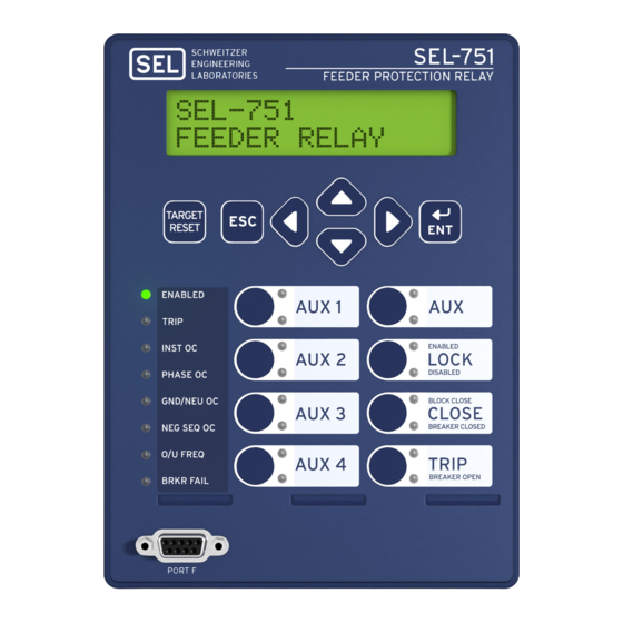
You can order the SEL-751 with either four or eight pushbuttons, as shown in Figure 1. This appli-
cation guide assumes that you have an SEL-751 with eight pushbuttons, that the relay is using the
default settings, and that the
the
pushbutton asserts the PB05 and PB05_PUL Relay Word bits as shown in Figure 1. The
AUX1
PB05 Relay Word bit remains asserted for as long as the pushbutton is pressed and is considered a
"follow" output. The PB05_PUL Relay Word bit asserts for only one processing interval (1/4 of a
power-system cycle) and then desserts, even if the button is still being pressed. Because we are
interested in capturing the moment the pushbutton is pressed and not in how long the pushbutton is
pressed, we use the PB05_PUL Relay Word bit in our logic. Note that instead of using the
pushbutton, you can use any other pushbutton to activate maintenance mode in your application.
Refer to Figure 1 and choose the Relay Word bit associated with the pushbutton that you are plan-
ning to use.
Next, we use the
maintenance mode. Figure 2 illustrates the settings. Latch Bit LT01 asserts (maintenance mode
off) when 1) the
front panel is not locked (LT02 = 1 per the default settings), and 3) the latch bit was previously
deasserted (maintenance mode on). Note that the front panel can be locked or unlocked by pressing
and holding the
tenance mode on) when 1) the
interval), 2) the front panel is not locked (LT02 = 1 per the default settings), and 3) the latch bit
was previously asserted (maintenance mode off).
Date Code 20200324
Swagata Das
M
M
AINTENANCE
ODE
pushbutton is being used to activate maintenance mode. Pressing
AUX1
pushbutton to drive Latch Bit LT01. The output of LT01 enables and disables
AUX1
pushbutton is pressed (PB05_PUL = 1 for one processing interval), 2) the
AUX1
pushbutton for 3 s (per the default settings). Latch Bit LT01 deasserts (main-
LOCK
pushbutton is pressed again (PB05_PUL = 1 for one processing
AUX1
Volume III
W
P
ITH A
USHBUTTON
AG2020-05
AUX1
SEL Application Guide 2020-05
Advertisement
Table of Contents

Related Manuals for Sel SEL-751


Summary of Contents for Sel SEL-751
- Page 1 ITH A USHBUTTON You can order the SEL-751 with either four or eight pushbuttons, as shown in Figure 1. This appli- cation guide assumes that you have an SEL-751 with eight pushbuttons, that the relay is using the default settings, and that the pushbutton is being used to activate maintenance mode.
- Page 2 URING AINTENANCE The arc-flash function in the SEL-751 provides the fastest tripping during a fault. It uses light and a fast overcurrent detector to detect faults within 2–5 ms [2] and can remain enabled at all times. This application guide shows an alternative method for faster tripping when the relay has not been ordered with arc-flash detection.
- Page 3 When directionality is disabled (EDIR = N), or when you have ordered the SEL-751 without directionality, the outputs of the phase instantaneous element are 50P2P (pickup) and 50P2T (time-delayed pickup). Note that the SEL-751A does not have directionality. The out- put of the phase instantaneous overcurrent logic in that relay is 50P2P and 50P2T.
- Page 4 Supervise the conditions listed in the close equation with LT01, as shown in Figure 6, so that the relay does not allow a close when maintenance mode is enabled. (...) AND LT01 Figure 6 Close Logic SEL Application Guide 2020-05 Date Code 20200324...
- Page 5 On the other hand, when PB5A_LED evaluates to logical 0, the LED turns off (O = OFF). The color of the bottom LED does not matter because it is not being used. Figure 8 Logic to Turn On Pushbutton LED During Maintenance Mode Date Code 20200324 SEL Application Guide 2020-05...
- Page 6 Flash LED To make the pushbutton LED flash during maintenance mode, set up a SEL variable as shown OGIC in Figure 9. Set the pickup and dropout delay to 0.5 s. These timers control how fast the LED flashes. Figure 9 Logic to Oscillate Timer Output Between 0 and 1 Change the PB5A_LED equation to NOT LT01 AND SV01T, as shown in Figure 10.
- Page 7 ABELS Once you change the settings, use the configurable label kit provided with the relay to update the operator control labels on the SEL-751 to avoid confusion. In this example, we changed the label for the PB05 pushbutton to , as shown in Figure 12.
- Page 8 [1] R. Kirby, “Reducing Arc-Flash Hazard Energy During Maintenance With an SEL-351S Front-Panel Pushbutton,” SEL Application Guide (AG2007-08), 2007. Available: selinc.com. [2] M. Zeller, D. Haas, and A. Hargrave, “Using the SEL-751 and SEL-751A for Arc-Flash Detection,” SEL Application Guide (AG2011-01), 2011. Available: selinc.com.
Need help?
Do you have a question about the SEL-751 and is the answer not in the manual?
Questions and answers