Sel -751A Express Installation Manual
Feeder protection relay
Hide thumbs
Also See for SEL-751A:
- Installation manual (9 pages) ,
- Instruction manual (641 pages) ,
- Instruction manual (4 pages)
Advertisement
For Additional Technical Assistance Call +1.509.332.1890
Express Installation Guide
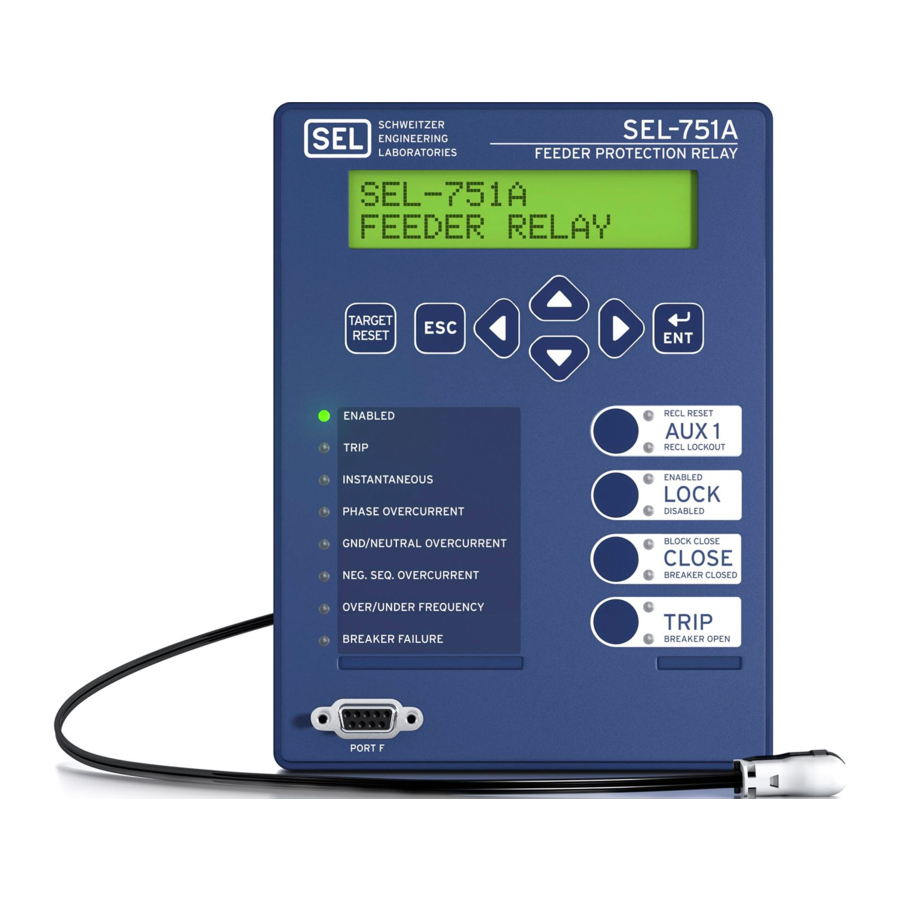
SEL-751A Feeder Protection Relay
Package Contents
Blank Pushbutton LED Label
Blank Target LED Label
Label Removal Tool
UP
UP
LEFT
198-0424
RIGHT
198–0424
Panel Cutout Template
Manual CD &
SEL
No. 8-32 Mounting Screws,
Configurable Label Kit
AC
ERATOR
®
QuickSet
Software CD
Gasket, & Serial Port Cover
(if equipped)
Courtesy of NationalSwitchgear.com
Advertisement
Table of Contents

Related Manuals for Sel SEL-751A


Summary of Contents for Sel SEL-751A
- Page 1 For Additional Technical Assistance Call +1.509.332.1890 Express Installation Guide SEL-751A Feeder Protection Relay Package Contents Blank Pushbutton LED Label Blank Target LED Label Label Removal Tool LEFT 198-0424 RIGHT 198–0424 Panel Cutout Template Manual CD & No. 8-32 Mounting Screws,...
- Page 2 110–250 Vdc IN101 IN102 OUT101 OUT103 CONTROL INPUTS INPUT POWER OUTPUT CONTACTS Front SEL-751A Feeder Protection Relay Port 3 (Optional Optional Input Output Cards 485) 10 RTDs IRIG-B Time Source IRIG-B Optional Ethernet (single or dual) 4 Digital Inputs / 4 Digital Outputs 1–12 RTDs...
- Page 3 Rack Mounting Mount the SEL-751A in a sheltered indoor environment (a building or an enclosed cabinet) that does not exceed the temperature rating of –40°C to +85°C. For mounting consideration, the relay dimensions are shown below. New Control Center 1. Place the enclosed Panel 2.
- Page 4 Connections Shown for the SEL-751A with Ethernet, Fiber Optic, IRIG-B, EIA-232, 4 DO/3 DI/1 AO Option, 8 DI Option, and Voltage Option. Refer to the SEL-751A manual for additional details and other options. Wire sizes for connections are dictated by the terminal blocks and expected load currents. You may use the following table...
- Page 5 Card Slot E: Voltage Inputs Card Connect 4-wire wye-connected PTs or open-delta connected PTs as shown in the typical connections diagram. For other PT connection options refer to Section 2 of the SEL-751A manual. Card Slot Z: Current Inputs Card Connect phase current and neutral current inputs as shown in the typical connections diagram.
- Page 6 There are three ways of communicating with the SEL-751A. You can communicate with the relay using the Human Machine Interface (HMI) on the front panel, remote communications, or a direct computer connection. For direct serial communications, the computer must have a serial port (or USB port if using SEL-C662 USB cable) and the operating sys- ®...
- Page 7 (if used) ratios and configurations, to match the feeder installation. The relay is equipped with a wide selection of protection and logic elements. Section 4 in the SEL-751A manual describes all the protection and logic functions of the relay, together with the necessary settings.
- Page 8 Step 4. Save the revised setting file into the database, and then with the settings still open, click the Send Active Settings icon and then click OK when prompted to upload the revised settings into relay. Step 5. Perform relay verification and commissioning tests per your requirements. Refer to Section 10 in the SEL-751A manual for details on relay testing. *PLS751A-01* ©...
Need help?
Do you have a question about the SEL-751A and is the answer not in the manual?
Questions and answers