
Subscribe to Our Youtube Channel
Related Manuals for Leuze electronic LPS


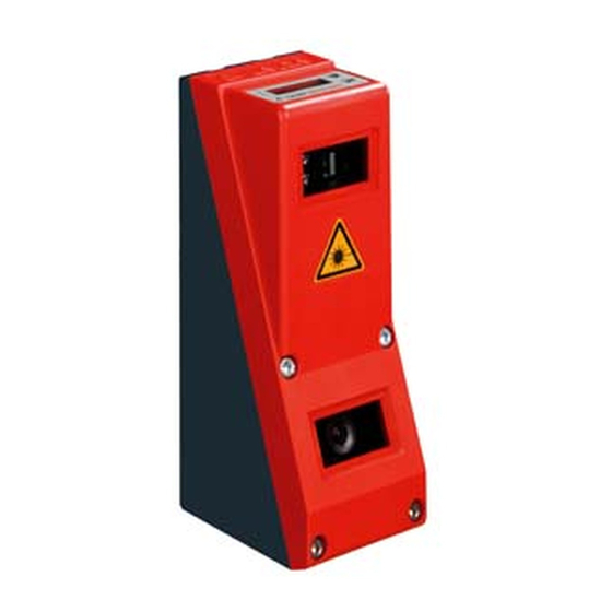
Summary of Contents for Leuze electronic LPS
- Page 1 LPS - Line Profile Sensor Light section sensors O r ig i n a l o p e r a t in g in s t r u c t io n s...
- Page 2 © 2018 Leuze electronic GmbH + Co. KG In der Braike 1 D-73277 Owen / Germany Phone: +49 7021 573-0 Fax: +49 7021 573-199 http://www.leuze.com info@leuze.com Leuze electronic LPS 36...
-
Page 3: Table Of Contents
Line Profile Sensor - LPS ........ - Page 4 Mounting the LPS ........
- Page 5 Typical procedure ..............70 Integrating the LPS in the process control (Ethernet) ..71 10.1...
- Page 6 Maintenance ........101 Leuze electronic LPS 36...
- Page 7 LPS ........
-
Page 8: Figures And Tables
Figure 9.2: Parameter settings in LPSsoft when LPS 36Hi is connected......62 Figure 9.3:... -
Page 9: Leuze Electronic Lps 36
Typical measurement range LPS 36HI ........ -
Page 10: General Information
Attention Laser! This symbol warns of possible danger through hazardous laser radiation. The light section sensors of the LPS series use a class 2M laser: Viewing the laser output with certain optical instruments, e.g. magnifying glasses, microscopes or binoculars, may result in eye damage. -
Page 11: Safety
This sensor was developed, manufactured and tested in line with the applicable safety stan- dards. It corresponds to the state of the art. Intended use The Light section sensors of the LPS series are laser distance sensors to determine 2D profiles. Areas of application... -
Page 12: Foreseeable Misuse
The device must not be tampered with and must not be changed in any way. The device must not be opened. There are no user-serviceable parts inside. Repairs must only be performed by Leuze electronic GmbH + Co. KG. Competent persons Connection, mounting, commissioning and adjustment of the device must only be carried out by competent persons. -
Page 13: Exemption Of Liability
BGV A3 (e.g. electrician foreman). In other countries, there are respective regula- tions that must be observed. Exemption of liability Leuze electronic GmbH + Co. KG is not liable in the following cases: • The device is not being used properly. • Reasonably foreseeable misuse is not taken into account. -
Page 14: Figure 2.1: Laser Apertures, Laser Warning Signs
Affix the laser information and warning signs so that they are legible without exposing the reader to the laser radiation of the device or other optical radiation. A Laser aperture B Laser warning sign C Laser information sign with laser parameters Figure 2.1: Laser apertures, laser warning signs Leuze electronic LPS 36... -
Page 15: Figure 2.2: Laser Warning And Information Signs - Supplied Stick-On Labels
8.7 mW Pulse duration: 3 ms 3 ms Wavelength: 658 nm 658 nm CLASS 2M LASER PRODUCT IEC 60825-1:2007 GB7247.1-2012 Complies with 21 CFR 1040.10 Figure 2.2: Laser warning and information signs – supplied stick-on labels Leuze electronic LPS 36... -
Page 16: Operating Principle
Depending on the distance of the object the laser line is projected to a different position on the CMOS planar detector as shown in Figure 3.1. By means of this position the distance of the object can be calculated. Leuze electronic LPS 36... -
Page 17: Limits Of Light Section Sensors
When the object is shifted to the left the object con- tour will still be detected by the laser but the laser line does not lie within the receiver's field of view at that point, and therefore no measurement values can be detected. Figure 3.2: Occlusion Leuze electronic LPS 36... -
Page 18: Possible Measure Against Laser Occlusion
In this situation the second sensor is then cas- caded. See "Cascading" on page 22. Leuze electronic LPS 36... -
Page 19: Resolution
Figure 3.3: Typical resolution LPS 36… The output resolution of the measurement values on the process interface is 1/10mm with Standard-Connect, 1/100mm with HI-Connect (only with LPS 36HI/EN). Object distance in Z-direction in mm Figure 3.4: Typical resolution LPS 36HI…... -
Page 20: Device Description
• Measurement range/detection area: LPS 36…: 200 to 800mm, LPS 36HI…: 200 to 600mm • Length of laser line: max. 600mm • Length of the laser line: LPS 36…: max. 600mm, LPS 36HI…: max. 140mm • Configuration and transmission of process data via Fast Ethernet • OLED display with membrane keyboard •... -
Page 21: Line Profile Sensor - Lps
Line Profile Sensor - LPS Wherever stationary or moving objects of various sizes and positions are to be measured or detected, the LPS sensor is used. 3D data are provided reliably due to precise 2D profile measurements in connection with mobile scan- ning. -
Page 22: Operating The Sensor
In measurement operation the Light section sensors are connected to a process control via the same X2 interface, and communicate with it via Ethernet (UDP), see chapter 10 "Inte- grating the LPS in the process control (Ethernet)". 4.2.2 Activation - laser on/off The laser and the data transmission can selectively be switched on and off via the activation input InAct (pin 2 at X1) or via the 'Ethernet Trigger' command. -
Page 23: Triggering - Free Running
- The shortest possible time interval between two successive trigger edges is 10ms. Note! fRun Ex works, the LPS is set to Free Running (shown on display: ). In order for it to respond to signals on the trigger input, the operating mode must be set via the LPSsoft con-... -
Page 24: Cascading
Sensor 1, or the master, can be operated in this case both triggered as well as continuously. All other sensors must be operated triggered. Cascading settings For all sensors except the last slave, the cascading output must be enabled via configuration software: Cascading Output: Enable. Leuze electronic LPS 36... -
Page 25: Inspection Task
Device description Inspection Task The LPS supports up to 16 individual inspection tasks. Grouped together in an inspection task are all parameter settings relevant for an application: • Operation Mode (Free Running, Input Triggered) • Activation Input (switch laser on and off) •... -
Page 26: Installation And Mounting
The following shows a light section sensor as an example. An overview of the available types may be found in Chapter 14.1 Figure 5.1: Device name plate LPS Save the original packaging for later storage or shipping. If you have any questions concerning your shipment, please contact your supplier or your local Leuze electronic sales office. -
Page 27: Mounting The Lps
Installation and mounting Mounting the LPS The Light section sensors can be mounted in different ways: • By means of two M4x6 screws on the back of the device • Using a BT 56 mounting device on the two fastening grooves. -
Page 28: Bt 56 Mounting Device
5.2.1 BT 56 mounting device The BT 56 mounting device is available for mounting the LPS using the fastening grooves. It is designed for rod mounting (Ø 16mm to 20mm). For order guide, please refer to chapter "Type overview and accessories" on page 106. -
Page 29: Bt 59 Mounting Device
Installation and mounting 5.2.2 BT 59 mounting device The BT 59 mounting device is available for mounting the LPS on ITEM profiles using the fastening grooves. For order guide, please refer to chapter "Type overview and accessories" on page 106. -
Page 30: Device Arrangement
• The optimal perspective for detecting the relevant contours of objects, see chapter 3.2.1 "Occlusion". Attention, laser radiation! When mounting and aligning the LPS, avoid reflections of the laser beam off reflective sur- faces! Note! The prevention of ambient light due to shielding of the sensor for example, ensures stable and precise measurement values. -
Page 31: Attach Laser Warning Sign
Light section sensor to the Light section sensor! If the signs would be concealed as a result of the mounting situation of the LPS, attach the signs in the vicinity of the LPS such that reading the signs cannot lead to looking into the laser beam! When installing the LPS in North America, also attach the stick-on label saying "Complies... -
Page 32: Electrical Connection
An overview of the available types may be found in Chapter 14.1 Figure 6.2: Connections of the LPS The pin assignment of X1 and X2 is identical for all Light section sensors; X3 and X4 differ depending on device type. -
Page 33: Safety Notices
Light section sensor. The housing of the LPS contains no parts that need to be adjusted or maintained by the user. Before connecting the device, be sure that the supply voltage agrees with the value printed on the name plate. -
Page 34: Shielding And Line Lengths
(grounding strip, …). If the LPS does not yet have an FE screw of its own, please use one of the M4 holes on the dovetail. -
Page 35: General Shielding Information
Carefully ground all parts of the machine and of the switch cabinet using copper strips, ground rails or grounding cables with large cross section. Below, the EMC-compliant connection of the Light section sensors LPS is described in prac- tical use with images. -
Page 36: Connecting The Cable Shielding In The Switch Cabinet
• Mounting rails must be well grounded Comment: Depicted shield components from Wago, series 790 ...: - 790-108 Shield clamping bracket 11 mm - 790-112 Carrier with grounding foot for TS35 Figure 6.5: Connecting the cable shielding to the PLC Leuze electronic LPS 36... -
Page 37: Connecting
The trigger input is used for synchronizing the measurement with the process and for synchronizing cascaded sensors. Further information can be found in Chapter 4.2.3 and Chapter 4.2.4. The internal equivalent circuit is shown in Figure 6.6. Leuze electronic LPS 36... -
Page 38: Cascading Output Outcas
LED (see "LED status indicators" on page 42). 6.3.2 Connection X2 - Ethernet Attention! All cables must be shielded! The LPS makes either the Ethernet interface available as host interface. X2 (4-pin socket, D-coded) Name Core color Comment... -
Page 39: Connection X3 - Incremental Encoder
6.3.3 Connection X3 - incremental encoder The LPS 36/EN and LPS 36HI/EN are equipped with an interface for an incremental encoder. Differential signals (5V) or 24V signals against GND can be processed. For reasons of inter- ference rejection, differential connection is recommended. - Page 40 Quadruple Mode (count all four edges on both encoder channels). • Counter Value Overflow: 0xFFFF FFFF Previously: 0xFEFF FFFF, the new Counter Overflow value 0xFFFF FFFF permits distance calculation in Double Mode with 32-bit values without manual correction. Leuze electronic LPS 36...
-
Page 41: Two-Channel Incremental Encoder With Open Collector Outputs
LPS 36 / EN +5V/24V Channel A: Example of NPN output Channel B: Example of PNP output Voltage supply for the incremental encoder is provided by the LPS Figure 6.8: Two-channel incremental encoder connection: example with NPN/PNP open collector Two-channel incremental encoder, single-ended... -
Page 42: Two-Channel Incremental Encoder, Differential
LPS 36 / EN +5V/24V Voltage supply for the incremental encoder is provided by the LPS Figure 6.10: Two-channel incremental encoder connection: differential - RS 422 example In general, it is recommended to use incremental encoders with RS 422 interface and 24V supply. -
Page 43: Single-Channel Incremental Encoder (Beginning With Firmware V01.20)
+5V/24V direction Voltage supply for the incremental encoder is provided by the LPS Figure 6.11: Single-channel incremental encoder connection: single-ended example (schematic illustration) Single-channel encoders have only one output channel (here clock - channel A). As a result, it is generally only possible to detect the movement, not, however, the direction of movement (counting). -
Page 44: Display And Control Panel
Indicator and operating elements of the LPS After switching on the supply voltage +U and following error-free initialization of the device, the green LED illuminates continuously: the LPS is in measure mode. The OLED display shows the alignment aid and the status display. 7.1.1... -
Page 45: Indicators In The Display
(no laser line, see chapter 4.2.2 "Activation - laser on/off"). Command mode If the LPS is connected to a control, the control can put the LPS into a command mode in which it receives and executes commands (see chapter 10.3 "Ethernet commands"). In command mode, the OLED display has one line. -
Page 46: Menu Description
Device Settings Device Settings menu item Error Handling Ethernet Ethernet interface parameters Data output IP Address IP address of the sensor 192.168.060.003 IP Address Setting for the IP address 192.168.060.003 (default: 192.168.060.003) Table 7.2: Menu structure Leuze electronic LPS 36... - Page 47 Error Handling menu item Info Reset to Factory Reset to factory settings Cancel Reset to Factory Do not execute reset Cancel Reset to Factory Execute reset with subsequent confirma- Execute tion prompt Table 7.2: Menu structure Leuze electronic LPS 36...
- Page 48 This parameter is used to reduce the measurement rate (data reduction), value range: 1 … 999 Note! If no button is pressed for three minutes, the LPS exits menu mode and switches to measure mode. The OLED display again displays the alignment aid and the sensor status display.
-
Page 49: Operation/Navigation
192.168.001.111 rejects the new value(in this example, the factory setting 192.168.060.003 remains saved) Editing selection parameters displays the next option for Display (Off). Display returns to the next-higher menu level and retains On. Leuze electronic LPS 36... -
Page 50: Reset To Factory Settings
Execute Interrupting a reset Pressing causes the adjacent display to appear. If you now press the FactorySettings Execute button, you will exit the menu without resetting the LPS to factory settings. Executing a reset Pressing the... -
Page 51: Commissioning And Configuration
In order to be able to establish an UDP communication with the PC, the IP address of your PC and the IP address of the LPS must lie in the same address range. The LPS has no built- in DHCP client, so that you need to set the address manually. This is done the easiest way via the PC. -
Page 52: Setting The Default Gateway
Close the configuration dialog by confirming all windows using OK Connect the interface X2 of the LPS directly to the LAN port of your PC. Use a KB ET-…-SA-RJ45 cable for the connection, see Table 14.10 The PC first tries to establish a network connection via the automatic configuration. This takes a few seconds, after which the alternate configuration, which you just set, is activated. -
Page 53: Commissioning
If you would like to set different values, you must change the values via the display of the LPS in menu item Ethernet (see "Menu description" on page 44). You can test the changed values by entering them in the Configuration area in LPSsoft and then clicking the Check Connectivity button. -
Page 54: Lpssoft Configuration Software
In the next window, you can select which configuration software you would like to install. You will need LPSsoft for configuring light section sensors of the LPS series. You will need LRSsoft for configuring light section sensors of the LRS series. - Page 55 LPSsoft configuration software Leuze electronic LPS 36...
- Page 56 LPSsoft configuration software Depending on the configuration of your Windows system, the dialog shown below may then appear (missing component VCREDIST_X86). Click on Install. Two additional installation windows will appear, which do not require any further entry. Leuze electronic LPS 36...
- Page 57 After some time (up to several minutes depending on the system configuration) the start screen of the MCR installer will appear. Click on Next. The window for entering user data appears. Enter your name and the company name and then click on Next. Leuze electronic LPS 36...
- Page 58 Click on Next and in the next window click on Install. The installation will start and a status window will be displayed. This can again take several minutes. Following successful MCR installation, the InstallShield Wizard Completed window appears. Click on Finish to end the MCR-installation. Leuze electronic LPS 36...
- Page 59 Keep the default folder in this case as well and click on Next. Upon completion of the installation process, the window shown above appears. The installation routine added a new Leuze electronic program group in your Start menu that contains the installed programs LPSsoft/LPSsoft/LRSsoft.
-
Page 60: Possible Error Message
Then click on OK and close also all further windows using OK. Shut Windows down, restart Windows and then start LPSsoft by double-clicking on it. Now the start screen of LPSsoft appears, as described in Chapter 9.3. Leuze electronic LPS 36... -
Page 61: Device List Update
9.2.2 Device list update At the time of purchase of a new sensor, the LPS/LES/LRS software corresponds to the state of the art. If you are already using software from earlier devices and now purchase a different model from the LxS series, it is possible that the installed software does not yet recognize the current device. -
Page 62: Starting Lpssoft/Communication Tab
Figure 9.1: Initial screen LPSsoft In the IP Configuration area, enter the settings for the LPS and click on Accept. You had already determined this data in Chapter 8.2. Click on Check Connectivity to test the connection to the LPS. - Page 63 • Sensor connection status (Sensor status) • Number of the Active Inspection Task • Scan number (Profile Number) • Encoder value dependent on the sensor type (Encoder Value) • Connected sensor type • Analog output status (Analog Output) Leuze electronic LPS 36...
-
Page 64: Parameter Settings/Parameters Tab
Click on the Parameters tab to access the parameter settings: Figure 9.2: Parameter settings in LPSsoft when LPS 36Hi is connected In the Standard tab, a median-3-filter can be activated in the Standard Parameters area. By activating the median filter in the checkbox, the Z-coordinates of the measurement values are smoothed out, while occurring edges are retained. -
Page 65: Operation Mode
Then try to achieve a line on a flat surface that is as continuous as possible. Field of View Using Field of View you can restrict the measurement range of the LPS. The same happens if you click on the square handles of the measurement range framed in blue with the mouse and then pull. -
Page 66: Apply Settings
Configuration -> Transmit to Sensor. 9.4.2 Encoder tab - Encoder Parameters area With the LPS 36/EN and LPS 36HI/EN, you can configure the model and the characteristics of the connected encoder in the Encoder tab. Figure 9.3: Encoder settings... -
Page 67: Evaluation Mode
Quadruple Mode (count all 4 edges on both encoder channels). • Counter Value Overflow: 0xFFFF FFFF Previously: 0xFEFF FFFF, the new Counter Overflow value 0xFFFF FFFF permits distance calculation in Double Mode with 32-bit values without manual correction. Leuze electronic LPS 36... -
Page 68: Measurement Function/Visualization Tab
• The Rotate 3D tool on the toolbar enables free and arbitrary rotation of the 3D view. In the 2D view you can view precise measurement values at individual points of the laser line using the Data Cursor tool. Leuze electronic LPS 36... -
Page 69: Evaluating Saved Measurement Data
Using the Profile Selection slider you can configure which of the displayed single data sets (profiles) from the 3D view will be shown in 2D view. The associated data set number is displayed under Profile No. The Show Plane option displays this single data set also in 3D view. Leuze electronic LPS 36... -
Page 70: Menu Commands
• Transmit to Sensor permanently stores all parameter settings of all defined inspection tasks from the configuration software in the LPS. • Reset to factory settings resets the LPS to factory settings. 9.6.3 Saving measurement data/Measure Records menu... -
Page 71: Zoom And Pan/Toolbar
The enlarged section can then be shifted with the activated hand function to display the area of interest. Note! The click-and-drag method for zooming known from other programs is not possible here. Before LPSsoft is operated further, the tool buttons (Zoom, Pan, …) must be activated. Leuze electronic LPS 36... -
Page 72: Definition Of Inspection Tasks
Display and, if necessary, enlarge 2D view of the detection range in the Parameters tab. Set LPS parameters (see "Standard tab - Task Parameters panel" on page 62) Assign a name (Name) to the inspection task and confirm with Accept. -
Page 73: Integrating The Lps In The Process Control (Ethernet)
Chapter 10.3. Note! If you use a firewall, please make certain that the control can communicate with the LPS via the Ethernet interface by means of UDP on ports 9008 and 5634 (these ports are preset at the factory, but may have been changed by the user, see chapter 7.2 "Menu description"). -
Page 74: Protocol Structure
Integrating the LPS in the process control (Ethernet) Protocol structure The protocol consists of the Header (30 bytes) followed by the User data. The protocol is used both in command mode when transmitting commands and when acknowledging sensor commands as well as in measure mode. -
Page 75: 10.2.2 Packet Number
Integrating the LPS in the process control (Ethernet) 10.2.2 Packet number The packet number serves internal maintenance purposes of the manufacturer. 10.2.3 Transaction number In measure mode, 0x0000 is always displayed here. In command mode, the command acknowledgment of the sensor contains the command number of the command that is answered. -
Page 76: 10.2.5 Encoder High / Low
X-data (command number 0x5858), each with 376 values of 2 bytes, are transmitted. With the LPS 36HI/EN, values 241 … 376 are set to 0 (compatibility). The resolution is 1/10mm. The Z- and X-data packets have the same scan number; this should be checked in the control. - Page 77 -7000 … +7000 range. Invalid measurement values have a Z- and X-value of 0. If an LPS 36HI/EN is used in a system instead of an LPS 36 without the establishment of connection being changed (Standard-Connect), it behaves compatibly to the stan- dard LPS 36.
-
Page 78: Ethernet Commands
The response of the LPS also corresponds to the "little-endian" standard. For further information, see the note in Chapter 10.2. Note! If the LPS is operated in command mode, the LPS transmits no data (useful for operation with PLC controls). In measure mode, commands Connect to Sensor, Disconnect from Sensor, Enter Command mode, Ethernet Trigger and Ethernet Activation can be processed (is acknowledged with 'Ack'=0x4141). -
Page 79: 10.3.1 Elementary Commands
Command syntax (header/user data), see Chapter 10.2 Using the Connect to sensor and Disconnect from sensor commands, a connection between control and sensor is established or terminated. The communication with the LPS is carried out via the ports previously configured in LPSsoft. - Page 80 Integrating the LPS in the process control (Ethernet) If the LPS 36HI is connected with the Connect to Sensor command and a user data value of 0x0001, then the sensor is connected via HI-Connect. Command from control to LPS Answer from LPS to control Command no.
-
Page 81: 10.3.2 Commands In Command Mode
Integrating the LPS in the process control (Ethernet) 10.3.2 Commands in command mode Note! Command syntax (header/user data), see Chapter 10.2 The following commands are available in command mode: Command from control to LPS Answer from LPS to control Num-... - Page 82 Table 10.4: Sensor control commands Command cannot be processed up to firmware V01.26 if the LPS is set to "Input Triggered" Operation Mode (see chapter 9.4.1 "Standard tab - Task Parameters panel", Operation Mode on Page 62). Commands 0x0011 and 0x0013 can be transmitted no sooner than 30ms after command 0x0003 in order to obtain valid measurement data.
-
Page 83: Explanation Of User Data In Command Mode (Command Parameters)
Integrating the LPS in the process control (Ethernet) The command acts globally on all inspection tasks. Attention! If the command is used to deactivate the output of X-coordinates, only Z-coordinates are transmitted. LPSsoft Can be used to depict 2D- and 3D-views. The sensor can only be reset to again transmit X- and Z-coordinates by means of command number 0x0059 when using parameter ID 0x07D4. -
Page 84: Set Actual Inspection Task
SF = SaveFlag If SF=0 then the inspection task is changed only temporarily. If SF=1 then the newly set inspection task is retained even after a restart of the LPS. Get Actual Inspection Task The LPS responds to sensor control command 0x0049 with 0x004A and one word of user... -
Page 85: Set Single User Parameter
(0 = 0.1ms … 9 = 1.0ms) If SF=0, the duration of the transmission pause is changed only temporarily. If SF=1, the duration of the transmission pause is retained even following a restart of the LPS. Note! If the transfer of X-coordinates is switched off in measure mode, no visualization of mea- surement data can be performed in the 2D- and 3D-views in LPSsoft. - Page 86 MF = Median filter If SF=0, the setting for the median filter is only temporary. If SF=1, the setting for the median filter is retained even after a restart of the LPS. If MF=0, the median filter is deactivated. If MF=1, the median filter is activated.
-
Page 87: Get Single User Parameter
Integrating the LPS in the process control (Ethernet) Get Single User parameter Status of the transmission of X-coordinates in measure mode When using parameter ID 0x07D4, sensor control command 0x005B can be used to check whether X-coordinates are output. Command syntax:... - Page 88 Integrating the LPS in the process control (Ethernet) Querying whether median filter is active/not active When using parameter ID 0x07DB, sensor control command 0x005B can be used to check whether the median filter is activated. When using sensor control command 0x005B with parameter ID 0x07DB, one word of user...
-
Page 89: Set Single Inspection Task Parameter
35…58 Parameter value[s] dependent on parameter ID Parameters and settings: If SF=0, then the parameter is changed only temporarily. If SF=1, the parameter is retained even following a restart of the LPS. Parameter ID Parameter meaning Valid parameter values Parameter... - Page 90 Integrating the LPS in the process control (Ethernet) Parameter ID Parameter meaning Valid parameter values Parameter Number of data type parameter val- 0x0BBE Manual adjustment of the exposure Permissible value range UINT16 duration LPS 36HI/EN: 739…13109; LPS 36, LPS 36/EN: 973…13109 (exposure time unit in 1/10μs).
-
Page 91: Get Single Inspection Task Parameter
• Setting of activation (Activation Input: Regard or Disregard) • Setting of cascading output (Cascading Output: Enable or Disable) • Exposure duration of the laser (Light Exposure) • Detection range of the LPS (Field of View). Byte High-Byte LSB MSB... - Page 92 Integrating the LPS in the process control (Ethernet) Meaning of the bits: Parameter ID Parameter meaning Valid parameter values Parameter data Number of type parameter val- 0x0BB8 Number of the active inspection task 0-15 UINT8 0x0BB9 Name of the active inspection task...
-
Page 93: 10.3.4 Commands In Measure Mode
Integrating the LPS in the process control (Ethernet) 10.3.4 Commands in measure mode Note! Command syntax (header/user data), see Chapter 10.2 The following commands are available in measure mode: Command from control to LPS Answer from LPS to control Num-... - Page 94 Integrating the LPS in the process control (Ethernet) Command from control to LPS Answer from LPS to control Num- Num- ber of ber of Com- Com- Meaning user Meaning user mand no. mand no. data data words words 0x4541 Ethernet Activation...
-
Page 95: Explanation Of User Data In Measure Mode (Command Parameters)
Integrating the LPS in the process control (Ethernet) 10.3.5 Explanation of user data in measure mode (command parameters) Ethernet Activation For sensor control command 0x4541, one word of user data is transmitted to the sensor: Byte High-Byte LSB MSB Low-Byte LSB Meaning of the bits 31…32... -
Page 96: Working With The Protocol
0x0000 0x0000 0x0000 0x434E 0x0000 0x0000 0x0000 0x0000 0x0000 0x0000 0x0000 Command with user data Set Actual Inspection Task (LPS in command mode, activate Task 15 and do not store in volatile memory) PC to LPS: 0xFFFF 0xFFFF 0x0000 0x004B... -
Page 97: Operation With Lxs_Lib.dll
The LxS_Lib.dll is a .NET 2.0-compatible collection of functions which considerably facili- tates the integration of all Leuze light section sensors (LPS, LRS and LES) into PC environ- ments. The LxS_Lib.dll can be used in a variety of programming languages, such as C#, Visual Basic, etc. -
Page 98: Operating With Halcon® Image Processing Software
(http://www.mvtec.com) can be used to evaluate the recorded 2D profiles. To simplify the data import step for the user, an Image Acquisition Interface is available that directly controls the LPS sensors and can read the measurement data (X, Z-coordinates and encoder values). -
Page 99: Diagnostics And Troubleshooting
Check settings of the Ethernet interface. Connect sen- sor to control Sensor not activated Activate sensor via PIN 2 on X1. Switch off activation input. See "Activation" on page 63. Table 11.1: General causes of errors Leuze electronic LPS 36... -
Page 100: Interface Error
Ethernet" on page 49. Incorrect port assigned to Using ping command check whether the sensor LPS / control responds. If so, check port assignment to LPS and control. The set ports must match. Firewall blocks ports Switch off firewall temporarily and repeat connection test. -
Page 101: Error Messages In Display (Starting From Firmware V01.40)
During this time, the sensor is not ready - this can be seen at: X1 pin 4: Out Ready and Ethernet protocol: "Status". The sensor starts automatically and is then ready again. An Ethernet connection must be re-established. Leuze electronic LPS 36... - Page 102 - File: LPSsoft.log (located in the installation directory of LPSsoft) - Parameter file *.lss; if applicable, screenshots, images, stored measurement data *.csv, etc. Leuze Service fax number: +49 7021 573 - 199 Leuze Service e-mail for the LOS product unit: service.erkennen@leuze.de Leuze electronic LPS 36...
-
Page 103: Maintenance
General maintenance information Usually, the Light section sensor does not require any maintenance by the operator. Cleaning In the event of dust buildup, clean the LPS with a soft cloth; use a cleaning agent (commer- cially available glass cleaner) if necessary. Note! Do not use aggressive cleaning agents such as thinner or acetone for cleaning the Light sec- tion sensors. -
Page 104: Technical Data
Technical data Technical data 13.1 General technical data LPS 36… LPS 36HI… Optical data Measurement range in X direction 200 … 600mm 46 … 140mm in Z direction 200 … 800mm 200 … 600mm Light source Laser Laser class 2M acc. to IEC 60825-1:2007... - Page 105 For UL applications: use is permitted exclusively in Class 2 circuits according to NEC The push-pull switching outputs must not be connected in parallel 1=transient protection, 2=polarity reversal protection, 3=short circuit protection for all out- puts Only if the connectors and caps are screwed into place Leuze electronic LPS 36...
-
Page 106: Typical Measurement Range
Technical data 13.2 Typical measurement range -300 X = line length -225 -150 Measurement range +150 +225 +300 Figure 13.1: Typical measurement range LPS 36 -100 Measurement range z-axis +100 Figure 13.2: Typical measurement range LPS 36HI Leuze electronic LPS 36... -
Page 107: Dimensioned Drawing
OLED display and membrane keyboard M4 thread, 4.5 deep Holder for mounting system BT 56 / BT 59 Zero point and orientation of the coordinate system for measurement data 4mm bore hole in transmitter axis Figure 13.3: LPS dimensioned drawing Leuze electronic LPS 36... -
Page 108: Type Overview And Accessories
Line profile sensor for profile generation, measurement range 200 … 800mm, 50138405 line length 600mm with Ethernet interface, plastic screen LPS 36 HI/EN Line profile sensor for profile generation, measurement range 200 … 600mm, 50111334 line length 140mm with Ethernet interface, incremental encoder connection LPS 36 HI/EN.10... -
Page 109: 14.1.3 Les
200 … 600mm, line length 140mm, Ethernet interface, analog current or voltage output, 4 switching outputs for detection information, 3 switching inputs for selection of the inspection task, plastic screen Table 14.3: LES type overview Leuze electronic LPS 36... -
Page 110: Accessories
500 27375 BT 59 Mounting device featuring dovetail for ITEM profile 50111224 Table 14.4: Mounting devices for the LPS 14.2.2 Accessories – Ready-made cables for voltage supply X1 Contact assignment for connection cable X1 Connection cable X1 (8-pin socket, A-coded) Name... -
Page 111: 14.2.3 Accessories For Ethernet Interface X2
KSS ET-M12-4A-RJ45-A-P7-020 Cable length 2m 50135080 KSS ET-M12-4A-RJ45-A-P7-050 Cable length 5m 50135081 KSS ET-M12-4A-RJ45-A-P7-100 Cable length 10m 50135082 KSS ET-M12-4A-RJ45-A-P7-150 Cable length 15m 50135083 KSS ET-M12-4A-RJ45-A-P7-300 Cable length 30m 50135084 Table 14.10: Ethernet connection cables M12 connector/RJ-45 Leuze electronic LPS 36... -
Page 112: Ready-Made Cables With M12 Connector/M12 Connector
Connectors Type designation Description Part no. D-ET1 RJ45 connector for user-configuration 50108991 KDS ET M12 / RJ 45 W - 4P Converter from M12, D-coded, to RJ 45 socket 50109832 Table 14.13: Connectors for the LPS Leuze electronic LPS 36... -
Page 113: 14.2.4 Accessories - Ready-Made Cables For X3
Cable length 2m 50135138 KS S-M12-8A-P1-050 Cable length 5m 50135139 KS S-M12-8A-P1-100 Cable length 10m 50135140 KS S-M12-8A-P1-150 Cable length 15m 50135141 KS S-M12-8A-P1-300 Cable length 30m 50135142 Table 14.15: X3 cables for the LPS 36/6 Leuze electronic LPS 36... -
Page 114: 14.2.5 Configuration Software
The configuration memory saves the configured inspection tasks as well as the setting of general parameters such as operating mode, activation, cascading, detection range (FoV), etc., from the connected sensor and transfers these to a new device following an exchange. Leuze electronic LPS 36... -
Page 115: Appendix
Distance and position progression of one or more measurements, coordinates of Profile data the respective X/Z-values when passing through the laser beam along the x-axis. 2D view Graphical presentation of the X/Z-coordinate values of an object within the detec- tion range. Leuze electronic LPS 36... -
Page 116: Revision History / Feature List
Beginning Multiple inspection tasks Up to 16 different configurations LxSsoft V1.20 (LPSsoft V1.20, with V01.10 for the LPS 36 can be stored in the sensor; LRSsoft V1.04) switch between configurations by means of a command Beginning Optimized encoder inter- LPS 36/EN: LxSsoft V1.20 (LPSsoft V1.20,... -
Page 117: 15.2.2 Configuration Software
Appendix Beginning Support of LPS 36HI/EN Additional device types LxSsoft V2.00 (LPSsoft V2.00, with V01.40 LPS 36HI/EN LESsoft V1.10, LRSsoft V1.20) New "Ethernet Activa- Switching on laser via Ethernet tion" command command New "Get/Set Single Parameter adjustment via Ether- Inspection Task Parame- net commands without LPSsoft ter"... - Page 118 EN device types LxSsoft V2.30 (LPSsoft V2.20, Import Inspection Task Settings of individual inspection tasks LESsoft V2.30, LRSsoft V2.20) can be imported from a saved LPS proj- LxSsoft V2.31 (LPSsoft V2.31, Documentation updated LESsoft V2.31, LRSsoft V2.31) LXSsoft V2.40 (LPSsoft V2.40,...
-
Page 119: Index
Electrical data Mutual interference Encoder Encoder count Environment variable Name plate Environmental data Error limits Error message Ethernet cable assignment Occlusion Ethernet connection OLED display Ethernet interface Optical data Evaluating measurement data Exposure duration Exposure setting Leuze electronic LPS 36... - Page 120 Pin assignment X3 Port 9008 Power supply Receiver occlusion Receiving optics Repair Resolution Rod mounting Saving measurement data Servicing Shielding System requirements System variable Time behavior Triangulation principle Trigger input Trigger time Trouble shooting Type overview Warmup time Leuze electronic LPS 36...
Need help?
Do you have a question about the LPS and is the answer not in the manual?
Questions and answers