Sign In
Upload
Manuals
Brands
Leuze electronic Manuals
Accessories
LPS
Leuze electronic LPS Manuals
Manuals and User Guides for Leuze electronic LPS. We have
1
Leuze electronic LPS manual available for free PDF download: Original Operating Instructions
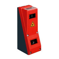
Leuze electronic LPS Original Operating Instructions (120 pages)
Line Profile Sensor. Light Section Sensors.
Brand:
Leuze electronic
| Category:
Accessories
| Size: 5 MB
Table of Contents
Table of Contents
3
Figures and Tables
8
Leuze Electronic LPS 36
9
1 General Information
10
Explanation of Symbols
10
Declaration of Conformity
10
2 Safety
11
Intended Use
11
Foreseeable Misuse
12
Competent Persons
12
Exemption of Liability
13
Laser Safety Notices
13
Figure 2.1: Laser Apertures, Laser Warning Signs
14
Figure 2.2: Laser Warning and Information Signs - Supplied Stick-On Labels
15
3 Operating Principle
16
Generation of 2D Profiles
16
Figure 3.1: Light Section Sensor Design
16
Limits of Light Section Sensors
17
Occlusion
17
Figure 3.2: Occlusion
17
Possible Measure against Laser Occlusion
18
Possible Measures against Receiver Occlusion
18
Resolution
19
Figure 3.3: Typical Resolution LPS 36
19
Figure 3.4: Typical Resolution LPS 36HI
19
4 Device Description
20
Overview of Light Section Sensors
20
Mechanical Design
20
General Performance Characteristics
20
Figure 4.1: Mechanical Design of Leuze Light Section Sensors
20
Line Profile Sensor - LPS
21
Specific Performance Characteristics
21
Typical Areas of Application
21
Operating the Sensor
22
Connection to PC / Process Control
22
Configuration
22
Measurement Operation
22
Activation - Laser On/Off
22
Figure 4.2: Activation Input Signal Sequence
22
Triggering - Free Running
23
Figure 4.3: Trigger Input Signal Sequence
23
Cascading
24
Trigger Settings
24
Cascading Settings
24
Figure 4.4: Signal Sequence for Cascading
24
Figure 4.5: Cascading Application Example
24
Inspection Task
25
5 Installation and Mounting
26
Storage, Transportation
26
Unpacking
26
Figure 5.1: Device Name Plate LPS
26
Mounting the LPS
27
Figure 5.2: Fastening Options
27
Figure 5.3: Mounting Example LPS
27
BT 56 Mounting Device
28
Figure 5.4: BT 56 Mounting Device
28
BT 59 Mounting Device
29
Figure 5.5: BT 59 Mounting Device
29
Device Arrangement
30
Selecting a Mounting Location
30
Aligning the Sensor
30
Attach Laser Warning Sign
31
Cleaning
31
Figure 5.6: Alignment to the Measuring Plane
31
6 Electrical Connection
32
Figure 6.1: Location of the Electrical Connections
32
Figure 6.2: Connections of the LPS
32
Safety Notices
33
Shielding and Line Lengths
34
Shielding
34
General Shielding Information
35
Connect the Ground Potential to the Light Section Sensors
35
Figure 6.3: Connecting the Ground Potential to the Light Section Sensor
35
Connecting the Cable Shielding in the Switch Cabinet
36
Connecting the Cable Shielding to the PLC
36
Figure 6.4: Connecting the Cable Shielding in the Switch Cabinet
36
Figure 6.5: Connecting the Cable Shielding to the PLC
36
Connecting
37
Connection X1 - Logic and Power
37
Power Supply
37
Activation Input Inact
37
Trigger Input Intrig
37
Figure 6.6: Internal Wiring at X1
37
Cascading Output Outcas
38
Output "Ready" Outready
38
Connection X2 - Ethernet
38
Ethernet Cable Assignment
38
Figure 6.7: HOST / BUS in Cable Assignments on RJ-45
38
Connection X3 - Incremental Encoder
39
Two-Channel Incremental Encoder with Open Collector Outputs
41
Two-Channel Incremental Encoder, Single-Ended
41
Figure 6.8: Two-Channel Incremental Encoder Connection: Example with NPN/PNP Open Collector
41
Figure 6.9: Two-Channel Incremental Encoder Connection: Single-Ended Example
41
Two-Channel Incremental Encoder, Differential
42
Figure 6.10: Two-Channel Incremental Encoder Connection: Differential - RS 422 Example
42
Single-Channel Incremental Encoder (Beginning with Firmware V01.20)
43
Figure 6.11: Single-Channel Incremental Encoder Connection: Single-Ended Example (Schematic Illustration)
43
7 Display and Control Panel
44
Indicators and Operational Controls
44
LED Status Indicators
44
Control Buttons
44
Figure 7.1: Indicator and Operating Elements of the LPS
44
Indicators in the Display
45
Alignment Aid
45
Status Indicator
45
Command Mode
45
Menu Description
46
Structure
46
Operation/Navigation
49
Menu Navigation
49
Selecting Values or Selection Parameters for Editing
49
Editing Value Parameters
49
Editing Selection Parameters
49
Reset to Factory Settings
50
Interrupting a Reset
50
Executing a Reset
50
8 Commissioning and Configuration
51
Switching on
51
Establish Connection to PC
51
Setting the Default Gateway
52
Setting an Alternative IP Address on the PC
52
Commissioning
53
9 Lpssoft Configuration Software
54
System Requirements
54
Installation
54
Possible Error Message
60
Device List Update
61
Starting Lpssoft/Communication Tab
62
Figure 9.1: Initial Screen Lpssoft
62
Parameter Settings/Parameters Tab
64
Standard Tab - Task Parameters Panel
64
Inspection Task Selection
64
Figure 9.2: Parameter Settings in Lpssoft When LPS 36Hi Is Connected
64
Operation Mode
65
Activation
65
Trigger Output Mode
65
Light Exposure
65
Field of View
65
Apply Settings
66
Encoder Tab - Encoder Parameters Area
66
Encoder Type
66
Figure 9.3: Encoder Settings
66
Evaluation Mode
67
Counter Value Overflow
67
Measurement Function/Visualization Tab
68
Figure 9.4: 3D Visualization with Lpssoft
68
Evaluating Saved Measurement Data
69
Figure 9.5: Evaluating Saved 3D Data
69
Menu Commands
70
Saving Parameter Settings/File Menu
70
Transmitting Parameter Settings/Configuration Menu
70
Saving Measurement Data/Measure Records Menu
70
Zoom and Pan/Toolbar
71
Figure 9.6: Zoom Function
71
Definition of Inspection Tasks
72
Typical Procedure
72
10 Integrating the LPS in the Process Control (Ethernet)
73
General Information
73
Protocol Structure
73
Protocol Structure
74
Header
74
User Data
74
10.2.1 Command Number
74
10.2.2 Packet Number
75
10.2.3 Transaction Number
75
10.2.4 Status
75
10.2.5 Encoder High / Low
76
10.2.6 Scan Number
76
10.2.7 Type
76
10.2.8 Number of User Data Words
76
10.2.9 User Data
76
Ethernet Commands
78
10.3.1 Elementary Commands
79
10.3.2 Commands in Command Mode
81
Explanation of User Data in Command Mode (Command Parameters)
83
Set Laser Gate
83
Set Encoder Value
83
Set Actual Inspection Task
84
Get Actual Inspection Task
84
Set Scan Number
84
Set Single User Parameter
85
Get Single User Parameter
87
Set Single Inspection Task Parameter
89
Get Single Inspection Task Parameter
91
10.3.4 Commands in Measure Mode
93
Explanation of User Data in Measure Mode (Command Parameters)
95
Ethernet Activation
95
Working with the Protocol
96
Command Without User Data
96
Command with User Data
96
Operation with Lxs_Lib.dll
97
Access
97
Operation with Native C++ DLL
97
Operating with HALCON® Image Processing Software
98
Benefits
98
Access
98
Additional Support When Integrating Sensors
98
11 Diagnostics and Troubleshooting
99
General Causes of Errors
99
Interface Error
100
Error Messages in Display (Starting from Firmware V01.40)
101
12 Maintenance
103
General Maintenance Information
103
Cleaning
103
Repairs, Servicing
103
Disassembling, Packing, Disposing
103
Repacking
103
13 Technical Data
104
General Technical Data
104
Typical Measurement Range
106
Dimensioned Drawing
107
14 Type Overview and Accessories
108
Type Overview
108
14.1.1 Lps
108
14.1.2 Lrs
108
14.1.3 Les
109
Accessories
110
14.2.1 Mounting
110
Mounting Devices
110
14.2.2 Accessories - Ready-Made Cables for Voltage Supply X1
110
Contact Assignment for Connection Cable X1
110
Order Codes of the Cables for Voltage Supply
110
14.2.3 Accessories for Ethernet Interface X2
111
Ready-Made Cables with M12 Connector/Open Cable End
111
Ready-Made Cables with M12 Connector/Rj-45 Connector
111
Ready-Made Cables with M12 Connector/M12 Connector
112
Connectors
112
14.2.4 Accessories - Ready-Made Cables for X3
113
Contact Assignment for X3 Connection Cables
113
Order Code of X3 Connection Cables
113
14.2.5 Configuration Software
114
14.2.6 Configuration Memory
114
15 Appendix
115
Glossary
115
Revision History / Feature List
116
15.2.1 Firmware
116
15.2.2 Configuration Software
117
Index
119
Advertisement
Advertisement
Related Products
Leuze electronic Line Profile LPS 36 Series
Leuze electronic LES Series
Leuze electronic LES 36/VC
Leuze electronic LES 36/VC6
Leuze electronic LES 36/PB
Leuze electronic LES 36
Leuze electronic LES 36 HI
Leuze electronic LCS-1M18P-F05PNP-M12-LT
Leuze electronic LCS-1M18P-F05NNP-M12-LT
Leuze electronic LCS-1M30P-F10PNP-M12-LT
Leuze electronic Categories
Accessories
Barcode Reader
Measuring Instruments
Security Sensors
Scanner
More Leuze electronic Manuals
Login
Sign In
OR
Sign in with Facebook
Sign in with Google
Upload manual
Upload from disk
Upload from URL