Advertisement
Quick Links
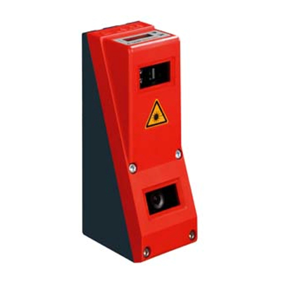
LES 36
200 ... 800mm
Light section sensor for object
measurement (width, height and position
measurement)
Measurement time 10ms
Measurement range: 200 ... 800mm
Length of laser line: max. 600mm
Integrated PROFIBUS interface or analog
output
Configuration via Fast Ethernet
OLED display with key pad for alignment
aid and status display: "set inspection task"
Measurement value display in mm on OLED
display as an alignment aid
Up to 4 measurement fields / 8 detection
fields with logic operation option
Up to 16 inspection tasks
Activation input, trigger input, cascading
output
PROFIBUS connection via Y adapter
IEC 60947...
IEC 60947...
Accessories:
(available separately)
Mounting systems BT 56, BT 59
Cable with M12 connector (K-D ...)
Configuration memory
K-DS M12A-8P-0,75m-LxS36-CP
Leuze electronic GmbH + Co. KG
info@leuze.com • www.leuze.com
Dimensioned drawing
+Z
A
B
C
D
E
F
G
H
J
K
L
M
Measurement range, typical
IP 67
In der Braike 1 D-73277 Owen Tel. +49 (0) 7021 573-0
Light section sensor for object measurement
+X
Transmitter
Receiver
Optical axis
X1: M12x1 connector, 8-pin, A coded
X2: M12x1 socket, 4-pin, D coded
X3: M12x1 socket, 8-pin, A coded (LES 36/VC6 only)
X4: M12x1 socket, 5-pin, B coded (LES 36/PB),
M12x1 socket, 5-pin, A coded (LES 36/VC, LES 36/VC6)
FE screw
OLED display and membrane keyboard
M4 thread, 4.5 deep
Holder for mounting system BT 56 / BT 59
Zero point and orientation of the coordinate system for measurement data
-x
-300
x = Line length in mm
-225
-150
-75
100
200
300
+75
+150
+225
+300
+x
-X
Measurement range
400
500
600
z = Object distance
+z
700
800
LES 36... - 04
Advertisement

Subscribe to Our Youtube Channel
Related Manuals for Leuze electronic LES 36


Summary of Contents for Leuze electronic LES 36
- Page 1 Configuration via Fast Ethernet X2: M12x1 socket, 4-pin, D coded OLED display with key pad for alignment X3: M12x1 socket, 8-pin, A coded (LES 36/VC6 only) aid and status display: "set inspection task" X4: M12x1 socket, 5-pin, B coded (LES 36/PB), ...
-
Page 2: Specifications
1 (ready) / 100mA / push-pull on X1 1 (cascading) / 100mA / push-pull on X1 Inputs 3 (selection of inspection task) on X3 (LES 36/VC6 only) 1 (trigger) on X1 1 (activation) on X1 ≥ (U Signal voltage high/low -2V)/≤... - Page 3 LES 36 Light section sensor for object measurement Interface assignments X1 - logic and power X2 - Ethernet X4 - Analog Out (LES 36/VC6) Pin No. Signal Color Pin No. Signal Color Pin No. Signal Explanation Color +24VDC n.c. Not connected...
- Page 4 The device must not be tampered with and must not be changed in any way. There are no user-serviceable parts inside the device. Repairs must only be performed by Leuze electronic GmbH + Co. KG. NOTICE Affix laser information and warning signs! ...
- Page 5 PC can communicate with the LES. Information about configuring the LES using LESsoft software can be found in the Technical Description. Leuze electronic GmbH + Co. KG In der Braike 1 D-73277 Owen Tel. +49 (0) 7021 573-0 LES 36… - 04...
- Page 6 Notice! The LES 36/PB PROFIBUS device type is configured as all variants are, via Ethernet through the LESsoft software. LES 36/PB PROFIBUS device type commissioning notices can be found at the end of this document and in the technical description.
- Page 7 Click on Install Two additional installation windows will appear, which do not require any further entry. Leuze electronic GmbH + Co. KG In der Braike 1 D-73277 Owen Tel. +49 (0) 7021 573-0 LES 36… - 04 info@leuze.com • www.leuze.com...
- Page 8 The installation will start and the adjacent status window will be displayed. This can again take several minutes. Following successful MCR installation, the InstallShield Wizard Completed window appears. Click on Finish to end the MCR-installation. LES 36… - 04 2014/06...
- Page 9 Keep the default folder in this case as well and click on Next. Upon completion of the installation process, the adjacent window appears. The installation routine added a new Leuze electronic pro- gram group in your start menu that contains the installed pro- grams LESsoft and, if selected, LPSsoft and LRSsoft.
- Page 10 PROFIBUS standard. The Y plug adapter makes possible the exchange of the LES 36/PB without interrupting the PROFIBUS cable. The external Y plug adapter is also needed when the LES 36/PB is the last network device. Then the external bus terminating resistor (termination) is connected to it.
- Page 11 Parameters (P) described are parameters of the GSD file in the control. The LES 36/PB has a module slot. With the selection of the corresponding module from the GSD, the process data of the LES 36/PB to be transmitted is set. A selection of several modules is available. Beginning with M1, the simplest input module, new inputs are added to subsequent modules.
- Page 12 Signed measurement value 2 … +3276 in the EAW4 edge analysis window wEdgeAW4Data2 (LowByte) OP_b7 OP_b6 OP_b5 OP_b4 OP_b3 OP_b2 OP_b1 OP_b0 You can find detailed information in the technical description of the LES 36. LES 36… - 04 2014/06...
- Page 13 KDS BUS OUT M12-T-5P M12 T-connector for BUS OUT PROFIBUS GSD file Notice! The current version of the GSD file LEUZE403.GSD for the LES 36/PB can be found on the Leuze website www.leuze.com. Leuze electronic GmbH + Co. KG In der Braike 1 D-73277 Owen Tel. +49 (0) 7021 573-0 LES 36…...
- Page 14 LES 36 LES 36… - 04 2014/06...
Need help?
Do you have a question about the LES 36 and is the answer not in the manual?
Questions and answers