Table of Contents
Advertisement
Quick Links
Build Instructions
GRANGER
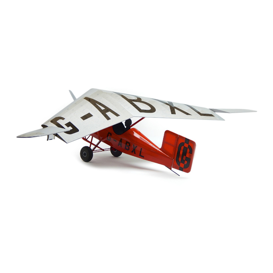
1930 ARCHAEOPTERYX
Sport-scale rendition of the Granger brothers unique 1930 homebuilt.
Wing Span: 40 inches | Wing Area: 220 square inches | Average Flying Weight: 9.5 ounces
Build Instructions - Version 1.24 (revised 10.01.2014)
Granger Build Instructions. © 2013 Stevens AeroModel all rights reserved.!
Page 1
Advertisement
Table of Contents

Related Manuals for Stevens AeroModel GRANGER 1930 ARCHAEOPTERYX


Summary of Contents for Stevens AeroModel GRANGER 1930 ARCHAEOPTERYX
- Page 1 Sport-scale rendition of the Granger brothers unique 1930 homebuilt. Wing Span: 40 inches | Wing Area: 220 square inches | Average Flying Weight: 9.5 ounces Build Instructions - Version 1.24 (revised 10.01.2014) Granger Build Instructions. © 2013 Stevens AeroModel all rights reserved.! Page 1...
- Page 2 Build Instructions WARRANTY Stevens AeroModel guarantees this kit to be free from defects in both material and workmanship at the date of purchase. This warranty does not cover any component parts damaged by use or modification. In no case shall Stevens AeroModel’s liability exceed the original cost of the purchased kit. Further, Stevens AeroModel reserves the right to change or modify this warranty without notice.
- Page 3 Granger family. It is now being restored to hopefully fly again. Our kit features the unique outlines and controls of the original airframe. Simple to build and a delight to fly, the Stevens AeroModel Granger Archaeopteryx will definitely turn heads at the flight line...besides it’s really fun to say.
- Page 4 Many of the suggested items listed below are available at your local hobby shop. For your convenience, Stevens AeroModel stocks all the power system components and most of the building supplies required to complete this kit. If you have difficulties sourcing any of these items locally, please visit our website, stevensaero.com to purchase the items necessary to complete your model.
- Page 5 Build Instructions Sheet Wood Inventory (1 of 2) Granger Build Instructions. © 2013 Stevens AeroModel all rights reserved.! Page 5...
- Page 6 Build Instructions Sheet Wood Inventory (2 of 2) Granger Build Instructions. © 2013 Stevens AeroModel all rights reserved.! Page 6...
- Page 7 Build Instructions General Assembly Instructions Thank you for purchasing the sport-scale Granger Archaeopteryx from Stevens AeroModel. This model has been developed and manufactured using state-of-the-art CAD/CAM systems. Our kits feature a unique interlocking construction process, that when compared to traditional building methods, saves countless hours of measuring, cutting, sanding, and fitting.
- Page 8 F1 and F2. Fit the servo tray F8 (sheet 07/14, 1/16 in. ply) to the front of F7, and “tack glue” in place. □ Granger Build Instructions. © 2013 Stevens AeroModel all rights reserved.! Page 8...
- Page 9 F3. Do not apply glue on the front. Tack Glue Step 3 Bottom View Step 7 Bottom View Tack Dry Fit Glue Bottom View Step 4 Step 8 Granger Build Instructions. © 2013 Stevens AeroModel all rights reserved.! Page 9...
- Page 10 Square the assembly on a flat surface, and “final bond” the rear portion of the fuselage, from F7 back, with thin CA. Granger Build Instructions. © 2013 Stevens AeroModel all rights reserved.! Page 10...
- Page 11 Build Instructions Tack glue Step 13 Tack Front Step 9 Step 10 Step 14 Bond This Step 15 Section Only Step 11 Step 12 Step 16 Granger Build Instructions. © 2013 Stevens AeroModel all rights reserved.! Page 11...
- Page 12 F18. Ensure that the strut fitting hole is not blocked, and that there is a 1/16 in. gap between the bottom edge of F21 and the bottom edge of the fuselage side. Bond with CA. Granger Build Instructions. © 2013 Stevens AeroModel all rights reserved.! Page 12...
- Page 13 Step 17 Cont. Step 21 Strut Fitting Flush Hole Step 22 Flush Strut 1/16 in. Fitting Step 18 Hole Step 19 Step 23 Strut Fitting 1/16 in. Hole Granger Build Instructions. © 2013 Stevens AeroModel all rights reserved.! Page 13...
- Page 14 F1. Bond the motor mount assembly together, and to F1, by building up a small filet of medium CA along all seams. Granger Build Instructions. © 2013 Stevens AeroModel all rights reserved.! Page 14...
-
Page 15: Table Of Contents
Build Instructions Step 24 Step 28 Step 25 Step 29 Neo-Magnet Rear View Step 26 Step 30 Tabs Rear View Step 27 Step 31 Font of Granger Build Instructions. © 2013 Stevens AeroModel all rights reserved.! Page 15... - Page 16 Fit F35 to the top of the fuselage - moist side out - covering the motor mount, and extending to the rear strut pocket. Hold in place with low-tack masking tape until dry. Granger Build Instructions. © 2013 Stevens AeroModel all rights reserved.! Page 16...
- Page 17 Step 36 Rear View Step 33 Rear View Step 37 Bond Bond Rear View Step 34 Rear View Step 38 F35a F35b Step 35 Rear View Step 39 Granger Build Instructions. © 2013 Stevens AeroModel all rights reserved.! Page 17...
-
Page 18: Step
When F40 is completely dry, remove the tape and bond the F40 assembly to F36, F37, the fuselage sides, and the rear tips of the forward sheeting F35. Granger Build Instructions. © 2013 Stevens AeroModel all rights reserved.! Page 18... -
Page 19: Step
Build Instructions Step 40 Step 44 Step 41 Step 45 F40a F40b F40c Step 42 Step 46 Step 43 Step 47 Granger Build Instructions. © 2013 Stevens AeroModel all rights reserved.! Page 19... -
Page 20: Step
DO NOT use thin CA to do this, as it will wick through the wood and bond the center portion to the motor mount. Granger Build Instructions. © 2013 Stevens AeroModel all rights reserved.! Page 20... - Page 21 Build Instructions Step 52 Step 48 Step 49 Flat Step 53 Step 50 Flat Step 53 Cont. Tack Tack Step 51 Step 54 Granger Build Instructions. © 2013 Stevens AeroModel all rights reserved.! Page 21...
-
Page 22: Step
The rear of the stringer will end just above and behind the pushrod exit hole at the rear of the fuselage. Ensure that the stringer is fully seated, then bond with CA. Granger Build Instructions. © 2013 Stevens AeroModel all rights reserved.! Page 22... - Page 23 Build Instructions Align Step 55 Step 58 Step 56 Step 59 Step 59 Cont. Align Step 56 Cont. Step 60 Align Step 57 Granger Build Instructions. © 2013 Stevens AeroModel all rights reserved.! Page 23...
-
Page 24: Step
CA where the housing passes through formers F7 and F13, and on the inside of the fuselage at the exit slot. Granger Build Instructions. © 2013 Stevens AeroModel all rights reserved.! Page 24... - Page 25 Step 62 Cont. Pushrod Exit Hole Step 61 Step 63 Bottom View Pushrod Step 61 Cont. Step 63 Cont. Exit Hole Step 62 Step 63 Cont. Bottom View Granger Build Instructions. © 2013 Stevens AeroModel all rights reserved.! Page 25...
- Page 26 N1 by wicking CA between all the mating surfaces. Position N4 (sheet 03/14, 3/16 in. balsa) over N3. Align the inner edges with the rest of the □ assembly. Bond with CA. Granger Build Instructions. © 2013 Stevens AeroModel all rights reserved.! Page 26...
-
Page 27: Tack Glue Step
Tack Glue Step 64 Flush Tack Glue Tack Step 68 Step 65 Step 69 Neo- Bond Magnets Bond Bond Bond Flush Bond Bond Step 66 Bottom View Step 70 Granger Build Instructions. © 2013 Stevens AeroModel all rights reserved.! Page 27... - Page 28 Press a neo-magnet into the hole in H5, oriented so that it attracts the magnet in the rear of the radio compartment. When you are satisfied that the magnet is correctly oriented, bond it to the hatch assembly. Granger Build Instructions. © 2013 Stevens AeroModel all rights reserved.! Page 28...
- Page 29 Build Instructions thru Step 71 Step 74 Step 75 Step 72 Step 72 Cont. Step 76 Step 73 Step 77 Neo-Magnet Granger Build Instructions. © 2013 Stevens AeroModel all rights reserved.! Page 29...
- Page 30 Fit to rear spar W3’s (sheet 11/14, 3/32 in. balsa) together, at a slight angle as shown. Do □ not bond. Fit the rear spar W3 to the rear of W1, and “tack glue” to each other and W1 with medium □ Granger Build Instructions. © 2013 Stevens AeroModel all rights reserved.! Page 30...
- Page 31 1/4 in. Step 78 Step 82 Step 79 Tack Step 83 Step 80 Step 84 Step 81 Top View Tack Glue 45 deg. Left Side Step 85 Right Side Granger Build Instructions. © 2013 Stevens AeroModel all rights reserved.! Page 31...
-
Page 32: Step
Fit and “tack glue” part W8 (sheet 11/14, 3/32 in. balsa) under the leading edges of ribs W5 □ and W6. Fit and bond leading edge web W9 to W8, and ribs W5, W6, and W7 on the left half of the □ wing. Granger Build Instructions. © 2013 Stevens AeroModel all rights reserved.! Page 32... -
Page 33: Step
Build Instructions Step 86 Step 89 Tack Glue Step 86 Cont. Step 90 Tack Glue Step 87 Step 91 Step 88 Step 91 Cont. Granger Build Instructions. © 2013 Stevens AeroModel all rights reserved.! Page 33... -
Page 34: Step
Fit rib W12 (sheet 09/14, 1/16 in. balsa) to the set of notches immediately outside rib W6. Fit rib W13 (sheet 09/14, 1/16 in. balsa) to the next set of notches out from rib W12. □ □ Granger Build Instructions. © 2013 Stevens AeroModel all rights reserved.! Page 34... -
Page 35: Step
Build Instructions Step 92 Step 95 Step 93 Step 96 Step 94 Step 97 Step 94 Cont. Step 98 Granger Build Instructions. © 2013 Stevens AeroModel all rights reserved.! Page 35... -
Page 36: Step
106. Fit and “tack glue” rib W22 (sheet 14/14, 1/32 in. ply) to the tips of, and flush up against the □ □ steps of the spars and the leading and trailing edges. Granger Build Instructions. © 2013 Stevens AeroModel all rights reserved.! Page 36... -
Page 37: Step
Build Instructions Step 99 Step 103 Step 100 Step 104 Step 101 Step 105 Step 102 Step 106 Granger Build Instructions. © 2013 Stevens AeroModel all rights reserved.! Page 37... -
Page 38: Step
114. Trim the outboard end of the leading edge flush with the outer face of rib W25. Set the □ □ remaining piece aside to be used for the elevons in a later step. Granger Build Instructions. © 2013 Stevens AeroModel all rights reserved.! Page 38... -
Page 39: Step
Build Instructions Step 107 Step 111 Step 108 1/4 in. sq. Leading Edge Stock Step 112 Step 109 Center Step 113 Step 110 Step 114 Trim Granger Build Instructions. © 2013 Stevens AeroModel all rights reserved.! Page 39... -
Page 40: Step
121. Cut the length of 1/8 in. diameter brass tube supplied in your kit into two pieces 1 5/8 in. □ □ long. Lay one length aside to be used for the other wing panel. Granger Build Instructions. © 2013 Stevens AeroModel all rights reserved.! Page 40... -
Page 41: Step
Bottom View Step 116 Step 120 Round Trim Step 120 Cont. Center Round 1/8 in. sq. Stock Step 117 Step 118 Step 121 Trim 1/8 in. Dia. Brass Tube Granger Build Instructions. © 2013 Stevens AeroModel all rights reserved.! Page 41... -
Page 42: Step
E6 is properly seated against the steps in the spar and leading/trailing edges. “Tack glue” E6 to the spar and the leading/trailing edges, applying the glue to the inside of the rib only. Granger Build Instructions. © 2013 Stevens AeroModel all rights reserved.! Page 42... -
Page 43: Step
Build Instructions Step 122 Step 125 Step 123 Step 126 Step 123 Cont. Step 127 Step 124 Step 128 Granger Build Instructions. © 2013 Stevens AeroModel all rights reserved.! Page 43... - Page 44 E11 and E12. This channel must remain clear to allow the installation of the elevon pivot tube in a later step. Granger Build Instructions. © 2013 Stevens AeroModel all rights reserved.! Page 44...
- Page 45 Build Instructions Step 129 Step 133 1/4 in. sq. Leading Edge Stock Step 130 Step 134 Trim Step 131 Step 135 No Glue! Step 132 Step 136 No Glue! Granger Build Instructions. © 2013 Stevens AeroModel all rights reserved.! Page 45...
- Page 46 143. Remove the brass tube, and “final bond” E16 to the elevon assembly. Ensure than no glue □ □ enters the hole in the root ribs. Granger Build Instructions. © 2013 Stevens AeroModel all rights reserved.! Page 46...
-
Page 47: Step
Build Instructions Step 137 Step 141 No Glue! Step 138 Step 142 Tack Tack Step 139 Step 142 Cont. Step 143 Bond E16b E16a No Glue! Bond Step 140 Granger Build Instructions. © 2013 Stevens AeroModel all rights reserved.! Page 47... - Page 48 147. Remove the covering over the small holes in the strut anchor plates (4). □ 148. Remove the covering over the wing center section access holes, and the slots for the wing □ mounting tabs. Granger Build Instructions. © 2013 Stevens AeroModel all rights reserved.! Page 48...
- Page 49 Step 147 Edge to Match Contour of Spars Step 144 Cont. Step 144 Cont. Step 148 Center Section Round Step 145 Step 148 Cont. Center Section Bottom View Granger Build Instructions. © 2013 Stevens AeroModel all rights reserved.! Page 49...
- Page 50 153. Clip one arm from the long, 3 hole control horn supplied with the HS-35HD servos. Electronically center the servo, then mount the control horn perpendicular to the body of the servo, as shown. Granger Build Instructions. © 2013 Stevens AeroModel all rights reserved.! Page 50...
- Page 51 Build Instructions Step 149 Step 151 Step 149 Cont. Step 151 Cont. Bond Bond Bond Step 150 Step 152 Step 150 Cont. Step 153 Bond Granger Build Instructions. © 2013 Stevens AeroModel all rights reserved.! Page 51...
- Page 52 157. Connect an 8 in. servo extension to each 6 in. servo extension. □ 158. Feed the extension through the holes in the wing ribs, and down through the exit holes in □ the wing center section. Granger Build Instructions. © 2013 Stevens AeroModel all rights reserved.! Page 52...
- Page 53 Build Instructions Step 154 Step 156 Step 154 Cont. Step 156 Cont. Step 154 Cont. Step 157 Trailing Edge 90 deg. Step 155 Step 158 Granger Build Instructions. © 2013 Stevens AeroModel all rights reserved.! Page 53...
- Page 54 Orient the tube so that the slot faces toward the trailing edge. Bond the tube to the elevon by wicking CA where the tube enters the elevon. □ 163. Side three #4 nylon washers onto the axle tube. Granger Build Instructions. © 2013 Stevens AeroModel all rights reserved.! Page 54...
- Page 55 Step 158 Cont. Step 161 Cont. 1/8 in. Step 162 Step 159 Step 160 Step 162 Cont. 2-3/4 in. Slot Faces Aft 3 Washers Step 161 Step 163 Granger Build Instructions. © 2013 Stevens AeroModel all rights reserved.! Page 55...
- Page 56 172. Cut the 1/8 in. dowel supplied in the kit into two equal lengths. Build the scale motor cylinders over the dowels. Begin by sliding M1 (sheet 05/14, 3/16 in. balsa) over the dowel. Granger Build Instructions. © 2013 Stevens AeroModel all rights reserved.! Page 56...
- Page 57 Build Instructions Step 164 Step 168 Step 165 Step 169 Angle Gauge Step 166 Step 170 Elevon bottom Step 167 Step 172 1/8 in. Dowel Granger Build Instructions. © 2013 Stevens AeroModel all rights reserved.! Page 57...
- Page 58 179. Press one of the black dished washers onto each leg of the landing gear wire, with the flat □ side facing out. Granger Build Instructions. © 2013 Stevens AeroModel all rights reserved.! Page 58...
- Page 59 Build Instructions Step 173 5/8 in. Step 177 Step 174 Step 178 Step 175 Step 178 Cont. Step 176 Step 179 1/16 in. Wire Dished Washer, Flat Side Out Granger Build Instructions. © 2013 Stevens AeroModel all rights reserved.! Page 59...
- Page 60 Ensure that all four legs of the struts are firmly seated in the fuselage, then bond the carbon rods to the struts with medium CA. Do not bond the struts to the fuselage. Granger Build Instructions. © 2013 Stevens AeroModel all rights reserved.! Page 60...
- Page 61 Build Instructions Step 180 Step 183 Cont. Flush with Fuselage Dished Bottom Washer Step 184 Step 181 .070 Carbon Rod Step 182 Step 185 Step 183 Step 186 Granger Build Instructions. © 2013 Stevens AeroModel all rights reserved.! Page 61...
- Page 62 194. Assemble the rear struts from ply parts CS3 (sheet 07/14, 1/16 in. ply) and two CS4’s □ (sheet 06/14, 1/32 in. ply). Ensure that the angled leg of both CS4’s point in the same direction. Bond the assembly with CA. Granger Build Instructions. © 2013 Stevens AeroModel all rights reserved.! Page 62...
- Page 63 Build Instructions Step 191 Step 187 Step 188 Step 192 Step 193 Step 189 Step 190 Step 194 2-1/2 in. .070 Carbon Rod Granger Build Instructions. © 2013 Stevens AeroModel all rights reserved.! Page 63...
- Page 64 1/16 in. diameter. Clip off the remaining arms. Install the E/Z Connector supplied in the kit, then install the arm to the servo, oriented as shown. Granger Build Instructions. © 2013 Stevens AeroModel all rights reserved.! Page 64...
- Page 65 Build Instructions Step 195 Step 197 Tack Glue Step 195 Cont. Step 198 Step 196 Step 199 Right Side of Rudder Step 196 Cont. Step 200 Granger Build Instructions. © 2013 Stevens AeroModel all rights reserved.! Page 65...
- Page 66 208. Mount the four armed motor mount to the back of the motor. Use CA, glue a #4 nylon □ washers to the back of each arm on the left side of the motor, as viewed from the rear. Granger Build Instructions. © 2013 Stevens AeroModel all rights reserved.! Page 66...
- Page 67 Step 205 Heat Shrink Tube Right Side 3/4 in. Step 202 1/32 in. Wire Step 206 Step 203 Step 207 1 in. Left Side Step 204 Step 208 Granger Build Instructions. © 2013 Stevens AeroModel all rights reserved.! Page 67...
- Page 68 Scrape the channel out just enough so that the wire will lie fully within the channel. Do not remove more material than necessary, as this may weaken the strut. Granger Build Instructions. © 2013 Stevens AeroModel all rights reserved.! Page 68...
- Page 69 Mounting Tabs Step 213 Step 210 Step 214 Cont. Rubber Retainer Step 211 Step 215 .045 Wire Step 212 Check Depth 1/4 in. .075 Wire Step 215 Cont. Granger Build Instructions. © 2013 Stevens AeroModel all rights reserved.! Page 69...
- Page 70 220. Mount the propellor [GW/EP7035] to the propellor adaptor on the motor. Congratulations! Your Stevens AeroModel 1930 Granger Archaeopteryx is finished. Proceed to the Set Up and Preflight sections to ready your model for it’s first flight. Granger Build Instructions. © 2013 Stevens AeroModel all rights reserved.!
- Page 71 Build Instructions Step 216 Step 219 F1a F1b Step 217 Step 220 Step 218 Complete! Step 218 Granger Build Instructions. © 2013 Stevens AeroModel all rights reserved.! Page 71...
- Page 72 When trimming the model do so first electronically on your radio, then use the Granger Build Instructions. © 2013 Stevens AeroModel all rights reserved.! Page 72...
- Page 73 Inspect Battery - Always use a freshly-charged battery. Never begin a flight with a partially-charged or damaged battery. Granger Build Instructions. © 2013 Stevens AeroModel all rights reserved.! Page 73...
- Page 74 Setup for Landing - Clearly announce your intentions to land. Make all landings into the wind, using rudder and elevator controls. Crosswind landings should be avoided until you are comfortable with the model’s in-flight behavior. Granger Build Instructions. © 2013 Stevens AeroModel all rights reserved.! Page 74...
- Page 75 Build Instructions Congratulations! You’ve completed your first flight(s) on your Stevens AeroModel Granger By now you’ll have noticed that the Granger is a very stable airplane. When built straight, and trimmed for level flight, the Granger readily return to wings level from any attitude. We’ve found the Granger to capture the imagination of prospective pilots both young and old.
Need help?
Do you have a question about the GRANGER 1930 ARCHAEOPTERYX and is the answer not in the manual?
Questions and answers