Advertisement
Quick Links
Build Instructions
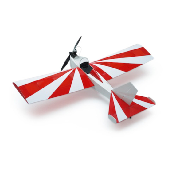
microMAX
103
Wayne Ison's part 103 legal home built.
Wing Span: 18.5 inches | Wing Area: 65 square inches | Average Flying Weight: 1.5 ounces
Build Instructions - Version 1.0 (revised 05.13.2014)
microMAX 103 Build Instructions. © 2013 Stevens AeroModel all rights reserved.!
Page 1
Advertisement

Related Manuals for Stevens AeroModel microMAX 103


Summary of Contents for Stevens AeroModel microMAX 103
- Page 1 Wayne Ison’s part 103 legal home built. Wing Span: 18.5 inches | Wing Area: 65 square inches | Average Flying Weight: 1.5 ounces Build Instructions - Version 1.0 (revised 05.13.2014) microMAX 103 Build Instructions. © 2013 Stevens AeroModel all rights reserved.! Page 1...
- Page 2 Build Instructions WARRANTY Stevens AeroModel guarantees this kit to be free from defects in both material and workmanship at the date of purchase. This warranty does not cover any component parts damaged by use or modification. In no case shall Stevens AeroModel’s liability exceed the original cost of the purchased kit. Further, Stevens AeroModel reserves the right to change or modify this warranty without notice.
- Page 3 1 - 2 in length of 1/16 in. diameter Heat Shrink Tube 1 - Nylon Receiver Clip 1 - 1/16 in. x 1-3/4 in. Aluminum Tube 1 - Pair Plastic Wheels [SIGSH540] microMAX 103 Build Instructions. © 2013 Stevens AeroModel all rights reserved.! Page 3...
- Page 4 ☐ DEFT clear lacquer based sealant (available at most hardware stores). ☐ Design Master Color Tool lacquer based spray paint (available at most art supply stores). microMAX 103 Build Instructions. © 2013 Stevens AeroModel all rights reserved.! Page 4...
- Page 5 Build Instructions Sheet Wood Inventory (1 of 1) microMAX 103 Build Instructions. © 2013 Stevens AeroModel all rights reserved.! Page 5...
- Page 6 Build Instructions Builders Notes microMAX 103 Build Instructions. © 2013 Stevens AeroModel all rights reserved.! Page 6...
- Page 7 Build Instructions General Assembly Instructions Thank you, for purchasing this Stevens microMAX 103. This product has been developed and manufactured using state of the art CAD/CAM systems and features a unique interlocking construction process that, when compared to traditional methods found in other model aircraft kits, save countless hours of measuring, cutting, sanding, and fitting.
- Page 8 These notches and slots are oversized to accommodate all three parts of the landing gear pocket. Part F8 must occupy the forward portion of these openings. Do not bond. microMAX 103 Build Instructions. © 2013 Stevens AeroModel all rights reserved.! Page 8...
- Page 9 Tabs Protrude Slightly Step 1 Step 2 Step 5 F6 (behind F7) right Step 3 Step 6 Bottom View F6 (behind F7) Slots Step 4 Step 7 microMAX 103 Build Instructions. © 2013 Stevens AeroModel all rights reserved.! Page 9...
- Page 10 Now, snap off the four mounting spikes on the tabs of the motor [PKZ3624], and sand the □ tabs smooth. microMAX 103 Build Instructions. © 2013 Stevens AeroModel all rights reserved.! Page 10...
-
Page 11: Bottom View
Step 7 Cont. Step 11 Bottom View Step 8 Step 12 Bottom View Step 9 Step 13 bottom Step 10 Step 14 F5 (behind F11) Sand Smooth left microMAX 103 Build Instructions. © 2013 Stevens AeroModel all rights reserved.! Page 11... - Page 12 Fit the fuselage rear decking F18 to the tabs along the top of former F4, resting on the fuselage sides just behind F4. Tack glue F18 to F4, and the first 1/4 in. of the fuselage sides immediately behind F4. microMAX 103 Build Instructions. © 2013 Stevens AeroModel all rights reserved.! Page 12...
- Page 13 Step 15 Cont. Step 18 Bottom View Step 16 Step 19 left Hole Bottom View Step 16 Cont. No Glue! Bond Radio No Glue! Compartment Top View Step 20 microMAX 103 Build Instructions. © 2013 Stevens AeroModel all rights reserved.! Page 13...
- Page 14 Tip: part F23 and F24 feature two 1/8 in. alignment holes to assist with location of the part. Use a scrap 1/8 in. dowel or drill bit(s) as alignment jigs through the holes int the parts. microMAX 103 Build Instructions. © 2013 Stevens AeroModel all rights reserved.! Page 14...
- Page 15 Bottom View Bottom View Step 22 Step 27 Bottom View Bottom View Step 23 Step 28 F20a F20b Bottom View Step 24 Step 29 Bottom View Bottom View microMAX 103 Build Instructions. © 2013 Stevens AeroModel all rights reserved.! Page 15...
- Page 16 Align M2 and M3 so that their sides are flush with each other. Ensure that M1 is fully seated in the slots, and bond with tiny drops of thin CA. microMAX 103 Build Instructions. © 2013 Stevens AeroModel all rights reserved.! Page 16...
- Page 17 Sand F25b F25a Sharp Edges Step 31 Step 34 Thin CA Step 32 Step 35 Repeat for: M3, M4, and M5 Step 33 Step 36 Sharp Edges microMAX 103 Build Instructions. © 2013 Stevens AeroModel all rights reserved.! Page 17...
- Page 18 Set the completed head rest aside until the “Final Assembly” steps outlined in this manual. microMAX 103 Build Instructions. © 2013 Stevens AeroModel all rights reserved.! Page 18...
- Page 19 Build Instructions Step 37 Step 41 Step 38 Step 42 1/8 in. extension Step 39 Step 43 or trim flush Top View Step 40 Step 44 Front Bottom microMAX 103 Build Instructions. © 2013 Stevens AeroModel all rights reserved.! Page 19...
-
Page 20: Wing Assembly
Ensure that the spar fits into the recesses in each rib. Bond the ribs to the wing panel with thin CA. microMAX 103 Build Instructions. © 2013 Stevens AeroModel all rights reserved.! Page 20... - Page 21 Control Horn Slots Step 46 Step 50 45 Deg. End View Step 47 Step 51 Rudder Horn Slot Step 48 Weight 45 Deg. Top View Step 52 microMAX 103 Build Instructions. © 2013 Stevens AeroModel all rights reserved.! Page 21...
- Page 22 Snap off the stand-off tabs on ribs W4, W5, and W6, and sand the bottom of the ribs □ □ smooth. microMAX 103 Build Instructions. © 2013 Stevens AeroModel all rights reserved.! Page 22...
- Page 23 Step 56 Sight, trim, sand. No Gaps REMOVE Step 54 Cont. Step 56 Cont. No Gaps Step 55 Step 57 Remove Root standoffs. 1/4 in. Level Rear View microMAX 103 Build Instructions. © 2013 Stevens AeroModel all rights reserved.! Page 23...
-
Page 24: Final Assembly
Follow the push-rod instructions given on the plan set to produce the requisite “snake bend” □ at one end of each piece of the provided 0.015 in. wire. microMAX 103 Build Instructions. © 2013 Stevens AeroModel all rights reserved.! Page 24... - Page 25 Build Instructions Step 58 Step 60 Cont. Leave Bottom Uncovered Step 58 Cont. Step 61 Sand Step 61 Cont. Bond Step 59 Step 62 Step 60 microMAX 103 Build Instructions. © 2013 Stevens AeroModel all rights reserved.! Page 25...
- Page 26 Attach a 3 in. extension to the battery lead [SAUMEXT/3]. Feed the battery lead down through the opening in F2/F3, and into the battery compartment □ at the nose of the model. microMAX 103 Build Instructions. © 2013 Stevens AeroModel all rights reserved.! Page 26...
- Page 27 Step 66 Right right Inner Left left 3 in. extension [SAUMEXT/3] Step 64 Cont. Step 67 right side fuselage top Step 64 Cont. left side Step 67 Cont. microMAX 103 Build Instructions. © 2013 Stevens AeroModel all rights reserved.! Page 27...
- Page 28 When you are satisfied that the vertical stabilizer is on straight, run a tiny bead of medium CA along the seam between the stabilizer surfaces on both sides. microMAX 103 Build Instructions. © 2013 Stevens AeroModel all rights reserved.! Page 28...
- Page 29 Step 73 rudder bevelled side down Step 70 Step 74 Step 75 Step 71 bevelled perpendicular edge (90 degrees) lower left side of Bottom View elevator microMAX 103 Build Instructions. © 2013 Stevens AeroModel all rights reserved.! Page 29...
- Page 30 Mount the plastic wheels supplied in your kit, and bend the axle wire up 90 degrees to □ retain the wheels. Now, trim off the excess wire about 1/8 in. from the retaining bend. microMAX 103 Build Instructions. © 2013 Stevens AeroModel all rights reserved.! Page 30...
- Page 31 Build Instructions Step 76 Step 80 Step 81 Step 77 Step 78 Step 82 bend 1/32 wire to match plan Step 79 Step 83 bend to retain wheel microMAX 103 Build Instructions. © 2013 Stevens AeroModel all rights reserved.! Page 31...
- Page 32 Grasp the prop shaft with a pair of needle nose pliers, and thread the propellor [ELF9051] □ onto the shaft. Congratulations! Your microMAX 103 is now complete! Proceed to the Setup and Pre-Flight sections to prepare your model for it’s first flight.
- Page 33 Build Instructions Step 84 Step 88 Bottom View Step 85 Bottom View Bond Tack Glue Bond Step 89 Step 86 Bond Bond Step 90 Step 87 Step 91 microMAX 103 Build Instructions. © 2013 Stevens AeroModel all rights reserved.! Page 33...
- Page 34 Sure it’s a little bitty flexible plastic prop but it’s still fun to yell “Clear Prop” Before applying power to the model... and an excellent habit to form. microMAX 103 Build Instructions. © 2013 Stevens AeroModel all rights reserved.! Page 34...
- Page 35 The most microMAX 103 Build Instructions. © 2013 Stevens AeroModel all rights reserved.! Page 35...
Need help?
Do you have a question about the microMAX 103 and is the answer not in the manual?
Questions and answers