
Related Manuals for Stevens AeroModel BuzzBomb 100


Summary of Contents for Stevens AeroModel BuzzBomb 100
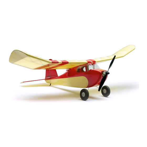
- Page 1 Build Instructions BuzzBomb 100 Toon Buzzard Bombshell Length 16 inches | Span 21 inches | Area: 100 inches | Flying Weight 1.8 oz. Version 02/21/2012 © 2012 Stevens AeroModel all rights reserved.! Page 1 of 12...
-
Page 2: Build Instructions
Build Instructions WARRANTY Stevens AeroModel guarantees this kit to be free from defects in both material and workmanship at the date of purchase. This warranty does not cover any component parts damaged by use or modification. In no case shall Stevens AeroModel’s liability exceed the original cost of the purchased kit. Further, Stevens AeroModel reserves the right to change or modify this warranty without notice. -
Page 3: Kit Contents
☐ Masking Tape (Low tack painters tape) ☐ Small Needle Nose Pliers ☐ 1/2 in. wide clear or hinge tape [DUB916] ☐ Soldering Iron ☐ AeroLITE Film (3 Patch Packs or 1 Roll) © 2012 Stevens AeroModel all rights reserved.! Page 3 of 12... - Page 4 (use no glue) the parts together first. It’s advised to work 1-2 steps ahead in the instructions using this dry-fit technique which allows ample opportunity to inspect the fit and location of assembled © 2012 Stevens AeroModel all rights reserved.! Page 4 of 12...
- Page 5 4. Fit and tack glue battery tray F3 perpendicular to former F2 as illustrated on the plan. 5. Fit and tack glue former F4 perpendicular to the rear of the central crutch F1. Observe the © 2012 Stevens AeroModel all rights reserved.! Page 5 of 12...
- Page 6 F18 supports to the spine, former F4 and each other with thin CA. 21. Fit and bond forward wing retention dowel mount F19 to wing saddle F17 and fuselage sides. © 2012 Stevens AeroModel all rights reserved.! Page 6 of 12...
- Page 7 Rudder following the “Stabilizer and Rudder Tape Hinge Diagram” and sanding 40. Fit and tack glue sub-ribs W9 and W10 to W1 instructions given on the plan set. spar and W7/W8 leading edge. © 2012 Stevens AeroModel all rights reserved.! Page 7 of 12...
- Page 8 Tack glue to rounding leading edge to match the profile on retain. the fuselage plan sheet. Leaving the trailing edge square. 51. Fit sub-rib W24 to leading edge and spar. © 2012 Stevens AeroModel all rights reserved.! Page 8 of 12...
-
Page 9: Final Assembly
F17. 74. Open up slot on RIGHT side of rudder to receive one laser cut control horn. Fit and bond control horn as illustrated on plan. © 2012 Stevens AeroModel all rights reserved.! Page 9 of 12... - Page 10 Note: CA glue is perfectly acceptable to use here. Just remember that CA glue is semi permanent and motor replacement will be a challenge. White glue, hot glue, and silicone adhesives (caulk) are also acceptable. © 2012 Stevens AeroModel all rights reserved.! Page 10 of 12...
- Page 11 Get in the habit of always pre-flighting your models before each and every flight. © 2012 Stevens AeroModel all rights reserved.! Page 11 of 12...
- Page 12 We are committed to improving your build and flying experience and are constantly refining our processes, designs, and manuals to reflect customer feedback. You may correspond with Stevens AeroModel staff using any of the following methods: © 2012 Stevens AeroModel all rights reserved.! Page 12 of 12...
Need help?
Do you have a question about the BuzzBomb 100 and is the answer not in the manual?
Questions and answers