Table of Contents
Advertisement
Quick Links
Advertisement
Table of Contents

Related Manuals for Stevens AeroModel Hummingbird (100)


Summary of Contents for Stevens AeroModel Hummingbird (100)
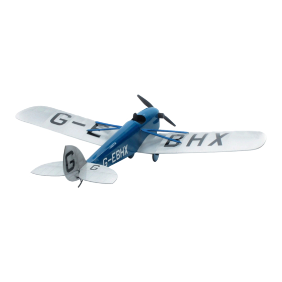
- Page 1 DH.53 Hummingbird (100) Build Instructions Revised 06/17/2011 Hummingbird (100) By Stevens AeroModel Length 17.5 inches | Span 27 inches | Area: 100 inches | Flying Weight 2.3 oz. Version 1.0 © 2011 Stevens AeroModel all rights reserved.! Page 1 of 11...
-
Page 2: Warranty
Revised 06/17/2011 WARRANTY Stevens AeroModel guarantees this kit to be free from defects in both material and workmanship at the date of purchase. This warranty does not cover any component parts damaged by use or modification. In no case shall Stevens AeroModel’s liability exceed the original cost of the purchased kit. Further, Stevens AeroModel reserves the right to change or modify this warranty without notice. -
Page 3: Kit Contents
☐ Sanding block with 400 and 600 grit paper ☐ Heat Gun and Covering Iron ☐ Small Needle Nose Pliers ☐ 1/2 in. wide clear tape ☐ Servo mounting tape ☐ Soldering Iron © 2011 Stevens AeroModel all rights reserved.! Page 3 of 11... - Page 4 (use no glue) the parts together first. It’s advised to work 1-2 steps ahead in the instructions using this dry-fit technique which allows ample opportunity to © 2011 Stevens AeroModel all rights reserved.! Page 4 of 11...
- Page 5 8. Fit wing mount assembly to fuselage side F3. Part F8 should be on top and the tabs on F7 23. Fit and bond formers F20 and F21 to central should point down. crutch F1. © 2011 Stevens AeroModel all rights reserved.! Page 5 of 11...
- Page 6 DO NOT bond motor mount at this time. the nose block as viewed from the top, and follow the contours on the plan for the side views. Sand the corners of F18 and F19 at © 2011 Stevens AeroModel all rights reserved.! Page 6 of 11...
- Page 7 Wing parts and bonding together parts W11, W12, and are designated with a “W” followed by a numeric. W13. Parts have been numbered so that the wing © 2011 Stevens AeroModel all rights reserved.! Page 7 of 11...
-
Page 8: Final Assembly
CA along the side of the tube, remaining wires. Alternately, when using the being careful not to fill the center of the tube larger 200 mAh battery [EFLB2001S25], the with glue. © 2011 Stevens AeroModel all rights reserved.! Page 8 of 11... - Page 9 Fit the vertical stabilizer pocket and bond with a small drop of thin CA. tabs through the slots in the horizontal stabilizer and into the slots in F19. Ensure © 2011 Stevens AeroModel all rights reserved.! Page 9 of 11...
- Page 10 If not, re-bend the wires at the wing until the top of Elevator Travel the strut is aligned correctly. +/- 10 degrees 30% expo © 2011 Stevens AeroModel all rights reserved.! Page 10 of 11...
- Page 11 ☐ Check wing attach points for damage and/ customer feedback. You may correspond with or wear. Inspect magnets and struts, Stevens AeroModel staff using any of the ensuring that they are installed correctly and following methods: in good condition to adequately retain wing. E-Mail - support@stevensaero.com...
Need help?
Do you have a question about the Hummingbird (100) and is the answer not in the manual?
Questions and answers