
Related Manuals for Stevens AeroModel G-480


Summary of Contents for Stevens AeroModel G-480
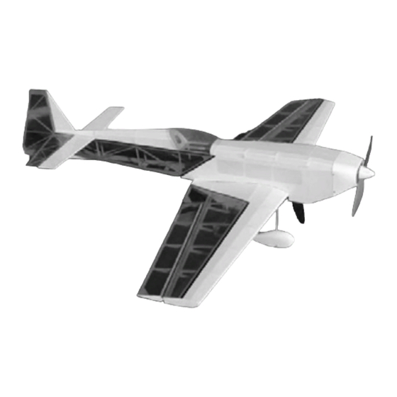
- Page 1 G-480 V1.11 Span 45” / Length 44” / Area 400 Sq.” / Weight 22-28oz © 2004 Stevens AeroModel. Page 1 of 33...
- Page 2 Similar to full-scale and giant scale models this high performance model requires careful throttle management. When tracking through a down-line it is mandatory to govern the use of throttle, slowing the models descent, to avoid over stressing the airframe. © 2004 Stevens AeroModel. Page 2 of 33...
- Page 3 This option eliminates the pull pull assembly for the elevator and allows for greater CG adjustment with heavier motor systems. Requires 12" Extension Optional © 2004 Stevens AeroModel. Page 3 of 33...
- Page 4 22A Burst. Other Items You Will Need: Thin CA (super glue) Five Minute Epoxy Wax Paper or Plastic Wrap Razor Blade(s) Fine Grit Sand Paper Rat-Tail File Clear Tape Balsa Wood Filler © 2004 Stevens AeroModel. Page 4 of 33...
- Page 5 GENERAL ASSEMBLY INSTRUCTIONS: Thank you, for purchasing this Stevens Aeromodel G-480 – Groove. This kit provides the builder and pilot a refreshing change of pace from heavy “ARF” style plywood box airframe construction and blends stick and tissue design methods of the past with state of the art CAD technology and precision interlocking laser cut parts;...
-
Page 6: Tail Feathers
Let’s assemble the major fuselage components. Assemble Fuselage sides and formers F6, F7, F14, FT1, FB1, FB2, FB3, and H1. Align parts with rolled plan sheet and wick CA into joints. F14A F14B © 2004 Stevens AeroModel. Page 10 of 33... - Page 7 Now Double check your parts fit and wick thin CA along inside fuselage joints along components assembled thus far. Work slowly and make strong joints. © 2004 Stevens AeroModel. Page 11 of 33...
- Page 8 CA or one application of thick CA allowing time to cure in-between applications) Fit Servo rail / fuselage doubler part SR1 inside fuselage to double FT1 servo pocket. Friction Fit former F5A to 1/8” fuselage gussets F5B to create former F5. © 2004 Stevens AeroModel. Page 12 of 33...
- Page 9 11. Support fuselage assembly upright on a flat surface and tack glue F5, FB3, and F8 into position. Verify that the fuselage tail-section is square to the building board and run thin CA along all inside surfaces. Work slowly and make strong joints. © 2004 Stevens AeroModel. Page 13 of 33...
- Page 10 F8. Run thin CA along inside surfaces. 14. Key FT4 into position secure with thin CA. 15. Key F14 and F15 turtle deck spine into position. Part F15 spans FT4, F7, F6, and F14. Secure parts with thin © 2004 Stevens AeroModel. Page 14 of 33...
- Page 11 Once satisfied with fit, glue the assembly together by running thin CA along all inside surfaces. (Note the servo tray included with the beta kit). Stringers are slightly oversized sand excess stringer length flush with F11 and F13. © 2004 Stevens AeroModel. Page 15 of 33...
- Page 12 NEVER run a prop adapter that is damaged or bent. (Ignoring any of these suggestions may lead to vibration that may damage the airframe, motor mount, and your electronics) Disable your prop brake on the ESC (out runner motors and prop brakes are not a good combination) © 2004 Stevens AeroModel. Page 16 of 33...
- Page 13 Be sure to sand a slight bevel in the aft end of the fuselage at F8 extending aft to make for a gentle transition to the Rudder surface and prevent control horn binding. © 2004 Stevens AeroModel. Page 17 of 33...
- Page 14 At this point it is a very good idea to lightly sand both sides of the wing ribs and spar. It is also a good time to consider lightly sanding the burn marks from the edges of the ribs – be very gentle as the assembly is quite delicate at this point. © 2004 Stevens AeroModel. Page 18 of 33...
- Page 15 Nest the wing center brace part W1 in-between ribs R1. Flip the wing over on a flat surface (to rest on the riser jigs built into the ribs) and tack glue W1 into position. © 2004 Stevens AeroModel. Page 19 of 33...
- Page 16 1/8” holes in the wing center section trailing edge components. Tack glue parts W4 and W5 (well away from the 1/8” dowels). Remove the centering dowels and wick thin CA between surfaces to laminate the trailing edge components together. © 2004 Stevens AeroModel. Page 20 of 33...
- Page 17 12. Assemble the landing gear block: Locate parts LG1 – LG6 and friction fit together as indicated in the photo below. 13. Key the center landing gear block to the wing between ribs R1 and the main spar. Align flush with R1 and the main spar. Tack glue into position. © 2004 Stevens AeroModel. Page 21 of 33...
- Page 18 – this will require rocking the wing to one side at a time as the bottom of the wing has a bit of taper built into it. Flip the wing back over – weigh it down – and run thin CA along the spar to rib joints. © 2004 Stevens AeroModel. Page 22 of 33...
- Page 19 – also LE4 is designed to fit in one direction – pay close attention to the notching. 19. Stand wing up along its leading edge supported over your flat work surface. Hold LE3 firmly against LE 4 and wick thin CA along joints between LE3 and LE4 surfaces. © 2004 Stevens AeroModel. Page 23 of 33...
- Page 20 CA. If for some reason your wing does not come out straight and true – you may simply leave the wing inverted on your flat work surface, weighted down, mist liberally with glass cleaner solution, and allow to completely dry. © 2004 Stevens AeroModel. Page 24 of 33...
- Page 21 25. Sand leading edge – round to match shape of airfoil. 26. Test fit the wing to the Fuselage and inspect for proper fit. Sand trailing edge of wing to fit fuselage wing saddle. © 2004 Stevens AeroModel. Page 25 of 33...
- Page 22 Test fit aileron rib and trailing edge assembly to parts A5/A6 leading edge – tack glue in place – then lay flay on building board and finalize the glue joints. © 2004 Stevens AeroModel. Page 26 of 33...
- Page 23 Next run thin CA into spade by allowing it to wick in along the gear legs where they enter the spade. Sand exterior of spade to fit into gear block (in wing). © 2004 Stevens AeroModel. Page 27 of 33...
-
Page 24: Wheel Pants
1/16” ply part WP3A Lightly sand and install into pocket created by WP4 and WP3. Laminate Stack A to Stack B - THE PLY INSERT (STACK B) MUST FACE INSIDE THE WHEEL PANT. Next laminate part WP5 to WP4 on the exterior of each stack. © 2004 Stevens AeroModel. Page 28 of 33... -
Page 25: Tail Wheel
Using the plan sheet as a guide cut and bend 1/32” wire and aluminum bearing to shape/size. Using provided length of Kevlar thread lash the aluminum bearing to tail wheel assembly “A”. © 2004 Stevens AeroModel. Page 29 of 33... - Page 26 Hint: Painting the Cowl. Lay up multiple thin coats of paint, allowing ample time to dry, on the cowl to avoid melting of the part by the aggressive solvents in your paint. © 2004 Stevens AeroModel. Page 30 of 33...
-
Page 27: Final Assembly
Apply adhesive back Velcro (not included) to battery tray. Mount battery with Velcro to BT1 battery tray. The supplied Velcro tie wrap is intended to augment the adhesive back mounting system – not substitute it. Mount receiver with Double Sided Tape or Velcro to F6 receiver tray. © 2004 Stevens AeroModel. Page 31 of 33... -
Page 28: First Flight
Slowly advance throttle – within a few feet you will be airborne. The G-Ride slows down nicely for landings; however, make your first landings with slight power-on until you are familiar with the aircraft’s stall. © 2004 Stevens AeroModel. Page 32 of 33... - Page 29 THIS PAGE HAS BEEN PROVIDED TO SCHEME A COLOR SCHEME: M P J 45DEG © 2004 Stevens AeroModel. Page 33 of 33...
Need help?
Do you have a question about the G-480 and is the answer not in the manual?
Questions and answers