
Related Manuals for Stevens AeroModel EDGE 540


Summary of Contents for Stevens AeroModel EDGE 540
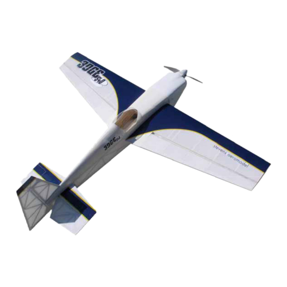
- Page 1 R1.0 Span 50” / Length 45” / Area 440 Sq.” / Weight 26-30oz © 2005 Stevens AeroModel. Page 1 of 46...
-
Page 2: Warranty
Further, Stevens AeroModel reserves the right to change or modify this warranty without notice. In that Stevens AeroModel has no control over the final assembly or material used for final assembly, no liability shall be assumed nor accepted for any damage resulting from the use by the user of the final user-assembled product. - Page 3 Other Items You Will Need: Thin and Medium CA (super glue) Five Minute Epoxy Wax Paper or Plastic Wrap Sharp Hobby Knife Fine Grit Sand Paper Rat-Tail File Masking Tape Balsa Wood Filler © 2005 Stevens AeroModel. Page 3 of 46...
- Page 4 GENERAL ASSEMBLY INSTRUCTIONS: Thank you, for purchasing this Stevens AeroModel Edge 540. This kit provides the builder and pilot a refreshing change of pace from heavy “ARF” style plywood box airframe construction and blends stick and tissue design methods of the past with state of the art CAD technology and precision interlocking laser cut parts;...
-
Page 5: Tail Feathers
Assemble the major fuselage components; fuselage sides and formers F3, F4, F5, FB1, FB2, and FB10. Align parts with rolled plan sheet and wick CA into joints. LEAVE OPEN COOLING AIR EXIT POINT Optional wing retention using " Neo Magnet. © 2005 Stevens AeroModel. Page 10 of 46... - Page 6 Next, install FB5, FB6, and FB7 which forms the trailing edge of the battery access. Finish by installing FB8 and FB9. Reference photos below. © 2005 Stevens AeroModel. Page 11 of 46...
- Page 7 FB7. Now, install the second magnet, within the battery cover assembly, with the marked side DOWN. The photos below reference the magnet install and completed fuselage bottom plate assembly. © 2005 Stevens AeroModel. Page 12 of 46...
- Page 8 CA along the outside of the nut – do not allow glue to come in contact with the internal threaded portion of the blind nuts! Assemble the battery tray BT1 to the slots on the back side of the firewall as indicated below. © 2005 Stevens AeroModel. Page 13 of 46...
- Page 9 WS1) and key within the fuselage to the top of BT1. Next, locate the 1/32” ply part BT3 and key within the fuselage to the top of BT2. Reference the plan sheet for specific location. © 2005 Stevens AeroModel. Page 14 of 46...
- Page 10 12. Install the 3/32” balsa former F2 and 1/8” balsa former F7 as illustrated below. 13. Key the fuselage bottom plate (assembled in steps 1-5) to the bottom of the fuselage assembly as illustrated below. © 2005 Stevens AeroModel. Page 15 of 46...
- Page 11 15. Install 3/32” balsa rear fuselage top former, FT1. Next, install 1/8” balsa former F8 which keys to FT1 and the formers F3, F4, and F5. Reference the plan sheet and photos for more detail. © 2005 Stevens AeroModel. Page 16 of 46...
- Page 12 Finish the tail block by installing the 1/8” balsa part marked F12 opposite F11 and within the tail of the fuselage as indicated in the photos below. 18. Install the 1/16” balsa formers F13 to span the battery hatch and fuselage sides as illustrated below. © 2005 Stevens AeroModel. Page 17 of 46...
- Page 13 CA glue. Please notice that the sheeting has been left slightly long, thus you may need to trim or sand the center edge of the sheeting slightly to achieve the proper fit. © 2005 Stevens AeroModel. Page 18 of 46...
-
Page 14: Motor Mount
F6 extending aft to make for a gentle transition to the Rudder surface and prevent control horn binding. Motor Mount Locate the 1/8” lite ply sheet that contains the motor mount parts and follow the assembly photos below. © 2005 Stevens AeroModel. Page 19 of 46... - Page 15 4-40 blind nuts and steel 4-40 screws (included in your hardware pack). The motor mount bolts to the firewall using the supplied nylon 4-40 bolts as illustrated below. © 2005 Stevens AeroModel. Page 20 of 46...
- Page 16 It helps to lay your wing out as illustrated below to be absolutely certain you are building a right and left. © 2005 Stevens AeroModel. Page 21 of 46...
- Page 17 Assemble the 1/16” balsa trailing edge jig TE2 with the 1/8” balsa trailing edge TE3. Again this jig only fits one direction. Only glue this part at rib R7 and tab/notch locations. Once complete, key this assembly to the wing panel spanning ribs R2-R7 as illustrated below. © 2005 Stevens AeroModel. Page 22 of 46...
- Page 18 Once satisfied with the fit, wick thin CA glue around part W4. Now it is time to add R1 to the assembly. Locate the 1/8” balsa rib R1 and key to assembly spanning the leading edge LE1 and spar S1 as illustrated below: © 2005 Stevens AeroModel. Page 23 of 46...
- Page 19 Glue 1/8” balsa part TE1 between the aft end of ribs R1 and R2 as indicated in the photo below; TE1 should fit flush with the tabs on the back side of the these ribs. © 2005 Stevens AeroModel. Page 24 of 46...
- Page 20 W1 sheeting to interlock with each tab/notch location on the wing ribs. Secure the sheeting by tack gluing the sheeting at the tab and notch points at each rib-sheet joint. Invert the wing assembly and repeat the above process for the opposite W1 sheeting. © 2005 Stevens AeroModel. Page 25 of 46...
- Page 21 Once satisfied that the wing is flat commit the leading edge with CA glue. Next, invert the wing panel, and follow the above procedure for the opposite side. © 2005 Stevens AeroModel. Page 26 of 46...
- Page 22 16. Whip out your CA glue! Give the entire structure a good once over with CA glue. Wick thin CA along each adjoining surface. 17. Double the outside edge of R2 with W6. W6 spans the outside edge of R2 from TE1 to TE3. Refer to the plan sheet for more detail. © 2005 Stevens AeroModel. Page 27 of 46...
- Page 23 20. Once you have the spar fit complete the sheeting of the underside of the wing panel as outlined in step 18. © 2005 Stevens AeroModel. Page 28 of 46...
- Page 24 (use the example rib profile on the fuselage plan sheet as a general guide for airfoil shape at the leading edge) © 2005 Stevens AeroModel. Page 29 of 46...
- Page 25 Slowly work the leading edge into position spanning all aileron ribs then proceed to glue the structure. © 2005 Stevens AeroModel. Page 30 of 46...
- Page 26 Trim any excess flat bar stock from the ends of the aileron assembly as indicated below. © 2005 Stevens AeroModel. Page 31 of 46...
- Page 27 A12, A13, and A14 tab within the aileron rib bays under the cap stripping and run along the back side of the leading edge. Final sand the ailerons with a fine grit sand paper in preparation for covering. © 2005 Stevens AeroModel. Page 32 of 46...
-
Page 28: Wheel Pants
Harden the balsa “channel” that accepts the main gear wire by soaking it with thin CA glue. The main gear wire nests into the “channel” and is retained by part WP2 and eight #0x3/16” wood screws (located in the small parts bag). © 2005 Stevens AeroModel. Page 33 of 46... -
Page 29: Tail Wheel
DO NOT TRIM THE STEP FROM THE TOP COWL FORM. Trim top cowl to within 3/16” of the step. Trim bottom cowl along scribe line on the molded part leaving the spinner and cooling inlets intact. © 2005 Stevens AeroModel. Page 34 of 46... - Page 30 Tip: Painting the Cowl. Lay up multiple thin coats of paint, allowing ample time to dry, on the cowl to avoid melting of the part by the aggressive solvents in your paint. © 2005 Stevens AeroModel. Page 35 of 46...
-
Page 31: Final Assembly
(some fitting of the hole in the fuselage may be required). Your wings will be secured from within the fuselage using the provided 6-32 thumb screws. © 2005 Stevens AeroModel. Page 36 of 46... - Page 32 Additionally you should cut a window of covering from the battery hatch to allow for a cooling airflow exit. Additional cooling holes may be cut in the bottom of the cowl if you find that you require more airflow past the motor. © 2005 Stevens AeroModel. Page 37 of 46...
-
Page 33: First Flight
Before proceeding to wring the model out, investigate the stall and shoot a few approaches. The Edge 540 slows down nicely for landings; however, make your first landings with slight power-on until you are familiar with the aircraft’s stall. Land the model soon after trimming out to re-inspect all of your linkage and control surfaces.
Need help?
Do you have a question about the EDGE 540 and is the answer not in the manual?
Questions and answers