
Subscribe to Our Youtube Channel
Related Manuals for SKF MAX-1-2-230-IF105-R-V2


Summary of Contents for SKF MAX-1-2-230-IF105-R-V2
- Page 1 CHANGE OVER VALVE UNIT SKF MAXILUBE (Translation from original Finnish operating and maintenance instructions compliant with EU Directive 2006/42/EC)
-
Page 2: Table Of Contents
TABLE OF CONTENTS 1 EC Declaration of incorporation, SKF Maxilube with internal control (power supply 230V/115V) ..4 2 EU Declaration of incorporation, SKF Maxilube with external control (control voltage 24V) ....5 3 Legal disclosure .............................. 6 4 Explanation of symbols, signs and abbreviations ..................7 5 Safety instructions ............................ - Page 3 10.3.2 Pressure alarm, MonoFlex and DuoFlex lubrication systems.............. 32 10.3.3 Pulse alarm, ProFlex lubrication system ....................33 10.3.4 Alarm from SKF Doser monitor -doser operation indicator ..............33 10.3.5 Alarm from the air pressure switch of the grease spray system ............34 10.3.6 Warning message for pump change (doubled pumping center/Dualset) ..........
-
Page 4: Ec Declaration Of Incorporation, Skf Maxilube With Internal Control (Power Supply 230V/115V)
1 EC Declaration of incorporation, SKF Maxilube with internal control (power sup- ply 230V/115V) Original Declaration of Incorporation for Partly Completed Machinery (Machinery Directive 2006/42/EC, Annex II, part 1, section B) Oy SKF Ab Teollisuustie 6 (P.O. Box 80) FIN-40951 MUURAME Person authorised to compile the relevant technical documentation: Technical Manager and Product Manager, Centralised Lubrication Systems, Muurame Unit. -
Page 5: Eu Declaration Of Incorporation, Skf Maxilube With External Control (Control Voltage 24V)
2 EU Declaration of incorporation, SKF Maxilube with external control (control voltage 24V) Original declaration of incorporation for partly completed machinery (Machinery Directive 2006/42/EC, Annex II, part 1, section B) Oy SKF Ab Teollisuustie 6 (P.O. Box 80) FI-40951 MUURAME, FINLAND Person authorised to compile the relevant technical documentation: Technical Manager and Product Manager, Centralized Lubrication Systems, Muurame Unit. -
Page 6: Legal Disclosure
© SKF. All rights reserved. Warranty and liability Oy SKF Ab assumes no liability, nor will the warranty provided cover any loss in the following cases: • The system or component has been used for something other than its intended purpose. -
Page 7: Explanation Of Symbols, Signs And Abbreviations
4 Explanation of symbols, signs and abbreviations The following symbols are used in the safety instructions included in this manual to highlight conditions which are potentially harmful to people, materials or the environment. Please follow the instructions provided especially in the highlighted conditions. Also, relate the safety instruc- tions to other operators. - Page 8 Symbol Meaning Instruction step List item Conditions which must be met before the activities described in the title clause can be completed Related factors, causes or consequences approximately °C degrees Celsius °F degrees Fahrenheit prox. i.e. that is Kelvin Ounce...
- Page 9 Conversion factors length 1 mm = 0.03937 in. area 1 cm² = 0.155 sq.in volume 1 ml = 0.0352 fl.oz. 1 l = 2.11416 pints (US) mass 1 kg = 2.205 lbs 1 g = 0.03527 oz. density 1 kg/cc = 8.3454 lb./gal (US) 1 kg/cc = 0.03613 lb./cu.in.
-
Page 10: Safety Instructions
5 Safety instructions 5.1 General safety instructions • These safety instructions should be read and followed by any persons entrusted with working on the product and those who supervise or instruct the group of persons mentioned above. In addition, the owner must ensure that the relevant personnel are fully familiar with the contents of the instructions and have understood them. -
Page 11: Foreseeable Misuse
5.4 Foreseeable misuse • Any use differing from that stated in these instructions is strictly prohibited, particularly the following: • use outside the indicated temperature range, • use of non-specified lubricants, • exceeding the maximum allowable operating pressure, • use in continuous operation, •... -
Page 12: Persons Authorised To Operate The Device
5.8 Persons authorised to operate the device 5.8.1 Operator An operator is a person who is qualified to carry out the functions and activities related to normal operation based on his or her training, knowledge and experience. This includes avoiding possible hazards that may arise during operation. -
Page 13: Commissioning And Daily Start-Up
• and that no limbs can be caught in between if there are inadvertent movements. Assemble the product only outside of the operating range of moving parts, at an adequate distance from sources of heat or cold. Be careful not to damage other units in the machine or vehicle or impair •... - Page 14 Residual risk Possible in lifecycle stage Prevention/remedy Personal injury / material damage A, B, C, G, H, K Keep unauthorised people away. due to falling of raised parts Make sure no one remains under suspended parts or loads. Lift parts with suitable and tested lift- ing devices.
-
Page 15: Lubricants
6.2 Lubricant selection SKF considers lubricants to be an element of system design. A suitable lubricant is selected already when de- signing the machine and it forms the basis for centralised lubrication system planning. The selection is made by the manufacturer/end-user of the machine, preferably together with the lubricant supplier based on a defined requirement profile. -
Page 16: Material Compatibility
It is possible for lubricants to be tested in the company's laboratory for their suitability for being pumped in centralised lubrication systems (e.g. no "bleeding"). Please contact SKF if you have further questions regarding lubricants. An overview of the lubricants tested by SKF is also available upon request. -
Page 17: General Description
7 General description 7.1 Maxilube pumping centre The pumping centre of the SKF MaxiLube central lubrication system is designed for pumping lubricant into a centralised lubrication system. The pumping centre can be controlled and monitored using the control unit in- tegrated in the changeover valve unit, using external control or by sending SMS messages. -
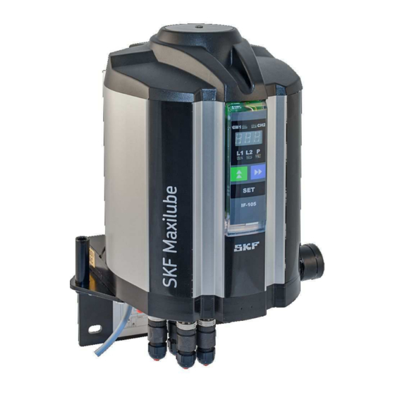
Page 18: Skf Maxilube Changeover Valve Unit
7.2 SKF Maxilube changeover valve unit The changeover valve unit includes a solenoid valve group (4) and a control valve group (2), pressure gauges (7) and a fixing plate which contains a bracket for the pump during the changing of the barrel. The Maxilube pumping centre includes a user interface (5) and a circuit board (3). -
Page 19: Operation
8 Operation 8.1 Operation of the pumping centre When pressurisation starts, control unit opens both the line to be pressurised and the pump solenoid valves. Pneumatic system starts the pump and opens the line control valve. Pressurisation continues until the pres- sure at the pressure monitoring unit reaches a pre-set acknowledgement level. -
Page 20: Maxilube With Eco Lid Set
8.2.1 Maxilube with ECO lid set Ensure that the surroundings of the pumping centre are clean. Impurities in the system prevent trouble- free operation and cause damage at the lubrication point. Check the condition of the lubricant barrel. Damages on the surface prevent the follower plate from being lowered (3, Figure 5). -
Page 21: Maxilube With Sta Lid Set
8.2.2 Maxilube with STA lid set 1. Ensure that the surroundings of the pumping centre are clean. Impurities in the system prevent trouble- free operation and cause damage at the lubrication point. 2. Check the condition of the lubricant barrel. Damages on the surface prevent the follower plate from being lowered (3, Figure 6). -
Page 22: Replacing The Lubricant Barrel
8.3 Replacing the lubricant barrel WARNING Pressurised lubricant Ensure that the system will not start during barrel replacement. Turn off the air supply by lifting the shut-off valve button (1, Figures 7 & 8) or set air pressure to 0 bar using the pressure regulator (2, Figures 7 & 8) and the pressure gauge (3, Figures 7 &... -
Page 23: Maxilube Sta
8.3.2 Maxilube STA 1. Ensure that the surroundings of the pumping centre are clean. Impurities in the system prevent trouble- free operation and cause damage at the lubrication point. 2. Switch off the power on the pumping centre when replacing the barrel. 3. -
Page 24: Manual Operation
8.4 Manual operation SKF Maxilube pumping centre can be operated by a manual procedure in the event of an electrical malfunc- tion or when commissioning before electrification. Pressurise the system by using the manual control screws of the pumping centre's solenoid valve group. -
Page 25: If-105 User Interface
9 IF-105 user interface 9.1 General information IF-105 is the user interface for the internal control unit of SKF Maxilube change over valve unit. Lubrication programming, alarm resetting and lubrication event monitoring can be performed with the user in- terface. -
Page 26: Led-Signals For Channels
9.3 LED-signals for channels Note LED-signals CH1 and CH2 for lubrication channels are in use only in systems with two chan- nels. LED-signal Description Red LED-signal is lit, when channel 1 is in alarm mode. Green LED-signal is lit, when channel 1 is in normal mode. LED-signal is blinking when channel 1 is selected on the display. -
Page 27: Buttons
9.5 Buttons Note The buttons affect only the channel which is selected on the display. Button Description In normal mode, the button is used to browse set values on the display. In setting mode, the button is used to change the value on the display. ... -
Page 28: If-105 Operation
10 IF-105 operation 10.1 Normal mode 10.1.1 Functions Display power saving mode In normal mode, the display shifts to power saving mode when no buttons have been used for ten (10) minutes. In power saving mode only the decimal points are blinking on the display. Lubrication events are per- formed according to the set values. -
Page 29: Phase Codes For Normal Mode And Alarm Mode
(line pressure is not low enough when pressurization phase starts) (Alarm, High, Pressure) Alarm from doser operation indicator (SKF Doser monitor). The code is displayed only if SKF Doser monitors are in use. (Alarm, Indicator) Alarm from the air pressure switch of the grease spray system. -
Page 30: Normal Mode Displays, Monoflex And And Duoflex Lubrication Systems
10.1.3 Normal mode displays, MonoFlex and and DuoFlex lubrication systems Normal mode displays, which show the set values for the lubrication program, can be browsed with the -but- ton. Display codes change in the following order when -button is pressed. Display code Description The lubrication channel selected on the display. -
Page 31: Normal Mode Displays, Progressive Lubrication System
10.1.4 Normal mode displays, Progressive lubrication system Normal mode displays, which show lubrication program set values, can be browsed with the -button. Display codes change in the following order when -button is pressed. Display code Description The lubrication channel selected on the display. Press the SET-button to go to another channel when the code is displayed. -
Page 32: Pressure And Pulse Displays For Lines
10.1.5 Pressure and pulse displays for lines Pressure transmitter operation In pressure transmitter operation, line pressure displays can be selected with the -button. Pressing the but- ton will show the pressure display for line 1 first. Code P1 and the pressure display for line 1 are displayed in turns. -
Page 33: Pulse Alarm, Proflex Lubrication System
10.3.4 Alarm from SKF Doser monitor -doser operation indicator The SKF Doser monitors are in use when factory settings parameter LGI has been set in status YES. An alarm will be triggered when the SKF Doser monitor does not recognize doser operation during a lubrica- tion cycle. -
Page 34: Alarm From The Air Pressure Switch Of The Grease Spray System
HL in status OFF • automatically when 60 minutes have elapsed since going into manual operation mode • restart SKF Maxilube hydraulic part or SKF ST-1240-IF control center In manual operation mode SET-button is used to: • start pumping •... -
Page 35: If-105 Settings
11 IF-105 settings 11.1 General Set values are lubrication channel basic values, for example lubrication cycle and maximum pressurization time. Set values are channel specific. All settings are password-protected. 11.2 Entering password 15 Select the code for the setting to be changed on the display with the -button. 16 Press the SET-button. -
Page 36: If-105 Technical Specification
minutes. Decimal point of the set value can be moved as follows. 33 Select the code for the setting to be changed on the display with the -button. 34 Press the SET-button. 35 Set the desired value with the - and -buttons. 36 Press the -button. -
Page 37: Maxilube Troubleshooting
13 Maxilube troubleshooting Operation disturbance Cause of operation distur- Solution bance If internal control unit of SKF Max- ilube is in use: Display and LED-signals of the No supply voltage at the pump- Check the supply voltage. user interface are not lit. - Page 38 The control valve at the hydrau- Check that the set values for high lic part does not operate. and low limit pressure are correct. Contact Oy SKF Ab when neces- sary. Check the pressure of the pressure air. Check the operation of the sole- noid valves MV1 and MV2.
- Page 39 Figure 4 Shut off valve button (e) Figure 5 Grease filter (10), venting screw (11)
-
Page 40: Maxilube Technical Specification
14 Maxilube technical specification 14.1 Technical specifications Maxilube changeover valve unit Quantity Value Unit Description 0…+50 °C Ambient temperature range +32…+122 °F 2–4.5 Operating air pressure range 40–65 24 ±10% V DC Control voltage 115 ±10%; 50/60 V AC; Hz 230 ±10%;... -
Page 41: Connections
14.2 Connections 14.2.1 SKF Maxilube changeover valve unit Inputs • A1: pressure air, ø8 mm push in connector (G1/8) • D: low level switch, connector M12 • P1, P2: pressure control, 2 pcs, connector M12 • power input, M20x1,5 cable gland Outputs •... -
Page 42: Designations - Maxilube Changeover Valve Unit
14.3 Designations – Maxilube changeover valve unit MAX-A-B-C-D-E-F Abbreviation Description MAX: SKF Maxilube changeover valve set Number of channels (1 channel) Number of channels (2 channels) Number of lines (single-line system) Number of lines, dual-line system Control voltage 24 V... - Page 43 Table 1 Order codes for the SKF Maxilube changeover valve unit with internal control Order code Designation Description 12371171 MAX-1-2-230-IF105-R-V2 One channel, dual line, 230 V AC, with control, ø12 mm pipe out- lets 12371501 MAX-1-2-230-IF105-U-V2 One channel, dual line, 230 V AC, with control, ø1/2" pipe outlets...
-
Page 44: Periodic Inspections
– Check the air pressure and the condition of the air lines. – Check that the grease filter and the hydraulic lines connected to the pump outlet are not clogged. – If the problem persists, contact your Oy SKF Ab representative. -
Page 45: Troubleshooting Table
Check the air supply hoses for leaks. A lot of grease leaks from the hole Damaged seal. Contact your Oy SKF Ab repre- (11) at the bottom of the cylinder sentative. block (1) (see Figure 2). Small leaks require no measures. -
Page 46: Shutdown, Decommissioning And Storage
Observe any local laws and regulations concerning disposal and recycling. You can also return the product to Oy SKF Ab for disposal. Oy SKF Ab reserves the right to recover any costs arising from the disposal. -
Page 47: Spare Parts
18 Spare parts Item Description Order code Control valve CHV-100 control cartridge (1 or 2 pcs) 12386245 Circuit board ST105A 12501460 Solenoid valve 24 V 12602170 User interface IF-105 12501480 Power supply 115/230VAC 11501000 12600850 Pressure gauge Figure 7: Spare parts for Maxilube...
Need help?
Do you have a question about the MAX-1-2-230-IF105-R-V2 and is the answer not in the manual?
Questions and answers