Table of Contents
Advertisement
Quick Links
Assembly Instructions
Gear Pump Units of Product Series
MKU, MKF, MKL
for oil and fluid grease for use in SKF MonoFlex single-line and oil+air centralized lubrication systems
Created on:
05.07.2022
Document no.:
951-170-248-EN
Version:
01
Read these instructions before
installation or start-up of the
product and keep them readily
available for later consultation!
Advertisement
Table of Contents

Related Manuals for SKF MKU Series


Summary of Contents for SKF MKU Series
- Page 1 Assembly Instructions Gear Pump Units of Product Series MKU, MKF, MKL for oil and fluid grease for use in SKF MonoFlex single-line and oil+air centralized lubrication systems Created on: 05.07.2022 Document no.: 951-170-248-EN Version: Read these instructions before installation or start-up of the...
- Page 2 The special technical documents were prepared following Annex VII part B. Upon justifiable request, these special technical documents can be forwarded electronically to the respective national authorities. The authorized company for the compilation of the technical documentation is SKF (U.K.) Limited, 2 Canada Close, Banbury, Oxfordshire, OX16 2RT, GBR.
- Page 3 Appendix to Declaration of Incorporation in accordance with 2006/42/EC, Annex II, No. 1 B Description of the essential health and safety requirements according to 2006/42/EC, Annex I, which have been applied and fulfilled. Any essential health and safety requirements not listed here are not relevant to this product. Table 1 Appendix to Declaration of Incorporation No.:...
-
Page 4: Masthead
Training www.skf.com/lubrication We conduct detailed training in order to enable maximum safety and efficiency. We recommend taking advantage of this Berlin Plant training. For further information, contact your authorized SKF Motzener Strasse 35/37 dealer or the manufacturer. 12277 Berlin Germany Tel. -
Page 5: Table Of Contents
5.4 Storage temperature range ..........24 Table of contents 5.5 Storage conditions for products filled with lubricant ..24 5.5.1 Storage period up to 6 months ......24 Masthead ..................... 4 5.5.2 Storage period between 6 and 18 months ..24 Table of contents ................ - Page 6 11.1 Prior to beginning troubleshooting ........57 11.2 Replacing a defective fuse (24 VDC) ........ 57 11.3 Commissioning, product, and system malfunctions ..58 12. Repairs ..................60 13. Shutdown, disposal ..............60 13.1 Temporary shutdown ............60 13.2 Permanent shutdown, disassembly ........ 60 13.3 Disposal ................
-
Page 7: Safety Alerts, Visual Presentation, And Layout
1. Instruction steps: These indicate a chronological sequence Safety alerts, visual of instruction steps. The numbers of the steps are in bold and are followed by a period. If a new activity follows, the presentation, and layout numbering starts again at “1.” –... -
Page 8: Safety Instructions
Only • If protective and safety equipment has to be dismantled, it original SKF spare parts and SKF accessories may be used. must be reassembled immediately after finishing the work, • Any unclear points regarding proper condition or correct and then checked for correct function. -
Page 9: Foreseeable Misuse
Immediately replace warning labels if damaged or missing. The 1.6 Foreseeable misuse product must not be operated until then. Any usage of the product other than as specified in this manual is strictly prohibited. Particularly prohibited are: Fig. 1 • Use of non-specified consumables, contaminated lubricants, or lubricants with air inclusions. -
Page 10: Note On Low Voltage Directive
• 2014/30/EC Electromagnetic Compatibility • Unauthorized persons must be kept away • 2011/65/EU Directive on the restriction of the use of certain • Mark and secure the work area hazardous substances in electrical and electronic equipment • Cover adjacent live parts (RoHS II) •... -
Page 11: Residual Risks
1.20 Residual risks Table 3 Residual risks Residual risk Possible in lifecycle Avoidance / Remedy Electric shock due to defective power B C D Inspect the power lead/power plug for damage before lead/mains plug starting the product People slipping due to floor B C D F G H K •... -
Page 12: Lubricants
Solid lubricants may only be used after prior consultation with make the selection in consultation with the supplier of the SKF. When solid lubricants are used in lubrication systems, the lubricant. If you have no or little experience in selecting following rules generally apply: lubricants for lubrication systems, please contact us. -
Page 13: Overview, Functional Description
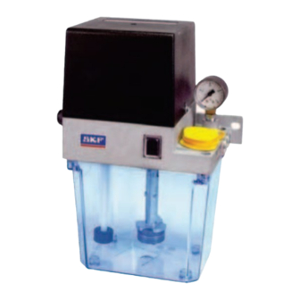
(plastic = 2-, 3- and 6-liter rated capacity, metal= 3-liter rated 3. Overview, functional capacity), a pressure switch (Fig. 7/2) for electrical pressure monitoring, a fill level switch (Fig. 8/8) monitoring the minimum description fill level, and a pressure gauge (Fig. 9/3) for visual pressure monitoring. -
Page 14: Description Of Designs
Detailed information about the function and the electrical connection of the gear pump unit is included in Chapter 4 of the assembly instructions. The documentation can also be requested directly from SKF Lubrication Systems Germany GmbH. 3.3 Description of designs gear pump unit . -
Page 15: Gear Pump Unit Without Control Unit
the ability to evaluate the signal from an external air pressure operating time after certain periods of time specified by the switch to monitor the oil+air system. The electrical connections operator. are established via DIN connection plugs or screwed glands. Depending on the model design, the electronic control unit could allow configuration of the interval time, the pump delay time, and the number of prelubrication cycles. - Page 16 Table 4 Table 6 Parameters of the IG38-30-I IGZ36-20-S6-I parameters Designation Default Setting via Setting range Designation Abbreviation Default Setting range Interval time 1 min Rotary switch 1 – 2048 min (in Operating B (pulse binary mode generator) increments) D (pulse counter) Monitoring 60 sec Not adjustable + 3000 min...
-
Page 17: Lubrication Systems
3.7 Lubrication systems Fig. 18 Fig. 17 Relubrication distributor system 3.7.1 General Prelubrication metering device system Gear pump units are generally used for single-line systems with piston metering devices. Single-line systems with piston distributors are total-loss lubrication systems. 3.7.2 Total-loss lubrication systems Total-loss lubrication systems feed clean lubricant (oil, fluid grease or grease) to one or more lubrication points at specific intervals (dependent on time or machine cycle) during the... -
Page 18: Single-Line Lubrication Systems With Piston Metering Devices
3.7.3 Single-line lubrication systems with 3.7.5 Lubrication cycle of relubrication piston metering devices metering device Single-line systems with piston metering devices generally After the electric motor is switched on, the lubricant is drawn consist of a reservoir unit, and here include a gear pump unit, out of the lubricant reservoir by the gear pump and fed through piston metering devices, and lubrication lines. -
Page 19: Technical Data
4. Technical data 4.1 Technical connection data Table 8 Technical connection data Designation Value <Content> Reservoir capacity 2, 3 and 6 liters Reservoir material MKU, MKL Plastic or metal Plastic Weight empty Unit with 2-liter plastic reservoir 3.4 kg Unit with 3-liter plastic reservoir 4.2 kg Unit with 3-liter metal reservoir 5 kg... -
Page 20: Order Code For Mku Gear Pump Units
Table 8 Technical connection data Designation Value <Content> Lubricant level switch for oil (opens when fill level is too low) Switching voltage range 10 to 36 V DC / 10 to 25 V AC Switched current (resistive load) ≤ 0.25 A Pumped media switching capacity (resistive load) ≤... - Page 21 M K U 0 0 0 + Control " " " " Without control unit, with terminal strip " " " " Without control unit, with terminal strip and pushbutton " " " IG38-30-I " " " IZ38-30-I " " "...
-
Page 22: Order Code For Mkf Gear Pump Units
4.3 Order code for MKF gear pump units M K F 0 0 0 + Product series MK MKx pump Lubricant for fluid grease Delivery rate " " 0.1 l/min " " 0.2 l/min Lubricant reservoir, control unit Lubricant reservoir 2 liter plastic 3 liter plastic 6 liter plastic Control... -
Page 23: Order Code For Mkl Gear Pump Units
If control E is selected, only electrical connection 1 can be selected. Possible only with delivery rates 0.1 and 0.2 l/min. Only on design without control unit. Order example: MKF1-11AC10000+924 • Gear pump unit for fluid grease • without control unit, with terminal strip •... -
Page 24: Delivery, Returns, Storage
5.5 Storage conditions for products filled 5. Delivery, returns, storage with lubricant 5.1 Delivery For products filled with lubricant, the permitted storage temperature range is: After receipt of the shipment, it must be inspected for any minimum + 5 °C [+41 °F] shipping damage and for completeness according to the maximum... -
Page 25: Assembly
See the "Technical data" for the gear pump unit in these assembly instructions. These documents can be downloaded NOTICE from the homepage of SKF Lubrication Systems Germany Observe the technical data GmbH. For assembly, observe the technical specifications in the The mounting position of the gear pump unit is vertical as "Technical data";... -
Page 26: Assembly Drawing With Minimum Mounting Dimensions
6.4 Assembly drawing with minimum mounting dimensions 6.4.1 MKU/MKF gear pump units with 2-liter plastic reservoir for oil and fluid grease Fig. 20 MKU/MKF gear pump units with 2-liter plastic reservoir for oil and fluid grease Legend to Figure 20: A Width B Height (clearance for lid removal) C Depth... -
Page 27: Mku/Mkf/Mkl Gear Pump Units With 3-Liter Plastic Reservoir For Oil And Fluid Grease
6.4.2 MKU/MKF/MKL gear pump units with 3-liter plastic reservoir for oil and fluid grease Fig. 21 Gear pump unit with 3-liter plastic reservoir for oil and fluid grease Legend to Figure 21: A Width B Height (clearance for lid removal) C Depth X Assembly holes Minimum mounting dimensions:... -
Page 28: Mku/Mkf/Mkl Gear Pump Units With 3-Liter Metal Reservoir For Oil And Fluid Grease
6.4.3 MKU/MKF/MKL gear pump units with 3-liter metal reservoir for oil and fluid grease Fig. 22 Gear pump unit with 3-liter metal reservoir for oil and fluid grease Legend to Figure 22: A Width B Height (clearance for lid removal) C Depth X Assembly holes Minimum mounting dimensions:... -
Page 29: Mku/Mkf/Mkl Gear Pump Units With 6-Liter Plastic Reservoir For Oil And Fluid Grease
6.4.4 MKU/MKF/MKL gear pump units with 6-liter plastic reservoir for oil and fluid grease Fig. 23 Gear pump unit with 3-liter plastic reservoir for oil and fluid grease Legend to Figure 23: A Width B Height (clearance for lid removal) C Depth X Assembly holes Minimum mounting dimensions:... -
Page 30: Connection Examples
6.5 Connection examples 6.5.1 MKF hydraulic connection Fig. 24 Example of MKF hydraulic connection M K F x - 1 x A X 0 x 0 0 0 + x x x M K F x - 1 x C C 1 x 0 0 0 + x x x without optional pressure with pressure gauge gauge... -
Page 31: Mkl Hydraulic Connection
6.5.3 MKL hydraulic connection Fig. 26 Example of MKL hydraulic connection M K L x - 1 x F C 0 x 0 0 0 + x x x M K L x - 1 x F C 1 x 0 0 0 + x x x without optional pressure with pressure gauge gauge... -
Page 32: Electric Motor Connection
6.7.1 Electric motor connection NOTICE Overvoltage Consult the motor's type plate for the electrical characteristics of Damage and injury due to improper connection of the the motor. supply voltage Observe the guidelines in EN 60034-1 (VDE 0530-1) for • The available line voltage (supply voltage) must match operation at the limits of the ranges A (combination of the specifications on the rating plate of the motor or the ±5 % voltage deviation and ±2 % frequency deviation) and B... -
Page 33: Electric Motor Connection With Cable Socket And Circular Connector
6.8 Terminal diagrams In the case of electric switches with inductive loads, the 6.8.1 Legend to the terminal diagrams inductivity of the switch must be low in order to keep wear on contact surfaces to a minimum. Otherwise, there is a risk of Table 9 damaging the contact surfaces on the switch elements. -
Page 34: Terminal Diagrams For Mku/Mkf, Without Control Unit
6.8.2 Terminal diagrams for MKU/MKF, Fig. 29 without control unit 6.8.2.1 MKU, 2-liter reservoir, voltage design 230/115 VAC, without pushbutton Connections via: • 2x screwed glands Fig. 32 XS1 connector, XS2 connector Fig. 30 MKU1-11A _ _ 0000+428/+429, MKU1-11A _ _ 3000+428/+429 Connections via: •... - Page 35 Connections via: Connections via: • XS1 connector (DIN EN 175301-803 A) • 1x connector XS1 (DIN EN 175301-803 A) • XS2 connector (M12x1) • 1x screwed gland Fig. 34 Fig. 36 MKU1-11A _ _ 2000+428/+429 MKU1-11B _ _ 1000+428/+429, MKU1-11B _ _ 4000+428/+429 6.8.2.2 MKU, 2-liter reservoir, voltage design Connections via:...
- Page 36 6.8.2.3 MKU, 2-liter reservoir, voltage design 24 VDC, Connections via: • XS1 connector (DIN EN 175301-803 A) without pushbutton • XS2 connector (M12x1) Connections via: Fig. 40 • 2x screwed glands Fig. 38 MKU1-11A _ _ 2000+924 MKU1-11A _ _ 0000+924, MKU1-11A _ _ 3000+924 6.8.2.4 MKU, 2-liter reservoir, voltage design 24 VDC, with pushbutton Connections via:...
- Page 37 Connections via: 6.8.2.5 MKF, 2-liter reservoir, voltage design • 1x connector XS1 (DIN EN 175301-803 A) 230/115 VAC, without pushbutton • 1x screwed gland Connections via: Fig. 42 • 2x screwed glands Fig. 44 MKU1-11B _ _ 1000+924, MKU1-11B _ _ 4000+924 MKF1-11A _ _ 0000+428/+429, MKF1-11A _ _ Connections via: •...
- Page 38 Connections via: Connections via: • XS1 connector (DIN EN 175301-803 A) • 1x connector XS1 (DIN EN 175301-803 A) • XS2 connector (M12x1) • 1x screwed gland Fig. 46 Fig. 48 MKF1-11A _ _ 2000+428/+429 MKF1-11B _ _ 1000+428/+429, MKF1-11B _ _ 4000+428/+429 6.8.2.6 MKF, 2-liter reservoir, voltage design 230/115 VAC, with pushbutton...
- Page 39 6.8.2.7 MKF, 2-liter reservoir, voltage design Connections via: • XS1 connector (DIN EN 175301-803 A) 24 V DC, without pushbutton • XS2 connector (M12x1) Connections via: Fig. 52 • 2x screwed glands Fig. 50 MKF1-11A _ _ 2000+924 MKF1-11A _ _ 0000+924, MKF1-11A _ _ 3000+924 6.8.2.8 MKF, 2-liter reservoir, voltage design 24 VDC, with pushbutton Connections via:...
- Page 40 Connections via: 6.8.2.9 MKU, 3- or 6-liter reservoir, voltage design • 1x connector XS1 (DIN EN 175301-803 A) 230/115 VAC, without pushbutton • 1x screwed gland Connections via: Fig. 54 • 2x screwed glands Fig. 56 MKF1-11B _ _ 1000+924, MKF1-11B _ _ 4000+924 MKU1 -12(3) A _ _ 0000+428/+429, MKU2(5)-12(3)(4)A _ _ 0000+428/+429, MKU2(5)-12(3)(4)A _ _ 3000+428/+429 Connections via:...
- Page 41 Connections via: Connections via: • XS1 connector (DIN EN 175301-803 A) • 1x connector XS1 (DIN EN 175301-803 A) • XS2 connector (M12x1) • 1x screwed gland Fig. 58 Fig. 60 MKU1 -12(3) A _ _ 2000+428/+429, MKU2(5)-12(3)(4)A _ _ MKU1 -12(3) B _ _ 1000+428/+429, MKU2(5)-12(3)(4)B _ _ 2000+428/+429 1000+428/+429, MKU2(5)-12(3)(4)B _ _ 4000+428/+429...
- Page 42 6.8.2.11 MKU, 3- or 6-liter reservoir, voltage design Connections via: • XS1 connector (DIN EN 175301-803 A) 24 VDC, without pushbutton • XS2 connector (M12x1) Connections via: Fig. 64 • 2x screwed glands Fig. 62 MKU1-12(3) A _ _ 2000+924, MKU2-12(3)(4)A _ _ 2000+924 MKU1-12(3) A _ _ 0000+924, MKU2-12(3)(4)A _ _ 0000+924, 6.8.2.12 MKU, 3- or 6-liter reservoir, voltage design MKU2-12(3)(4)A _ _ 3000+924...
- Page 43 Connections via: 6.8.2.13 MKF, 3- or 6-liter reservoir, voltage design • 1x connector XS1 (DIN EN 175301-803 A) 230/115 VAC, without pushbutton • 1x screwed gland Connections via: Fig. 66 • 2x screwed glands Fig. 68 MKU1-12(3) B _ _ 1000+924, MKU2-12(3)(4)B _ _ 1000+924, MKU2-12(3)(4)B _ _ 4000+924 MKF1-12 A _ _ 0000+428/+429, MKF2-12(4)A _ _ Connections via:...
- Page 44 Connections via: Connections via: • XS1 connector (DIN EN 175301-803 A) • 1x connector XS1 (DIN EN 175301-803 A) • XS2 connector (M12x1) • 1x screwed gland Fig. 70 Fig. 72 MKF1-12 B _ _ 1000+428/+429, MKF2-12(4)B _ _ MKF1-12 A _ _ 2000+428(+429), MKF2-12(4)A _ _ 1000+428/+429, MKF2-12(4)B _ _ 4000+428/+429 2000+428(+429) Connections via:...
- Page 45 6.8.2.15 MKF, 3- or 6-liter reservoir, voltage design Connections via: • XS1 connector (DIN EN 175301-803 A) 24 VDC, without pushbutton • XS2 connector (M12x1) Connections via: Fig. 76 • 2x screwed glands Fig. 74 MKF1-12 A _ _ 2000+924, MKF2-12(4)A _ _ 2000+924 MKF1-12 A _ _ 0000+924, MKF2-12(4)A _ _ 0000+924, 6.8.2.16 MKF, 3- or 6-liter reservoir, voltage design MKF2-12(4)A _ _ 3000+924...
-
Page 46: Terminal Diagrams For Mku/Mkf/Mkl, 3- Or 6-Liter Reservoir, With Control Unit
Connections via: 6.8.3 Terminal diagrams for MKU/MKF/MKL, • 1x connector XS1 (DIN EN 175301-803 A) 3- or 6-liter reservoir, with control unit • 1x screwed gland Fig. 78 6.8.3.1 MKU, IG/IZ38 control unit, voltage design 230/115 VAC Connections via: • 2x screwed glands Fig. -
Page 47: Mkf, Ig/Iz38 Control Unit, Voltage Design 230/115 Vac
6.8.3.3 MKU, IGZ36 control unit, voltage design Table 11 24 VDC Settings • Connections via: Assignment Operation • 1x connector XS1 (DIN EN 175301-803 A) <Content> • 1x screwed gland d2:12 Fault Fig. 83 d2:24 Normal operation d2:22 Fault 1) Machine contact MK is only required in counter mode (IZ38- 30-I control unit) 2) The control unit can be switched between 230 V and 115 V AC. - Page 48 6.8.4.1 MKF, IGZ36 control unit, voltage design Table 14 230/115 VAC Settings Connections via: Assignment Operation • 1x connector XS1 (DIN EN 175301-803 A) <Content> • 1x screwed gland d2:12 Fault Fig. 86 d2:24 Normal operation d2:22 Fault Connections via: •...
-
Page 49: Lubrication Line Connection
6.8.4.2 MKF, IGZ36 control unit, voltage design 24 VDC Table 18 Connections via: Settings • 1x connector XS1 (DIN EN 175301-803 A) Assignment Operation • 1x screwed gland <Content> Fig. 87 X1:16 Fault or completion of prelubrication cycles X1:14 Normal operation 1) Customer-connectable air pressure switch DL, compressed- air valve Y1 2) The control unit can be switched between 230 V and... -
Page 50: Assembly Of The Main Lubrication Line With Cone Ring Fitting
Fig. 90 The SKF quick couplings are available in designs for metal pipes or plastic tubing. The claw groove securely fastens the pipe in the quick disconnect coupling, which prevents the metal pipe from slipping out of the SKF quick disconnect coupling. -
Page 51: System Criteria For Mkl Gear Pump Unit
Fig. 92 2. Insert the tube (Fig. 91 or 92/1) fully into the collet (Fig. 91 or 92/2) of the SKF quick coupling until it passes the first O-ring (Fig. 91 or 92/3) and the locking claw (Fig. 91 or 92/4) of the collet (Fig. 91 or 92/2) and reaches the mechanical stop (Fig. -
Page 52: Venting An Mku/Mkf/Mkl Centralized Lubrication System
6.14 Venting an MKU/MKF/MKL NOTICE centralized lubrication system Observe the safety data sheet Follow the safety instructions on the lubricant's safety data Fig. 93 sheet When routing the main lubricant lines and the feed lines, observe the following instructions in order to ensure that the entire centralized lubrication system functions smoothly. -
Page 53: First Start-Up
7. First start-up Inspect all electrical and hydraulic connections before putting the product into operation. The lubricant reservoir must be filled with clean lubricant without introducing bubbles. The gear pump unit should be operated only approx. 15 min. after filling in order to allow possible air pockets to escape. -
Page 54: Operation
8.2 Intermediate lubrication pushbutton 8. Operation Fig. 94 NOTICE Contaminated lubricant Damage due to contaminated lubricant Only fill using clean lubricant and an appropriate device. Contaminated lubricants lead to system malfunctions. The lubricant reservoir must be filled without introducing bubbles. NOTICE Mixing lubricants Damage from mixing lubricants... -
Page 55: Maintenance And Repair
• Regularly inspect the Incorrect spare parts system components for Nullification of warranty leaks Only original SKF spare parts may be used. Unauthorized Pump • Inspect electrical cables for alterations and the use of non-original spare parts and damage accessories are prohibited and nullify the statutory •... -
Page 56: Cleaning
10. Cleaning 10.1 Basics Cleaning should be carried out in accordance with the operator's own company rules, and cleaning agents and devices and the personal protective equipment to be used should likewise be selected in accordance with those rules. Only cleaning agents compatible with the materials may be used for cleaning. -
Page 57: Faults, Causes, And Remedies
The following tables provide an overview of possible 11. Faults, causes, and malfunctions and their causes. Contact the SKF Service department if you cannot remedy the malfunction. remedies 11.1 Prior to beginning troubleshooting WARNING Electric shock If the gear pump unit does not pump, first check the customer’s Performing work on products that have not power supply. -
Page 58: Commissioning, Product, And System Malfunctions
3. Loosen screws on both sides of the motor's cover cap using a 7. Push the bayonet closure (Fig. 95/1) of the fuse housing into screwdriver the fuse box and turn it clockwise to seal 4. Carefully lift the cover cap and put it aside 8. - Page 59 No pressure build up in the main line Pressure-relief valve does not close • Clean or replace the pressure-relief valve. Only use original SKF spare parts Impermissible lubricant, see technical data) • Remove the lubricant from the entire system and dispose of lubricant properly;...
-
Page 60: Repairs
12. Repairs < WARNING Risk of injury At a minimum, the following safety measures must be taken before any repairs: • Unauthorized persons must be kept away • Mark and secure the work area • Depressurize the product • Isolate the product, and lock and tag it out •... -
Page 61: Spare Parts
14. Spare parts Spare parts may be used exclusively for replacement of identical defective parts. Modifications with spare parts on existing products are not allowed. Fig. 96 Spare parts... - Page 62 Table 23 Spare parts Units Material number Designation Description 996-000-947 Pressure limiting valve 32 bar for oil 996-002-197 Pressure limiting valve 30 bar for fluid grease MKF.U012 Pressure relief, compl. for fluid grease for fluid grease MKU.U012 Pressure relief, compl. for oil for oil MKF.U013 Pressure gauge for fluid grease...
-
Page 63: Accessories
Table 23 Spare parts Units Material number Designation Description 18 * IG38-30-I+XXX Control unit for time-dependent control (only for 3- and 6- liter units) IZ38-30-I+XXX Control unit for load-dependent control (only for 3- and 6- liter units) IGZ36-20-S6-I+XXX Control unit Pulse generator/pulse counter (only for 3- and 6-liter units) IG54-20-S4-I+XXX... - Page 64 Table 24 Filling device Description Order No. Filling device, complete, with banjo fitting 995-000-800 Coupling socket (for refill connection) 995-001-500 Sealing ring DIN7603-A14x18-CU Hose connector for connection to coupling socket d ø13 857-760-007 d ø16 857-870-002 Fig. 99 Main line connections Table 25 Main line connections Description...
- Page 65 Fig. 100 pipe cutter Table 26 pipe cutter pipe cutter cutting ring for pipe ø Order No. Order No. For plastic tubing 169-000-301 For steel tubing with claw groove 4 169-000-336 844-330-006 169-000-337 844-330-007 169-000-338 844-330-007 Fig. 101 Rectangular connector and cable sockets Table 27 Rectangular connector and cable sockets Designation...
- Page 66 Table 27 Rectangular connector and cable sockets Designation Order No. Weight [g] Cable sockets M12x1, 4-pin design, without LED Circular connector, straight, without cable, diameter 4-6 mm, 4-pin, max. 0.75 mm² 2360-00000316 Circular connector, straight, with 5-m integrally extruded cable, 4-pin, 4×0.25 mm² 179-990-600 Circular connector, straight, with 10-m integrally extruded cable, 4-pin, 4×0.25 mm²...
-
Page 67: Appendix
15. Appendix 15.1 China RoHS Table Table 28... - Page 68 ® SKF is a registered trademark of the SKF Group. ™ eLube is a trademark of the SKF Group. © SKF Group 2023 Reprint or reproduction of the contents of this information - even in part - is permitted only with SKF's prior written consent.
Need help?
Do you have a question about the MKU Series and is the answer not in the manual?
Questions and answers