
Related Manuals for SKF MAXILUBE MAX 230-IF105 Series


Summary of Contents for SKF MAXILUBE MAX 230-IF105 Series
- Page 1 Assembly Instructions MAXILUBE CHANGEOVER VALVE UNIT Date: 11.8.2022 Document no.: MAXILUBE Version: 2D Read this manual before installing or commissioning the product and keep it at hand for later reference!
- Page 2 The special technical documents were prepared following Annex VII part B. Upon justifiable request, these special technical documents can be forwarded electronically to the respective national authorities. The authorized company for the compilation of the technical documentation is SKF (U.K.) Limited, 2 Canada Close, Banbury, Oxfordshire, OX16 2RT, GBR. Designation:...
- Page 3 The special technical documents were prepared following Annex VII part B. Upon justifiable request, these special technical documents can be forwarded electronically to the respective national authorities. The authorized company for the compilation of the technical documentation is SKF (U.K.) Limited, 2 Canada Close, Banbury, Oxfordshire, OX16 2RT, GBR. Designation:...
- Page 4 Appendix to Declaration of Incorporation in accordance with 2006/42/EC, Annex II, No. 1 B Description of the essential health and safety requirements according to 2006/42/EC, Annex I, which have been applied and fulfilled. Any essential health and safety requirements not listed here are not relevant to this product Table 1 Appendix to Declaration of Incorporation Valid for: MAXILUBE changeover valve units...
-
Page 5: Masthead
The instructions contain no statements regarding the warranty or liability for defects. That information can be found in our General Terms of Payment and Delivery. Training We conduct detailed training in order to enable maximum safety and efficiency. We recommend taking advantage of this training. For further information, contact your authorized SKF dealer or the manufacturer. -
Page 6: Table Of Contents
Avoidance of faults and hazards ............................14 Solid lubricants ..................................15 3. General description ................................... 16 Maxilube pumping centre ..............................16 SKF Maxilube changeover valve unit ........................... 17 4. Operation ....................................18 Operation of the pumping centre ............................18 Commissioning ..................................18 4.2.1 Connections ................................ - Page 7 8. Maxilube technical specification ............................... 45 Technical specification Maxilube changeover valve unit ..................... 45 Symbols Maxilube changeover valve unit ..........................46 Order codes, SKF Maxilube changeover valve unit ......................47 9. Maintenance ..................................... 48 Cleaning ....................................48 9.1.1 Basics ..................................48 9.1.2 Interior cleaning .................................
-
Page 8: Safety Alerts, Visual Presentation, And Layout
Safety alerts, visual presentation, and layout While reading these instructions, you will encounter various symbols, illustrations, and text layouts intended to help you navigate and understand the instructions. Their meaning is explained below. Safety alerts: Activities that present specific hazards (to life and limb or possible damage to property) are indicated by safety alerts. Always be sure to follow the instructions given in the safety alerts. -
Page 9: Safety Instructions
• Unauthorized modifications and changes can have an unpredictable effect on safety and operation. Unauthorized modifications and changes are therefore prohibited. Only original SKF spare parts and SKF accessories may be used. • Any unclear points regarding proper condition or correct assembly/operation must be clarified. Operation is prohibited until issues have been clarified. -
Page 10: Persons Authorized To Use The Product
Persons authorized to use the product Operator A person who is qualified by training, knowledge and experience to carry out the functions and activities related to normal operation. This includes avoiding possible hazards that may arise during operation. Specialist in mechanics Person with appropriate professional education, knowledge and experience to detect and avoid the hazards that may arise during transport, installation, start-up, operation, maintenance, repair and disassembly. -
Page 11: Notes On The Type Plate
Notes on the type plate The type plate provides important data such as the type designation, order number, and sometimes regulatory characteristics. To avoid loss of this data in case the type plate becomes illegible, it should be entered in the manual. Fig. -
Page 12: Notes Related To The Ukca Marking
Notes related to the UKCA marking The UKCA conformity marking con- firms the product’s conformity with the applicable legal provisions of Great Britain. Note on EAC marking The EAC conformity marking confirms the product’s conformity with the applicable legal provisions of the Eurasian customs union. Note on China RoHS mark The China RoHS marking confirms that there is no danger to persons or the environment... -
Page 13: Residual Risks
Residual risks Table 2 Residual risks Residual risk Possible in life cycle Prevention/ remedy Personal injury/ material damage A B C G H K Keep unauthorized persons away. No people may due to falling of raised parts remain under suspended loads. Lift parts with adequate lifting devices. -
Page 14: Lubricants
• Whenever possible, always use SKF lubrication greases. They are ideal for use in lubrication systems. • Do not mix lubricants. This can have unpredictable effects on the properties and usability of the lubricant. -
Page 15: Solid Lubricants
Solid lubricants Solid lubricants may only be used after prior consultation with SKF. When solid lubricants are used in lubrication systems, the following rules generally apply: Graphite: • Maximum graphite content 8% • Maximum grain size 25 µm (preferably in lamellar form) MoS2: •... -
Page 16: General Description
3. General description Maxilube pumping centre The pumping centre of the SKF MaxiLube central lubrication system is designed for pumping lubricant into a centralised lubrication system. The pumping centre can be controlled and monitored using a control unit integrated in the changeover valve unit, by sending SMS messages or by means of external control. -
Page 17: Skf Maxilube Changeover Valve Unit
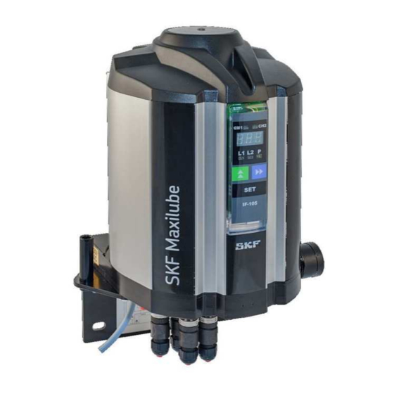
SKF Maxilube changeover valve unit The changeover valve unit includes a solenoid valve group (4) and a control valve group (2), pressure gauges (7) and a wall mounting plate which contains a bracket for the pump during the changing of the barrel. A Maxilube changeover valve unit with control includes a user interface (5) and a circuit board (3). -
Page 18: Operation
4. Operation Operation of the pumping centre When pressurisation starts, control unit opens both the line to be pressurised and the pump solenoid valves. The pneumatic system starts the pump and opens the line control valve. Pressurisation continues until the pressure at the pressure monitoring unit reaches a pre-set acknowledgement level. -
Page 19: Connections
4.2.1 Connections Lubricant connections: " lubricant outlets (1 or 2 pcs; line 1 out, line 2 out), G3/8”, hose Ø 12 mm or Ø 1/2” (L1, L2) " pressure inlet from the pump (G3/8), DIN 2353 shear ring coupling for a Ø 12 mm pipe (P) "... -
Page 20: Commissioning With Maxilube Ecolid Set And Mpb Pump
4.2.2 Commissioning with Maxilube ECOlid set and MPB pump Fig. 6 Maxilube, ECO lid set and MPB pump Ensure that the surroundings of the pumping centre are clean. Impurities in the system will prevent trouble-free operation and cause damage at the lubrication point. Reserve a container for excess grease. - Page 21 18. When you have completed these actions, you can fill/bleed the manifold/branch piping.
-
Page 22: Commissioning With Maxilube Stalid Set And Mpb Pump
4.2.3 Commissioning with Maxilube STA lidset and MPB pump Fig. 7 Maxilube, STA lid set and MPB pump Ensure that the surroundings of the pumping centre are clean. Impurities in the system will prevent trouble-free operation and cause damage at the lubrication point. Reserve a container for excess grease. -
Page 23: Replacing The Lubricant Barrel
Replacing the lubricant barrel < WARNING Pressurised lubricant Ensure that the system will not start during barrel replacement. Shut off the compressed air supply by lifting up the shut-off valve button (Fig. 8, pos. e) or set the compressed air pressure to 0 bar with the pressure regulator and the pressure gauge (Fig. -
Page 24: Maxilube Sta With Lid Set And Mpb Pump
4.3.2 Maxilube STA with lid set and MPB pump Ensure that the surroundings of the pumping centre are clean. Impurities in the system will prevent trouble-free operation and cause damage at the lubrication point. Switch off the power at the pumping centre when replacing the barrel. Lift the low level switch rod (Fig. -
Page 25: Manual Operation
Manual operation SKF Maxilube pumping centre can be operated by a manual procedure in the event of an electrical malfunction or when commissioning before electrification. Pressurise the system by using the manual control screws of the pumping centre's solenoid valve group (Fig. 3). -
Page 26: If-105 User Interface
5. IF-105 user interface General description IF-105 is the user interface for the internal control unit of the SKF Maxilube changeover valve unit. Lubrication programming, alarm resetting and lubrication event monitoring can be performed with the user interface. Main components Figure 9 illustrates the structure of the IF-105 user interface. -
Page 27: Channel Leds
Channel LEDs The LEDs CH1 and CH2 for the lubrication channels are only used in dual-channel systems. Description The red LED lights up when channel 1 is in alarm mode. The green LED lights up when channel 1 is in normal mode. The LED blinks when channel 1 is selected on the display. -
Page 28: Buttons
Buttons The operation of the buttons is targeted to the channel which is selected on the display. Button Description In normal operation mode, the button is used to browse setpoints on the display. In setting mode, the button is used to change the value on the display. In normal mode, the button is used to browse line pressure displays in single- and dual-line systems. -
Page 29: Operation Of If-105
Operation of IF-105 5.7.1 Normal mode Functions Display power saving mode In normal mode, the display will switch to power saving mode when no buttons have been pressed for ten (10) minutes. In power saving mode only the decimal points are blinking on the display. Lubrication events are performed according to the setpoints. -
Page 30: Phase Codes For Normal Mode And Alarm Mode
(the line pressure has not dropped low enough when the pressurisation phase starts) (Alarm, High Pressure) An alarm from the SKF Doser monitor doser operation indicator. The code is used only if SKF Doser monitors are in use. (Alarm, Indicator) An alarm from the air pressure switch of the grease spray system. -
Page 31: Normal Mode Displays, Single And Dual Line Lubrication Systems
5.7.3 Normal mode displays, single and dual line lubrication systems ù Normal mode displays, which show lubrication program setpoints, can be browsed with ù Display codes change in the following order when is pressed. Display code Description The lubrication channel selected on the display. The code is used only in dual-channel systems. Press SET to switch to another channel when the code is displayed. -
Page 32: Normal Mode Displays, Progressive Lubrication System
5.7.4 Normal mode displays, progressive lubrication system Normal mode displays, which show lubrication program setpoints, can be browsed with ù. Display codes change in the following order when ù is pressed. Display code Description The lubrication channel selected on the display. Press SET to move to another channel when the code is displayed. -
Page 33: Pressure And Pulse Displays For Lines
5.7.5 Pressure and pulse displays for lines Pressure transmitter operation In pressure transmitter operation, line pressure displays can be selected with . Pressing the button will show the line 1 pressure display first. Code P1 and line 1 pressure display are displayed in turn. Pressing the button again will show the line 2 pressure display. - Page 34 The SKF Doser monitors are in use when the factory setting parameter LGI has been set to YES. An alarm will be triggered when the SKF Doser monitor does not recognise doser operation during a lubrication cycle. The code AIn will be displayed. Lubrication continues normally despite the alarm. This feature is different from any other alarms.
-
Page 35: Manual Operation
" automatically when 60 minutes have elapsed since the transfer into manual operation mode " by restarting the SKF Maxilube hydraulic pos. or the SKF ST-1240-IF CONTROL CENTRE In manual operation mode, the SET button is used to: " start pumping "... - Page 36 Entering settings ù Select the code for the setting to be changed on the display with Press SET. The first number of the value to be set will be blinking on the display. ù Select the desired number by pressing ø...
-
Page 37: If-105 Technical Specifications
IF-105 technical specifications Value Unit Description -10…+50 °C Ambient temperature range °F 14…122 45 x 140 x 17 Dimensions (w x h x d) Polycarbonate Material, casing IP67 Protection class 5.9.1 Legend IF-105 Abbreviation Description Interface 105: model... -
Page 38: Modbus Rtu Fieldbus Interface
6. Modbus RTU fieldbus interface Features Protocol: Modbus RTU (Slave), 9600 baud, 8 bits, no parity. Function codes FC03 & FC16 Hardware: RS422 or RS232, selectable by IF-105 interface panel. Modbus allows to read and set the lubrication system parameters of Maxilube. The same functions as with user interface of the control centre are available: lubrication status can be read lubrication parameters can be set and read... -
Page 39: Connections
Connections Terminal Signal XC: 15 RxD, RS232C XC: 16 TxD, RS232C XC: 14 RS232C Connect X11 & X14 short-circuit pieces or jumpers (when RS-422 used) XC: 20 RxD+, RS422 (Kytkentäristiin TxD+) XC: 18 RxD- ,RS422 (Kytkentäristiin TxD-) XC: 19 TxD+, RS422 (Kytkentäristiin RxD+) XC: 17 TxD- , RS422 (Kytkentäristiin RxD-) Figure 11: X11 &... -
Page 40: Modbus Registers
Modbus registers Lubrication status Modbus function code (FC3) NOTE FC3 might give time-out response after writing a value REGISTER REGISTER TYPE PARAMETER [channel1] [channel2] 2065 2081 Integer Current status of the lubrication channel 0= not configured 1= lubrication interval 21= pressuring line 1 22= pressuring line 2 3= interlocking 4= closed... -
Page 41: Settings
6.4.1 Settings Lubrication settings Modbus function code (FC16) REGISTER REGISTER TYPE PARAMETER [channel1] [channel2] String free name of the channel 34-38 66-70 Integer Lubrication cycle in minutes or in pulses Integer Maximum pressuring time in seconds Integer Low limit pressure in bars Integer High limit pressure in bars Integer... -
Page 42: Commands
6.4.2 Commands Lubrication settings Modbus function code (FC16) NOTE FC 16 might give time-out response after writing a value REGISTER REGISTER TYPE PARAMETER [channel1] [channel2] Integer 1= start extra lubrication/ interrupt 1554 1555 lubrication 2= acknowledge alarm... -
Page 43: Maxilube Troubleshooting Table
7. Maxilube troubleshooting table Description of malfunction Cause of malfunction Solution If internal control unit of SKF Maxilube is in use: The user interface display and the No supply voltage to the pumping Check the supply voltage. LEDs are not lit. - Page 44 ( Fig. 8, pos. 11) or the pump’s pressure connection (P). Check that only grease and no air comes out of the bleed screw or the pressure connection. Contact Oy SKF Ab. There are impurities in the pump’s suction inlet.
-
Page 45: Maxilube Technical Specification
8. Maxilube technical specification Technical specification Maxilube changeover valve unit Quantity Value Unit Description 0…+50 °C Ambient temperature range +32…+122 °F 2–4.5 Operating air pressure range 40–65 24 ±10% V DC Control voltage 115 ±10%; 50/60 V AC; Hz Power input 230 ±10%;... -
Page 46: Symbols Maxilube Changeover Valve Unit
Symbols Maxilube changeover valve unit MAX-A-B-C-D-E-F Abbreviati Description MAX: SKF Maxilube changeover valve unit Number of channels (1 channel) Number of channels (2 channels) Number of lines (single-line system) Number of lines, dual-line system Control voltage, 24 V Power supply: 115 V... -
Page 47: Order Codes, Skf Maxilube Changeover Valve Unit
Order codes, SKF Maxilube changeover valve unit Order code Type marking Description 12371171 MAX-1-2-230-IF105-R-V2 One channel, dual line, 230 V, with control, ø12 mm line outputs 12371501 MAX-1-2-230-IF105-U-V2 One channel, dual line, 230 V, with control, ø1/2” line outputs 12371041 MAX-1-2-115-IF105-R-V2 One channel, dual line, 115 V, with control, ø12 mm line outputs... -
Page 48: Maintenance
9. Maintenance Cleaning 9.1.1 Basics Cleaning should be carried out in accordance with the operator's own company rules, and cleaning agents and devices and the personal protective equipment to be used should likewise be selected in accordance with those rules. Only cleaning agents compatible with the materials may be used for cleaning. -
Page 49: Decommissioning And Storage
Lubricants must be disposed of appropriately. Observe any local laws and regulations concerning disposal and recycling. You can also return the product to Oy SKF Ab for disposal. Oy SKF Ab reserves the right to recover any costs arising from the disposal. -
Page 50: Spare Parts
11. Spare parts Fig. 13 Maxilube spare parts Part no. Description Order code 12386090 CHV-1-MAX Assembly 12386100 CHV-2-MAX Assembly CHV-100 control cartridge (1 or 2 pcs) 12386245 Circuit board ST105A 12501460 Pneumatic valve system V2 12400100 User interface IF-105 12501480 Power supply unit 115/230 VAC 11501000 Pressure gauge... -
Page 51: Appendix
12. Appendix China RoHS Table...
Need help?
Do you have a question about the MAXILUBE MAX 230-IF105 Series and is the answer not in the manual?
Questions and answers
Não consigo fazer Reset
To reset the lubrication cycle counter on the SKF MAX 230-IF105 Series:
1. Select the code "Cou" for the lubrication cycle counter by pressing the "ù" button.
2. Press the "SET" button to reset the counter.
This answer is automatically generated