Table of Contents

Related Manuals for SKF MSU Series


Summary of Contents for SKF MSU Series
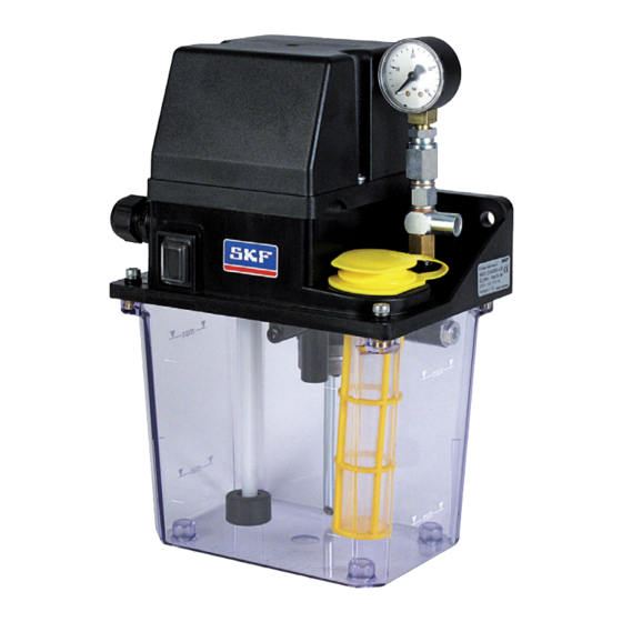
- Page 1 MSU Gear Pump Unit Assembly instructions acc. to EC Dir. 2006/42/EC for partly completed machinery with associated operating instructions for industrial machinery for use in single-line centralized oil lubrication systems Version 03...
- Page 2 Page 2 Notes Service Masthead ©SKF Lubrication Systems Germany GmbH If you have technical questions, please contact These assembly instructions with associated op- This documentation is protected by copyright. the following addresses: erating instructions according to EC Machinery SKF Lubrication Systems Germany GmbH...
-
Page 3: Table Of Contents
Page 3 Table of contents Assembly instructions table of contents Design and function Information concerning EC Declaration of Confor- Assembly of the MSU gear pump General information mity and EC Declaration of Incorporation 4.3.1 Mounting diagram Design Explanation of symbols and signs 4.3.2 Dimensions of the MSU gear pump unit 19 Functional description Electrical connection... -
Page 4: Information Concerning Ec Declaration Of Conformity And Ec Declaration Of Incorporation
The aforementioned product may, with ref- not bear a CE marking in respect of Directive erence to EC Directive 97/23/EC concern- 97/23/EC.SKF Lubrication Systems Germany (c) The commissioning of the products here ing pressure equipment, only be used in GmbH classifies them according to Article 3,... -
Page 5: Explanation Of Symbols And Signs
Explanation of symbols Page 5 Explanation of symbols and signs You will find these symbols, which warn of Instructions placed directly on the machines/ specific dangers to persons, material assets, or grease lubrication pump units, such as: the environment, next to all safety instructions You are responsible! in these operating instructions. -
Page 6: Safety Instructions
Intended use tion, vapors, or such fluids whose vapor pres- The gear pump units of the SKF MSU series sure exceeds normal atmospheric pressure are designed for the supply of centralized lub- (1013 mbar) by more than 0.5 bar at their rication systems in plants and machines. -
Page 7: Authorized Personnel
Assembly instructions Page 7 Electric shock hazard Authorized personnel System pressure hazard Only qualified technical personnel may install, Electrical connections for the described prod- operate, maintain, and repair the products de- uct may only be established by qualified and Lubrication systems are pressurized trained personnel authorized to do so by the scribed in the assembly instructions. -
Page 8: Existing Residual Risks (Residual Risk Assessment)
Page 8 Existing residual risks (residual risk assessment) Residual risk Remedy Life cycle: Assembly During installation of the lubrication line - • Apply an open-end wrench (size 14 mm) to the pump outlet port and counter the following turn- The pump outlet port has broken off from the ing torque pump housing due to inadequate counterforce at the pump outlet port. - Page 9 Page 9 Residual risk Remedy Fire hazard when working with an open cap • Turn off pump unit and allow motor to cool down prior to performing work Life cycle: Malfunctions, fault-finding Strong heating of the motor due to a motor jam •...
-
Page 10: Lubricants
Directive 67/548/EEC, Article 2, Para. 2, may properties of the lubricants are critically im- ing/friction point, their expected load during only be filled into SKF centralized lubrication portant in making these selections. operation, and the anticipated ambient condi- systems and components and delivered and/or tions must be taken into account. -
Page 11: Approved Lubricants
You can request an overview of the lubricant tem. It is recommended that an indica- tests offered by SKF Lubrication Systems tion of the lubricant in use be attached Germany GmbH from the company's Service to the lubricant reservoir in order to department. -
Page 12: Lubricants And The Environment
Page 12 Assembly instructions Lubricants and the environment Lubricant hazards Warning! Danger! Follow the safety instructions on the Lubricants can contaminate soil and Centralized lubrication systems must al- lubricant's safety data sheet. bodies of water. Lubricants must be ways be free of leaks. Leaking lubricant properly used and disposed of. -
Page 13: Overview
Assembly instructions Page 13 3. Overview Unit components Unit components Item Description Chapter Fastening holes 4.3/4.31 Pressure-regulating valve Lubricant reservoir OI Chap. 5.3 Filler socket with strainer Float switch (fill level switch) 4.4.3 Pushbutton (DK) OI Chap. 6.1 Cable fitting 4.3.2 230 VAC Electrical connection... -
Page 14: Product Code
Assembly instructions 3.1.1 Order examples MSU1-11AA10010+428 Table of product codes MSU series compact unit for an oil delivery rate MSU x-x x x x x x x x 0 +xxx of 0.1 l/min. (1), operating pressure 13 bar (1), Compact unit... -
Page 15: Assembly
Assembly instructions Page 15 4. Assembly General information Setup and attachment Only qualified technical personnel may install, The pump unit should be installed in a place During assembly and especially when drilling, operate, maintain, and repair the MSU gear protected from contamination, water splashes, always pay attention to the following: and vibrations. -
Page 16: Mounting Equipment
Warning! gon socket screws) depends on the cus- When drilling the assembly holes, you tomer’s installation. SKF recommends a must be careful of any supply lines or torque between 12 and 15 Nm. other units, as well as of other haz- ards such as moving parts. -
Page 17: Assembly Of The Msu Gear Pump
The torque of the fixing screws is de- To prevent the pump outlet port from termined by the customer. SKF recom- possibly breaking off from the pump mends a torque between 12 and 15 Nm. housing in the following assembly proce-... -
Page 18: Mounting Diagram
Page 18 Assembly instructions 4.3.1 Mounting diagram Mounting diagram, Fig. 1 Cover cap Pump outlet port, M10x1 (with recessed head Connection for lubricant line (Pozidriv PZ2) screws) (178) 2x Ø 8.8 21.6 Assembly holes Venting slot Connection cable provided by customer Minimum mounting dimensions A = width:... -
Page 19: Dimensions Of The Msu Gear Pump Unit
Assembly instructions Page 19 4.3.2 Dimensions of the MSU gear pump unit Dimensions of the MSU gear pump unit, Fig. 2 Cover cap for connection cable Ø 6 mm up to Ø 12 mm Pump outlet M10x1 21.6 Connection for lubricant line 32.5 View A... -
Page 20: Electrical Connection
Page 20 Assembly instructions Electrical connection 4.4.1 General information The MSU gear pump unit is driven by a 230 V Danger! Danger! 50/60 Hz single-phase AC motor or optionally Electrical connections for the product The available mains voltage (supply by a 24 VDC DC motor. may only be established by qualified and voltage) must be in accordance with In both designs, the cables are introduced... -
Page 21: Electric Motor And Sensor Connections
Draw the connection cable provided by customer into the cable fitting. Connect the cable according to the wiring diagram (Fig. 3 to Fig. 8), the wiring dia- gram in the cover cap, or the SKF customer drawing. Tighten the cable fitting. -
Page 22: Electrical Characteristics, 230 Vac Design
Page 22 Assembly instructions 4.4.3 Electrical characteristics, 230 VAC design Electrical characteristics of the 230 VAC design Protection class per EN 60529 IP 54 Motor Operating voltage 230 VAC Frequency 50 Hz 60 Hz Rated speed 2800 rpm 3300 rpm Rated current ±15% 0.895 A 0.672 A... - Page 23 Assembly instructions Page 23 Terminal strip , Fig. 5 Wiring diagram without pushbutton, Fig. 3 Wiring diagram with pushbutton, Fig. 4 Cable fitting M20x1.5, cable harness output MSU1-1xxxxxx0x+428/429/434/410/436 MSU1-1xxxxxx1x+428/429/434/410/436 Clamping range 6 to 12 mm MSU1-2xxxxxx0x+428/429/434/410/436 MSU1-2xxxxxx1x+428/429/434/410/436 Flat tab receptacle 230V/115V/100V/220V/200V 6.3x0.8 (ground) 230V/115V/100V/220V/200V...
-
Page 24: Electrical Characteristics, 24 Vdc Design
Page 24 Assembly instructions 4.4.4 Electrical characteristics, 24 VDC design Electrical characteristics, 24 VDC design Protection class per EN 60529 IP 54 Motor Operating voltage 24 VDC Rated speed 3600 rpm Rated current 2.3 A Starting current 13.5 A Rated output 55 W Duty cycle per DIN EN 60034-1 * S3, 10% ON-time, 10-min. - Page 25 Assembly instructions Page 25 Terminal strip , Fig. 8 Wiring diagram without pushbutton, Fig. 6 Wiring diagram with pushbutton, Fig. 7 MSU1-1xxxxxx0x+924 MSU1-1xxxxxx1x+924 Cable fitting M20x1.5, cable harness output MSU1-2xxxxxx0x+924 MSU1-2xxxxxx1x+924 24V DC PELV 24V DC PELV Legend to Figures 6 and 7 = Pump motor WS = Float switch, contacts shown for full reservoir...
-
Page 26: Lubrication Line Arrangement
Page 26 Assembly instructions Lubrication line arrangement The pipes, hoses, shutoff valves, directional transitions. Sudden changes of direction harm to persons or damage to other material should be avoided if possible. assets. control valves, fittings, etc. that will be used must be designed for the maximum operating pressure of the lubrication unit, the permis- Note! -
Page 27: Venting The Centralized Lubrication System
Single-line distributor Remove the lubricant line at the inlet to the first distributor (2) Type designation SKF Lubrication Systems Germany GmbH Power supply MSU.-...-..+428 Allow the pump to run until lubricant with- 230V 50/60Hz IEC38 out bubbles discharges. - Page 29 Page 29 MSU Gear Pump Unit Operating instructions associated with assembly instructions...
-
Page 30: Operating Instructions
Caused by the installation of non-original tions to these operating instructions. The safety instructions listed in Chapter 1, SKF components or SKF spare parts "Safety instructions," of the assembly instruc- Caused by inappropriate usage tions also apply without restrictions to these Resulting from improper assembly, configu- operating instructions. -
Page 31: Transport, Delivery, And Storage
Page 31 3. Transport, delivery, and storage General information Lubrication units General notes SKF Lubrication Systems Germany GmbH Ambient conditions: dry and dust-free The product(s) can be enveloped in plastic products are packaged in accordance with surroundings, storage in well ventilated film to provide low-dust storage. -
Page 32: Assembly
Page 32 4. Assembly/5. Design and function 4. Assembly 5. Design and function Information on assembly General information The assembly procedure for the MSU gear The MSU is a reservoir unit with an electrically The pressure-regulating valve is required in pump unit is described in detail in the assem- driven gear pump that contains all hydraulic order to limit the maximum permissible sys-... -
Page 33: Functional Description
5. Design and function Page 33 Functional description The MSU gear pump unit is designed to supply The lubricating frequency, ON-time, and inter- Single-line centralized lubrication system, Fig. 1 intermittently operated single-line centralized val time are set by the customer. An interim lubrication can be triggered manu- oil lubrication systems. -
Page 34: Control Elements
Page 34 6. Control elements/7. Commissioning 6. Control elements 7. Commissioning Pushbutton DK General information The MSU gear pump unit can optionally be The described product functions automatically. Observe the instructions from the equipped with a pushbutton for manually trig- The lubricant transport in the lubrication lines machine manufacturer regarding the gering an interim lubrication. -
Page 35: Commissioning Procedure
Chapter 4.6, "Venting the cen- clean lubricant. The product is then operated tralized lubrication system." The product can also be returned to SKF until lubricant without bubbles is discharged at Lubrication Systems Germany GmbH for dis- all lubrication points. -
Page 36: Maintenance And Service
Service department of switched off before opening any of the lukewarm: SKF Lubrication Systems Germany GmbH for product's components. SKF Lubrication Systems Germany GmbH assistance. products are low-maintenance. However, all... -
Page 37: General Information
General information The following maintenance and repair work The maintenance intervals depend on customer- SKF Lubrication Systems Germany GmbH shall must be performed on a regular basis: specific settings and operating conditions. The not be held liable for damages resulting from... -
Page 38: Replacing A Defective Fuse (24 Vdc)
Page 38 9. Maintenance and service Replacing a defective fuse (24 VDC) Note! Push the bayonet closure (1) of the fuse Fuse replacement, Fig. 3 The cause of the malfunction must be housing into the fuse box and turn it clock resolved prior to replacing the defective wise to seal fuse. -
Page 39: Operational And Pump Faults
Service department of reservoir screws. SKF Lubrication Systems Germany GmbH. Secure the lubricant reservoir against fall- ing. Venting the pump unit , Fig. 4 Loosen the lubricant reservoir by gently... - Page 40 Page 40 10. Operational and pump faults Unit and system malfunctions Fault Possible cause Rectification No operating voltage on motor Unit motor fails • Check mains connection, check mains plug and/or cable; connect properly if necessary. to start when the •...
-
Page 41: Technical Data
11. Technical data Page 41 11. Technical data 11.1 Electrical characteristics The electrical characteristics for the pump mo- MSU characteristics tor, pressure switch, and float switch are given Pump unit in Chapter 4.4.3, "Electrical characteristics," of 230 VAC/50 Hz 230 VAC/60 Hz 24 VDC the assembly instructions. -
Page 42: Accessories
Page 42 12. Accessories 12. Accessories Accessories Pressure gauge, complete, Fig. 5 Fig. Description Order No. Pressure gauge 0 to 25 bar, complete 169-102-506.U1 Pressure gauge 0 to 40 bar, complete 169-104-008.U1 Fuse 179-990-206 Cartridge fuse link (5x20 mm) T2A per DIN EN 60127-2 (VDE 0820-2) standard sheet 3... - Page 43 Page 43...
- Page 44 All SKF products may be used only for their intended purpose as described in these assembly instructions with associated operating instructions. If assembly/operating instructions are supplied together with the products, they must be read and followed.
Need help?
Do you have a question about the MSU Series and is the answer not in the manual?
Questions and answers